Available languages
Available languages
Quick Links
Dell™ PowerConnect™
6200 Series Stackable Switches
Getting Started Guide
使用入门指南
Příručka Začínáme
Guide de mise en route
Erste Schritte
Οδηγός για γρήγορο ξεκίνηµα
はじめに
시작 설명서
Instrukcja uruchomienia
Guía de introducción
Başlangıç Kılavuzu
Models PC6224, PC6248, PC6224P, PC6248P, and PC6224F
w w w . d e l l . c o m | s u p p o r t . d e l l . c o m
Chapters

Related Manuals for Dell 6224 - PowerConnect Switch - Stackable


Summary of Contents for Dell 6224 - PowerConnect Switch - Stackable
-
Page 1: Getting Started Guide
Dell™ PowerConnect™ 6200 Series Stackable Switches Getting Started Guide 使用入门指南 Příručka Začínáme Guide de mise en route Erste Schritte Οδηγός για γρήγορο ξεκίνηµα はじめに 시작 설명서 Instrukcja uruchomienia Guía de introducción Başlangıç Kılavuzu Models PC6224, PC6248, PC6224P, PC6248P, and PC6224F... - Page 3 Dell™ PowerConnect™ 6200 Series Stackable Switches Getting Started Guide Models PC6224, PC6248, PC6224P, PC6248P, and PC6224F w w w . d e l l . c o m | s u p p o r t . d e l l . c o m...
- Page 4 Reproduction in any manner whatsoever without the written permission of Dell Inc. is strictly forbidden. Trademarks used in this text: Dell, the DELL logo, and PowerConnect are trademarks of Dell Inc.; Microsoft and Windows are registered trademarks of Microsoft Corporation.
-
Page 5: Table Of Contents
Contents Installation Site Preparation ......Unpacking the Switch ......Package Contents . - Page 6 Managing a Stack Master and Member Switches ..... . . Stack Startup ....... Topology Discovery .
-
Page 7: Site Preparation
This document provides basic information to install, configure, and operate Dell™ PowerConnect™ PC6224, PC6248, PC6224P, PC6248P, and PC6224F systems. For more information, see the User's Guide, which is available on your User Documentation CD, or check the Dell Support web site at support.dell.com for the latest updates on documentation and firmware. -
Page 8: Unpacking Steps
Unpacking Steps NOTE: Before unpacking the switch, inspect the container and immediately report any evidence of damage. Place the container on a clean, flat surface and cut all straps securing the container. Open the container or remove the container top. Carefully remove the switch from the container and place it on a secure and clean surface. -
Page 9: Installing As A Free-Standing Switch
Insert the switch into the 48.26 cm (19 inch) rack, ensuring that the rack-mounting holes on the switch line up to the mounting holes in the rack. Secure the switch to the rack with either the rack bolts or cage nuts and cage nut bolts with washers (depending on the kind of rack you have). -
Page 10: Assembling A Stack
Figure 1-2. Connecting Power Cable Assembling a Stack You can stack PowerConnect 6200 series switches up to 12 switches high, supporting up to 576 front panel ports. Create a stack by connecting adjacent units using the stacking ports on the left side of the switch rear. See Figure 1-3. - Page 11 Figure 1-3. Connecting a Stack of Switches NOTE: Long cable not shown in Figure 1-3. The resulting ring topology allows the entire stack to function as a single switch with resilient fail-over capabilities. Getting Started Guide...
-
Page 12: Connecting The Terminal To The Switch
Read the release notes for this product before proceeding. You can download the release notes from the Dell Support website at support.dell.com. NOTE: We recommend that you obtain the most recent version of the user documentation from the Dell Support website at support.dell.com. Connecting the Terminal to the Switch To monitor and configure the switch via serial console, use the console port on the rear of the switch to connect it to a terminal desktop system running terminal emulation software. -
Page 13: Booting The Switch
Connect the female connector of the RS-232 crossover cable directly to the switch console port, and tighten the captive retaining bolts. The PowerConnect 6200 series console ports are located on the rear panel as shown in Figure 1-4. NOTE: If you are installing a stack of switches, connect the terminal to the Master Switch. This switch will light the Master Switch LED, the top left LED in the array on the front panel. -
Page 14: Initial Configuration
The IP address of the management VLAN default gateway for configuring the default route. Initial Configuration Procedure You can perform the initial configuration using the Dell Easy Setup Wizard, or by using the Command Line Interface (CLI). The Setup Wizard automatically starts when the switch configuration file is empty. You can exit the wizard at any point by entering [ctrl+z], but all configuration settings specified will be discarded (the switch will use the default values). -
Page 15: Example Session
{ }. If you presswith no options defined, the default value is accepted. Help text is in parentheses. The following example contains the sequence of prompts and responses associated with running an example Dell Easy Setup Wizard session, using the input values listed above. After the switch completes the POST and is booted, the following dialog appears:... - Page 16 Step 1: The system is not configured for SNMP management by default. To manage the switch using SNMP (required for Dell Open Manage Network Manager) you can: o Set up the initial SNMP version 1 & 2 now. o Return later and set up other SNMP accounts. (For more information on setting up an SNMP version 3 account, see the user documentation).
-
Page 17
If the information is incorrect, select (N) to discard configuration and restart the wizard: [Y/N] y
Thank you for using the Dell Easy Setup Wizard. You will now enter CLI mode. Getting Started Guide... -
Page 18: Master And Member Switches
Managing a Stack Master and Member Switches A stack of switches can be managed as a single entity when connected together. The stack can be managed from a web-based interface, an SNMP management station, or a CLI. When a stack is created, one switch automatically becomes the master switch. -
Page 19: System Initialization
System Initialization If the Master Switch determines during the firmware version consistency check that all switches are running the same version of firmware, the switch will be initialized for Stacking Mode. System Initialization for Normal Stacking Mode The Master Switch will initialize the stack using the last saved system configuration file. For those switches that do not have a configuration file, the system will apply default settings to those switches. -
Page 20: User Controls
User Controls Use the following CLI commands to control this feature. See the CLI Reference Guide for details on the syntax of each command. movemanagement reload member set description switch priority switch renumber stacking show stack-port show stack-port counters show stack-port diag show switch show supported switchtype Getting Started Guide... -
Page 21: Front Panels
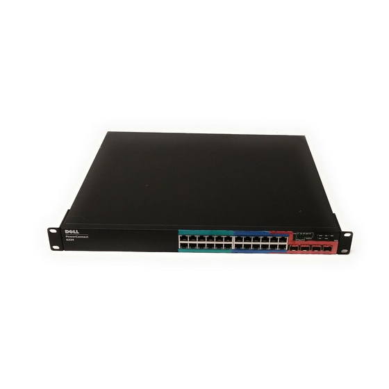
Front Panels and LEDs This appendix describes the front panels and LEDs of the Dell PowerConnect PC6224, PC6248, PC6224P, PC6248P, and PC6224F systems. Front Panels The front panels of the PowerConnect 6200 series systems are shown in the figures below. -
Page 22: Systems Leds
Figure 1-4. PC 6248P Figure 1-5. PC 6224F LEDs The following sections list the LEDs. Systems LEDs Table 1-1. System LEDs State Fan Status • Green: All Fans are operating correctly • Red: One or more fans have failed Power Supply Status •... -
Page 23: Rj-45 Leds (Poe)
RJ-45 LEDs (PoE) The RJ-45 ports will have two integrated LEDs (One bi-color and one single color). Table 1-2. RJ-45 LEDs (PoE) State Left - Single color: Port link/activity • Green: Link at 10/100/1000 Mbps • Solid: Link but no activity •... - Page 24 Getting Started Guide...
- Page 25 Dell™ PowerConnect™ 6200 系列可堆叠交换机 使用入门指南 型号: PC6224, PC6248, PC6224P, PC6248P 和 PC6224F w w w . d e l l . c o m | s u p p o r t . d e l l . c o m...
- Page 26 注、注意和警告 注: 注意: 警告: 警告表示可能会导致财产损失、人身伤害甚至死亡。 ____________________ © 2007 Dell Inc. Dell Inc. Dell Inc. Microsoft Corporation Dell DELL PowerConnect Microsoft Windows Dell Inc. 型号: PC6224, PC6248, PC6224P, PC6248P 和 PC6224F 2007 年 9 月 修订版 A02 P/N YC897...
- Page 27 安装 ............. . .
- Page 28 管理堆叠 ............
- Page 29 Dell™ PowerConnect™ PC6224, PC6248, PC6224P , User Documentation CD PC6248P PC6224F Dell support.dell.com PowerConnect 6200 48.26 • — 100-250 VAC 50-60 Hz • — • — • — 45C 32 113F 包装箱物品 • PowerConnect • • RS-232 • • User Documentation CD •...
- Page 30 打开包装步骤 注: 警告: PowerConnect RPS-600 PowerConnect EPS-470 在机架中安装 警告: 警告: 警告: 1-1. 48.26...
- Page 31 注意: 警告: 安装为自立式交换机 注意: RS-232 VT100 VT100 RS-232 DB-9 注: 警告: PowerConnect RPS-600 PowerConnect EPS-470 12 VDC 注:...
- Page 32 1-2. PowerConnect 6200 注:...
- Page 33 1-3. 注:...
- Page 34 User Documentation CD 注: Dell support.dell.com 注: Dell support.dell.com DB-9 (DTE) • VT100 VT100 • RS-232 DB-9 注: RS-232 VT100 9600 none VT100 Ctrl ® ® Microsoft Windows 注意: 在 Microsoft Windows 2000 中使用超级终端时,请确保已安装 Windows 2000 Service Pack 2 或更高版本。使用 Windows 2000 Service Pack 2 可以确保箭头键在超级终端的 VT100 仿真中正常...
- Page 35 1-4. RS-232 VT100 VT100 (POST) POST POST POST POST...
- Page 36 注: • PowerConnect • PowerConnect • Dell VT100 注: 注: HTTP Web • VLAN VLAN • • VLAN 初始配置过程 Dell (CLI) [ctrl+z] • • HTTP • VLAN • SNMP SNMP SNMP • •...
-
Page 37
注:
Dell POST Welcome to Dell Easy Setup Wizard Dell The setup wizard guides you through the initial switch configuration, and gets you up and running as quickly as possible. You can skip the setup wizard, and enter CLI mode to manually configure the switch. - Page 38 The wizard automatically assigns the highest access level [Privilege Level 15] to this account. You can use Dell Open Manage Network Manager or other management interfaces to change this setting and to add additional management systems later.
- Page 39 Now we need to configure your initial privilege (Level 15) user account. This account is used to login to the CLI and Web interface. You may set up other accounts and change privilege levels later. For more information on setting up user accounts and changing privilege levels, see the User’s Guide.
-
Page 40
If the information is incorrect, select (N) to discard configuration and restart the wizard: [Y/N]
Thank you for using the Dell Easy Setup Wizard. You will now enter CLI mode. Dell... - Page 41 SNMP DHCP • • • • 拓扑搜索 注: 参 CLI 参考手册 《 》 自动堆叠 ID 分配 使用 CLI 或 Web 界面可查看堆栈 ID 。 FLASH 检查固件版本 系统初始化...
-
Page 42: Cli Web
系统初始化为正常堆叠模式 系统初始化为暂挂堆叠模式 CLI / WEB / SNMP 插入和卸下交换机 作为独立交换机运行 堆叠 ID 重新编号... - Page 43 movemanagement reload member set description switch priority switch renumber stacking show stack-port show stack-port counters show stack-port diag show switch show supported switchtype...
- Page 45 Dell PowerConnect PC6224 PC6248 PC6224P PC6248P PC6224F PowerConnect 6200 图 1-1. PC 6224 图 1-2. PC 6248 图 1-3. PC 6224P...
-
Page 46: Led
图 1-4. PC 6248P 图 1-5. PC 6224F 系统 LED 表 1-1. 系统 LED 状态 风扇状态 • • 电源设备状态 • • 冗余电源设备 • • • 诊断程序 • • • 温度 • •... -
Page 47: Led (Poe)
RJ-45 LED (PoE) RJ-45 表 1-2. RJ-45 LED (PoE) 状态 左 - 单色:端口链路 / 活动 • 10/100/1000 Mbps • • • 右 ( POE 模式) - 双色: • (PD) • • • XFP LED 表 1-3. XFP LED 状态 单色: •... - Page 49 Dell™ PowerConnect™ Stohovatelné přepínače řady 6200 Příručka Začínáme Modely PC6224, PC6248, PC6224P, PC6248P a PC6224F w w w . d e l l . c o m | s u p p o r t . d e l l . c o m...
- Page 50 V tomto dokumentu mohou být použity další ochranné známky a obchodní názvy odkazující na subjekty, kterým tyto známky či názvy patří, nebo na jejich výrobky. Společnost Dell Inc. se zříká jakýchkoli vlastnických zájmů o jiné než vlastní ochranné známky a obchodní názvy.
- Page 51 Obsah 1 Instalace ......Příprava místa Rozbalení přepínače ......Obsah balení...
-
Page 52: Obsah
3 Správa stohu Přepínač Master a členské přepínače ....Spuštění stohu ...... -
Page 53: Instalace
Instalace V tomto dokumentu jsou shrnuty základní informace k instalaci, konfiguraci a provozu systémů Dell™ PowerConnect™ PC6224, PC6248, PC6224P, PC6248P a PC6224F. Další informace viz Příručka uživatele, která je k dispozici na disku CD User Documentation s dokumentací pro uživatele, nebo navštivte webovou stránku technické... -
Page 54: Postup Rozbalení
Postup rozbalení POZNÁMKA: Před vlastním rozbalením přepínače zkontrolujte krabici a ihned oznamte všechna případná poškození. 1 Krabici umístěte na čistý a plochý povrch a přestřihněte všechny pásky, které ji zabezpečují. 2 Otevřete krabici nebo sejměte její vrchní díl. 3 Opatrně vyjměte přepínač z krabice a položte ho na pevný a čistý povrch. 4 Odstraňte veškerý... -
Page 55: Instalace Volně Instalovaného Přepínače
2 Vložte dodané šrouby do montážních otvorů a utáhněte je šroubovákem. 3 Postup zopakujte u konzoly na opačné straně přepínače. 4 Zasuňte přepínač do stojanu 48,26 cm (19 palců) tak, aby montážní otvory na přepínači lícovaly s montážními otvory ve stojanu. 5 Připevněte přepínač... -
Page 56: Připojení Přepínače K Napájecímu Zdroji
Připojení přepínače k napájecímu zdroji POZOR: Přečtěte si bezpečnostní informace obsažené v Informační příručce produktu a také bezpečnostní informace k ostatním přepínačům, které jsou k přepínači připojené nebo na kterých je přepínač umístěný. 1 Připojte dodaný napájecí kabel do napájecího konektoru střídavého napětí, který je umístěn na zadním panelu. -
Page 57: Stohování
Stohování Přepínače PowerConnect 6200 series můžete integrovat do jednoho stohu až do výšky 12 přepínačů s celkovou podporou až 576 portů na čelních panelech. Vytvořte stoh propojením přilehlých jednotek s použitím stohovacích portů na levé straně zadní části přepínače. Viz Obr. 1-3. POZNÁMKA: Přepínače musí... -
Page 58: Spuštění A Konfigurace Přepínače
CD s dokumentací pro uživatele. POZNÁMKA: Před zahájením prací si přečtěte poznámky k verzi tohoto výrobku. Tyto poznámky lze stáhnout z webové stránky technické podpory společnosti Dell na adrese support.dell.com. POZNÁMKA: Doporučujeme stáhnout nejnovější verzi uživatelské dokumentace z webové... - Page 59 UPOZORNĚNÍ: Používáte-li program Hyperterminál v systému Microsoft Windows 2000, zkontrolujte, že máte nainstalovanou aktualizaci Windows 2000 Service Pack 2 nebo vyšší. V systému Windows 2000 s aktualizací Service Pack 2 pracují šipkové klávesy v rámci emulace VT100 Hyperterminálu správně. Další informace o aktualizacích Service Pack systému Windows 2000 najdete na adrese www.microsoft.com.
-
Page 60: Bootování Přepínače
• Bylo navázáno spojení s konzolou a na obrazovce terminálu VT100 nebo jeho ekvivalentu se zobrazil průvodce konfigurací Dell Easy Setup Wizard. Počáteční konfigurace přepínače probíhá prostřednictvím portu konzoly. Po dokončení počáteční konfigurace můžete přepínač spravovat buď z již připojeného portu konzoly, nebo vzdáleně... -
Page 61: Postup Počáteční Konfigurace
Postup počáteční konfigurace Počáteční konfiguraci můžete provést pomocí průvodce konfigurací Dell Easy Setup Wizard nebo můžete použít rozhraní příkazového řádku. Průvodce konfigurací se spustí automaticky, jestliže je konfigurační soubor přepínače prázdný. Průvodce konfigurací můžete kdykoli ukončit stisknutím kláves [ctrl+z], všechna provedená nastavení se však stornují (přepínač bude pracovat s výchozími hodnotami). - Page 62 Text nápovědy je uveden v kulatých závorkách. Následující příklad znázorňuje posloupnost dotazů a reakcí tak, jak se zobrazují v průběhu ukázkové relace průvodce konfigurací Dell Easy Setup Wizard s použitím výše uvedených vstupních hodnot. Po dokončení testu POST a plném spuštění přepínače se zobrazí následující dialog:...
- Page 63 The wizard automatically assigns the highest access level [Privilege Level 15] to this account. You can use Dell Open Manage Network Manager or other management interfaces to change this setting and to add additional management systems later.
-
Page 64
If the information is incorrect, select (N) to discard configuration and restart the wizard: [Y/N] y
Thank you for using the Dell Easy Setup Wizard. You will now enter CLI mode. Příručka Začínáme... -
Page 65: Správa Stohu
Správa stohu Přepínač Master a členské přepínače Jestliže jsou přepínače vzájemně propojené, je možné spravovat celý stoh jako jeden celek. Stoh může být spravován prostřednictvím webového rozhraní, ze stanice správy SNMP nebo prostřednictvím rozhraní příkazového řádku. Po vytvoření stohu se jeden z přepínačů automaticky stává přepínačem Master. -
Page 66: Kontrola Verze Firmwaru
Kontrola verze firmwaru Po přidělení Stack ID provede přepínač Master kontrolu konzistence. Tímto krokem je zjištěno, zda je ve všech přepínačích stohu spuštěna stejná verze firmwaru. Jestliže se neshodují verze softwaru přepínačů, nebudou porty členského přepínače identifikovány jako platné pro provoz. Tento stav je označován jako pozastavený stohovací režim (Suspended Stacking Mode). -
Page 67: Rozhraní Příkazového Řádku, Telnet A Webové Rozhraní
Rozhraní příkazového řádku, Telnet a webové rozhraní K synchronizaci firmwaru členského přepínače s firmwarem uloženým v přepínači Master můžete použít rozhraní příkazového řádku, webové rozhraní nebo rozhraní SNMP. Vložení a odebrání přepínačů Přepínače můžete vkládat do aktuálního stohu a odebírat z aktuálního stohu bez vypnutí elektrického napájení. - Page 68 Příručka Začínáme...
-
Page 69: Čelní Panely A Indikátory Led
Čelní panely a indikátory LED Tato příloha popisuje čelní panely a indikátory LED systémů Dell PowerConnect PC6224, PC6248, PC6224P, PC6248P a PC6224F. Čelní panely Na níže uvedených obrázcích jsou znázorněny čelní panely systémů PowerConnect 6200 series. Obr. 1-1. PC 6224 Obr. -
Page 70: Indikátory Led
Obr. 1-4. PC 6248P Obr. 1-5. PC 6224F Indikátory LED V následující části jsou uvedeny indikátory LED. Indikátory LED systémů Table 1-1. Indikátory LED systémù Indikátor LED Stav • Zelená: Všechny ventilátory fungují normálně. Stav ventilátorů • Červená: Jeden nebo více ventilátorů selhalo. •... -
Page 71: Indikátory Led Rj-45 (Poe)
Indikátory LED RJ-45 (PoE) Porty RJ-45 obsahují dva integrované indikátory LED (jeden dvoubarevný a jeden jednobarevný). Table 1-2. Indikátory LED RJ-45 (PoE) Indikátor LED Stav • Zelená: Spojení rychlostí 10/100/1000 Mb/s Levý - jednobarevný: Port - spojení/činnost • Trvale svítí: Připojení, avšak žádná činnost. •... - Page 72 Příručka Začínáme...
- Page 73 Commutateurs empilables Dell™ PowerConnect™ - Série 6200 Guide de mise en route Modèles PC6224, PC6248, PC6224P, PC6248P et PC6224F w w w . d e l l . c o m | s u p p o r t . d e l l . c o m...
- Page 74 Tous les autres noms de marques et marques commerciales utilisés dans ce document se rapportent aux sociétés propriétaires des marques et des noms de ces produits. Dell Inc. décline tout intérêt dans l'utilisation des marques déposées et des noms de marques ne lui appartenant pas.
- Page 75 Sommaire Installation Préparation du site ......Déballage du commutateur ......Contenu du carton .
- Page 76 Gestion d'une pile Commutateur maître et commutateurs membres ....Démarrage de la pile ......Détection de la topologie .
-
Page 77: Préparation Du Site
Pour obtenir des informations plus détaillées, reportez-vous au document User's Guide (Guide d'utilisation), que vous trouverez sur le CD de documentation. Vous pouvez également vous rendre sur le site support.dell.com pour prendre connaissance des dernières mises à jour concernant la documentation et le micrologiciel. -
Page 78: Montage Du Commutateur
Déballage REMARQUE : avant de déballer le commutateur, examinez le carton d'emballage et signalez immédiatement tout dommage apparent. Posez le conteneur sur une surface plane et propre et coupez toutes les sangles d'attache. Ouvrez le carton ou retirez le couvercle. Retirez avec précaution le commutateur de son carton et posez-le sur une surface propre et stable. -
Page 79: Installation D'un Commutateur Autonome
Insérez les boulons qui vous ont été fournis dans les orifices de montage, puis serrez-les à l'aide d'un tournevis. Répétez l'opération de l'autre côté du commutateur. Insérez le commutateur dans le rack de 19 pouces (48,26 cm), en veillant à ce que ses orifices de montage soient bien alignés sur ceux du rack. -
Page 80: Connexion Du Commutateur À Un Bloc D'alimentation
Connexion du commutateur à un bloc d'alimentation PRÉCAUTION : prenez connaissance des consignes de sécurité figurant dans le document Product Information Guide (Guide d'informations sur le produit), ainsi que des informations similaires concernant les autres appareils connectés au commutateur. Branchez le câble d'alimentation en CA qui vous a été fourni sur le connecteur approprié du panneau arrière. -
Page 81: Assemblage D'une Pile
Assemblage d'une pile Une pile peut comprendre 12 commutateurs PowerConnect 6200, soit un total de 576 ports frontaux. Pour créer une pile, connectez les commutateurs adjacents en utilisant les ports situés à l'arrière de chaque commutateur, du côté gauche. Voir la figure 1-3. REMARQUE : Les commutateurs doivent être éteints lorsque vous les ajoutez à... -
Page 82: Connexion Du Terminal Au Commutateur
REMARQUE : avant de continuer, lisez les notes d'édition concernant ce produit. Vous pouvez les télécharger à partir du site d'assistance technique de Dell, support.dell.com. REMARQUE : nous vous recommandons de vous procurer la version la plus récente de la documen- tation, disponible sur le site support.dell.com. -
Page 83: Démarrage Du Commutateur
AVIS : si vous utilisez HyperTerminal sous Microsoft Windows 2000, assurez-vous que le Service Pack 2 (ou suivant) du système d'exploitation est installé. Ce service pack permet aux touches fléchées de fonctionner correctement dans l'émulation VT100 d'HyperTerminal. Pour plus d'informations concernant les services pack Windows 2000, visitez le site www.microsoft.com. -
Page 84: Configuration Initiale
Le commutateur PowerConnect a démarré correctement. • La connexion à la console est établie et l'invite de l'assistant Dell Easy Setup est affichée sur l'écran d'un terminal VT100 ou équivalent. La configuration initiale du commutateur est effectuée via le port de console. Une fois cette première étape effectuée, le commutateur peut être géré... - Page 85 Ce dernier effectue les opérations suivantes : • Il met en place le compte utilisateur privilégié initial et le mot de passe correspondant. Cette opération est effectuée pendant la configuration. • Il permet l'ouverture de session via l'interface CLI et l'accès HTTP (paramètre d'authentification local uniquement).
- Page 86 L'exemple suivant montre la séquence d'invites et de réponses d'une session exemple de l'assistant Easy Setup de Dell. Les valeurs utilisées sont celles qui sont indiquées ci-dessus. Au démarrage du commutateur (après le POST), la boîte de dialogue suivante s'affiche :...
-
Page 87
To add a management station: Please enter the SNMP community string to be used {Dell_Network_Manager}: Dell_Network_Manager
REMARQUE : s'il est configuré, le niveau d'accès par défaut est défini sur l'accès maximum disponible pour l'interface de gestion SNMP. Initialement, seul SNMPv1/2c est activé. SNMPv3 est désactivé jusqu'à... -
Page 88
If the information is incorrect, select (N) to discard configuration and restart the wizard: [Y/N] y
Thank you for using the Dell Easy Setup Wizard. You will now enter CLI mode. Gestion d'une pile Commutateur maître et commutateurs membres... - Page 89 Démarrage de la pile Détection de la topologie Lorsqu'une pile est créée, un processus de détection de la topologie génère une base de données contenant des informations sur tous les commutateurs de la pile : version du micrologiciel, du matériel, préférences de gestion, adresse MAC et numéro de série. Vous pouvez afficher ces informations à...
- Page 90 Initialisation du système en mode veille Une fois l'initialisation terminée, si des incohérences subsistent entre les versions de micrologiciel utilisées par les unités de la pile, le commutateur maître passe en mode veille (Suspended Stacking Mode). Il est alors le seul à être initialisé avec les informations du fichier de configuration. Les commutateurs membres ne sont pas initialisés et restent en mode passif (tous les ports sont désactivés par défaut).
-
Page 91: Commandes Utilisateur
Commandes utilisateur Les commandes suivantes permettent de gérer le commutateur via l'interface CLI. Reportez-vous au document CLI Reference Guide (Guide de référence CLI) pour plus d'informations sur la syntaxe de chaque commande. movemanagement reload member set description switch priority switch renumber stacking show stack-port show stack-port counters... - Page 92 Guide de mise en route...
-
Page 93: Panneau Avant
Panneau avant et voyants Cette annexe décrit le panneau avant et les voyants des systèmes Dell PowerConnect PC6224, PC6248, PC6224P, PC6248P et PC6224F. Panneau avant Les figures ci-dessous représentent le panneau avant des systèmes PowerConnect de la série 6200. Figure 1-1. PC 6224 Figure 1-2. - Page 94 Figure 1-4. PC 6248P Figure 1-5. PC 6224F Voyants Les sections suivantes répertorient les voyants. Voyants système Tableau 1-1. Voyants système Voyants État État du ventilateur • Vert : tous les ventilateurs fonctionnent correctement. • Rouge : un ventilateur (ou plusieurs) est en panne. État du bloc d'alimentation •...
- Page 95 Voyants des ports RJ-45 (PoE) Les ports RJ-45 comprennent deux voyants intégrés, dont un monochrome et un bicolore. Tableau 1-2. Voyants des ports RJ-45 (PoE) Voyants État Gauche - Monochrome : lien/activité du port. • Vert : lien à 10/100/1000 Mbps. •...
- Page 96 Guide de mise en route...
- Page 97 Dell™ PowerConnect™ 6200-Reihe von stackfähigen Switches Erste Schritte Modelle PC6224, PC6248, PC6224P, PC6248P und PC6224F w w w . d e l l . c o m | s u p p o r t . d e l l . c o m...
- Page 98 Irrtümer und technische Änderungen vorbehalten. © 2007 Dell Inc. Alle Rechte vorbehalten. Die Reproduktion dieses Dokuments in jeglicher Form ohne schriftliche Genehmigung von Dell Inc. ist streng untersagt. Marken in diesem Text: Dell, das DELL Logo und PowerConnect sind Marken von Dell Inc.;...
- Page 99 Inhalt Installation Standortvorbereitung ......Auspacken des Switches ......Inhalt der Verpackung .
- Page 100 Verwalten eines Stacks Master- und untergeordnete Switches ....Stack-Start ....... Topologie-Erkennung .
- Page 101 Installation Dieses Dokument enthält grundlegende Informationen zur Installation, Konfiguration und zum Betrieb von Dell™ PowerConnect™ 6224, PC6248, PC6224P, PC6248P- und PC6224F-Systemen. Weitere Informationen finden Sie im User's Guide (Benutzerhandbuch) auf der CD User Documentation (Benutzerdokumentation). Aktuelle Updates von Dokumentation und Firmware erhalten Sie auf der Dell Support-Website unter support.dell.com.
-
Page 102: Auspacken Des Switches
Auspacken des Switches Inhalt der Verpackung Kontrollieren Sie beim Auspacken der einzelnen Switches, ob jeweils die folgenden Teile vorhanden sind: • Ein PowerConnect-Switch • Ein Netzstromkabel • Ein RS-232-Kabel • Ein Montagekit für die Installation im Rack (zwei Montagehalter, Schrauben und Käfigmuttern) •... -
Page 103: Montage Des Switches
Montage des Switches VORSICHT: Lesen Sie die Sicherheitshinweise im Product Information Guide (Produktinformations- handbuch) sowie die Sicherheitshinweise für andere Switches, die mit dem Switch verbunden werden oder diesen unterstützen. Wechselstrom- und Gleichstromanschluss befinden sich auf der Rückseite des Switches. Es wird empfohlen, ein redundantes Netzteil zu verwenden, z. -
Page 104: Verbinden Eines Switches Mit Einem Terminal
Installation als frei stehende Einheit HINWEIS: Es wird nachdrücklich empfohlen, den Switch in einem Rack zu installieren. Falls kein Rack verwendet wird, installieren Sie den Switch auf einer ebenen Fläche. Die Tragfähig- keit der Fläche muss für den Switch und die zugehörigen Kabel ausreichen. Der Switch wird mit vier selbstklebenden Gummiunterlagen geliefert. - Page 105 Abbildung 1-2. Netzstromkabel anschließen Zusammenfügen eines Stacks PowerConnect-Switches der Serie 6200 lassen sich zu einem Stack mit bis zu 12 Geräten zusammenfügen, wodurch bis zu 576 Ports auf der Vorderseite verfügbar werden. Sie erstellen einen Stack, indem Sie benachbarte Geräte über die Stack-Anschlüsse im linken Bereich der Switch-Rückseiten miteinander verbinden.
- Page 106 Abbildung 1-3. Switch-Stack verbinden ANMERKUNG: Ein langes Kabel ist in Abbildung 1-3 nicht dargestellt. Mit dieser Ring-Topologie lässt sich der gesamte Stack als einzelner Switch mit flexibler Failover- Funktionalität betreiben. Erste Schritte...
-
Page 107: Starten Und Konfigurieren Des Switches
Lesen Sie die Versionshinweise für dieses Produkt, bevor Sie fortfahren. Sie können die Versionshinweise von der Dell Support-Website unter support.dell.com herunterladen. ANMERKUNG: Es wird empfohlen, die aktuelle Version der Benutzerdokumentation von der Dell Support-Website support.dell.com herunterzuladen. Verbinden des Terminals mit dem Switch Um den Switch über die serielle Konsole zu überwachen und zu konfigurieren, verbinden Sie... -
Page 108: Starten Des Switches
HINWEIS: Wenn Sie HyperTerminal mit Microsoft Windows 2000 verwenden, stellen Sie sicher, dass Windows 2000 Service-Pack 2 oder höher installiert ist. Mit Windows 2000 Service-Pack 2 funktionieren die Pfeiltasten in der VT100-Emulierung von HyperTerminal ordnungsgemäß. Weitere Informationen zu den Service-Packs für Windows 2000 finden Sie unter www.microsoft.com. Verbinden Sie den Buchsenstecker des gekreuzten RS-232-Kabels direkt mit dem Switch- Konsolenanschluss und ziehen Sie die Halteschrauben fest. - Page 109 • Der PowerConnect-Switch wurde erfolgreich gestartet. • Es besteht eine Konsolenverbindung, und die Befehlszeile des Dell Easy-Setup-Assistenten wird auf dem Bildschirm des VT100-Terminals bzw. des entsprechenden Systems angezeigt. Die Erstkonfiguration des Switches wird über den Konsolenanschluss vorgenommen. Nach der Erstkonfiguration können Sie den Switch entweder über die bereits bestehende Konsolen- verbindung verwalten oder aus der Ferne über eine Schnittstelle, die bei der Erstkonfiguration...
- Page 110 Durchführen der Erstkonfiguration Sie können die Erstkonfiguration mit dem Dell Easy-Setup-Assistenten vornehmen oder über die Befehlszeilenschnittstelle (CLI) durchführen. Der Setup-Assistent wird automatisch gestartet, wenn die Switch-Konfigurationsdatei leer ist. Sie können den Assistenten jederzeit beenden, indem Sie [Strg+z] eingeben, doch gehen dabei alle festgelegten Konfigurationeinstellungen verloren (der Switch verwendet die Standardwerte).
- Page 111 Standardwert. Hilfetexte sind in Klammern gesetzt. Das folgende Beispiel enthält eine Abfolge von Eingabeaufforderungen und Reaktionen im Rahmen einer beispielhaften Sitzung mit dem Dell Easy-Setup-Assistenten, wobei die oben genannten Eingabewerte verwendet werden. Nachdem der Switch den Einschaltselbsttest durchlaufen und den Startvorgang abgeschlossen hat,...
- Page 112 The wizard automatically assigns the highest access level [Privilege Level 15] to this account. You can use Dell Open Manage Network Manager or other management interfaces to change this setting and to add additional management systems later.
-
Page 113
If the information is incorrect, select (N) to discard configuration and restart the wizard: [Y/N] y
Thank you for using the Dell Easy Setup Wizard. You will now enter CLI mode. Erste Schritte... -
Page 114: Verwalten Eines Stacks
Verwalten eines Stacks Master- und untergeordnete Switches Ein zusammengeschalteter Switch-Stack lässt sich als einzelne Einheit verwalten. Dies kann über eine Web-Oberfläche, eine SNMP-Verwaltungsstation oder eine Befehlszeilenschnittstelle erfolgen. Bei der Bildung eines Stacks wird einer der Switches automatisch zum Master-Switch bestimmt. Sie können dem Master-Switch mit der Konsole manuell eine IP-Adresse zuweisen oder dies mit DHCP automatisch vornehmen lassen. -
Page 115: Firmware-Versionsüberprüfung
Firmware-Versionsüberprüfung Nach der Zuweisung der Stack-IDs führt der Master-Switch eine Konsistenzprüfung durch, um sicherzustellen, dass alle Switches im Stack die gleiche Firmware-Version verwenden. Wenn die Softwareversionen der Switches nicht übereinstimmen, werden die Ports des betreffenden untergeordneten Switches nicht für den Betrieb freigegeben. Dieser Zustand wird als ausgesetzter Stack-Betrieb (Suspended Stacking Mode) bezeichnet. -
Page 116: Betrieb Als Eigenständiger Switch
Betrieb als eigenständiger Switch Wenn ein Switch an einem für Stack-Betrieb aktivierten Port keinen Stack-Partner feststellt, erfolgt der Betrieb als eigenständiger Switch. Wird ein Stack-Partner erkannt, findet für den Switch stets Stack-Betrieb statt. Ändern der Stack-ID Sie können einem Switch manuell eine Stack-ID zuweisen. Ein Switch kann nur eine solche Stack- ID erhalten, die nicht bereits von einem anderen Switch im Stack belegt ist. -
Page 117: Frontblenden Und Leds
Frontblenden und LEDs Dieser Anhang beschreibt die Frontblenden und LEDs der Dell PowerConnect-Systeme PC6224, PC6248, PC6224P, PC6248P und PC6224F. Frontblenden Die nachstehenden Abbildungen zeigen die Frontblenden der Systeme der PowerConnect 6200-Reihe. Abbildung 1-1. PC 6224 Abbildung 1-2. PC 6248 Abbildung 1-3. PC 6224P... -
Page 118: Leds
Abbildung 1-4. PC 6248P Abbildung 1-5. PC 6224F LEDs Im folgenden Abschnitt sind die LEDs aufgeführt. System-LEDs Tabelle 1-1. System-LEDs Status Lüfterstatus • Grün: Alle Lüfter funktionieren korrekt • Rot: Ein oder mehrere Lüfter sind ausgefallen Netzteilstatus • Grün: Netzteil funktioniert ordnungsgemäß •... -
Page 119: Rj-45-Leds (Poe)
RJ-45-LEDs (PoE) Die RJ-45-Anschlüsse sind mit zwei integrierten LEDs (einer zweifarbigen und einer einfarbigen Anzeige) versehen. Tabelle 1-2. RJ-45-LEDs (PoE) Status Verbindungen - Einfarbig: Anschlussverbindung/- • Grün: Verbindung mit 10/100/1000 Mbps aktivität • Stetig: Verbindung ohne Aktivität • Blinkt: Verbindung mit Aktivität •... - Page 120 Erste Schritte...
- Page 121 Dell™ PowerConnect™ 6200 Σειρά µεταγωγέων σε συνδεσµοσµολογία στοίβας Οδηγός για γρήγορο ξεκίνηµα Μοντέλα PC6224, PC6248, PC6224P, PC6248P και PC6224F w w w . d e l l . c o m | s u p p o r t . d e l l . c o m...
- Page 122 Απαγορεύεται αυστηρώς η αναπαραγωγή µε οποιονδήποτε τρόπο χωρίς την έγγραφη άδεια της Dell Inc. Εµπορικά σήµατα που χρησιµοποιούνται σε αυτό το κείµενο: Η επωνυµία Dell, το λογότυπο DELL και το όνοµα PowerConnect είναι εµπορικά σήµατα της Dell Inc. Οι επωνυµίες Microsoft και Windows είναι σήµατα κατατεθέντα της Microsoft Corporation.
- Page 123 Περιεχόµενα 1 Εγκατασταση ...........
- Page 124 3 ∆ιαχειριση στοιβας .........
- Page 125 το χειρισµο των συστηµατων Dell™ PowerConnect™ PC6224, PC6248, PC6224P, PC6248P και PC6224F Για περισσοτερες πληροφοριες, ανατρεξτε στον Οδηγο χρησης, που ειναι υπαρχει στο CD Τεκµηριωσης Χρησης, η επισκεφθειτε το δικτυακο τοπο υποστηριξης της Dell στη διευθυνση support.dell.com για τις τελευταιες ενηµερωσεις τεκµηριωσης και υλικολογισµικου.
- Page 126 Ανοιγµα της συσκευασιας του µεταγωγεα Περιεχοµενα συσκευασιας Κατα το ανοιγµα της συσκευασιας καθε µεταγωγεα, βεβαιωθειτε οτι περιλαµβανονται τα ακολουθα στοιχεια: • Ενας µεταγωγεας PowerConnect • Ενα καλωδιο τροφοδοσιας AC • Ένα καλώδιο RS-232 • Ενα κιτ τοποθετησης σε ραφι για την εγκατασταση σε ραφι (δυο στηριγµατα τοποθετησης, µπουλονια...
- Page 127 Τοποθετηση του µεταγωγεα ΠΡΟΣΟΧΗ: Οδηγο Πληροφοριων Προιοντος Οι συζευκτήρες τροφοδοσίας AC και DC βρίσκονται στο πίσω µέρος του µεταγωγέα. Συνιστούµε τη σύνδεση εφεδρικής πηγής τροφοδοσίας, όπως είναι το PowerConnect RPS-600 για µεταγωγείς µη PoE ή το PowerConnect EPS-470 για µεταγωγείς PoE. Εγκατασταση...
- Page 128 Εγκατασταση ως αυτονοµος µεταγωγεας ΕΙ∆ΟΠΟΙΗΣΗ: Εγκαταστηστε το µεταγωγεα σε επιπεδη επιφανεια, εαν δεν τον εγκαταστησετε σε ραφι. Η επιφανεια πρεπει να εχει τη δυνατοτητα στηριξης του βαρους του µεταγωγεα και των καλωδιων του. Ο µεταγωγεας παρεχεται µε τεσσερα -ελαστικα αυτοκολλητα. Κολληστε...
- Page 129 Συναρµολόγηση µεταγωγέων σε συνδεσµολογία στοίβας Μπορείτε να συνδέσετε σε συνδεσµολογία στοίβας τους µεταγωγείς PowerConnect 6200 µέχρι και 12 µονάδες σε ύψος, µε υποστήριξη µέχρι και 576 θυρών στο µπροστινό µέρος. ∆ηµιουργήστε τη συνδεσµολογία στοίβας συνδέοντας τις προσκείµενες µονάδες χρησιµοποιώντας τις θύρες συνδεσµολογίας...
- Page 130 ΣΗΜΕΙΩΣΗ: Η δακτυλιοειδης τοπολογια που θα προκυψει επιτρεπει σε ολοκληρη τη στοιβα να λειτουργει ως ενας µεταγωγεας µε ικανοτητα ανανηψης απο αποτυχια.
- Page 131 Εκκινηση και ρυθµιση παραµετρων του µεταγωγεα Αφου ολοκληρωθουν ολες οι εξωτερικες συνδεσεις, συνδεστε ενα τερµατικο στο µεταγωγεα για να ρυθµισετε τις παραµετρους του µεταγωγεα η της στοιβας. Επιπροσθετες προχωρηµενες λειτουργιες περιγραφονται στον Οδηγο χρησης που βρισκεται στο CD Τεκµηριωσης Χρησης . ΣΗΜΕΙΩΣΗ: ΣΗΜΕΙΩΣΗ: Συνδεση...
- Page 132 Οριστε τον ελεγχο ροης σε None (Κανενας). Οριστε την κατασταση λειτουργιας εξοµοιωσης τερµατικου σε VT100. Επιλεξτε τα πληκτρα τερµατικου για τα πληκτρα λειτουργιων, βελους και Ctrl. Βεβαιωθειτε οτι η ® ® ρυθµιση ειναι για τα πληκτρα τερµατικου (και οχι για τα πληκτρα των Microsoft Windows ΕΙ∆ΟΠΟΙΗΣΗ: Συνδεστε...
- Page 133 • ∆ηµιουργηθηκε η συνδεση κονσολας και η προτροπη του Οδηγου Ευκολης Εγκαταστασης της Dell εµφανιζεται στην οθονη µιας συσκευης τερµατικου VT100 η ισοδυναµου τερµατικου. Η αρχικη ρυθµιση παραµετρων µεταγωγεα πραγµατοποιειται µεσω της θυρας της κονσολας. Μετα την αρχικη ρυθµιση παραµετρων, µπορειτε να διαχειριστειτε το µεταγωγεα ειτε απο την ηδη...
- Page 134 ∆ιαδικασια αρχικης ρυθµισης παραµετρων Μπορειτε να εκτελεσετε την αρχικη ρυθµιση παραµετρων χρησιµοποιωντας τον Οδηγο Ευκολης Εγκαταστασης της DELL η χρησιµοποιωντας τη ∆ιασυνδεση Γραµµης Εντολων (CLI). Ο Οδηγος εγκαταστασης ξεκιναει αυτοµατα οταν το αρχειο ρυθµισης παραµετρων του µεταγωγεα ειναι κενο. Μπορειτε να τερµατισετε τον οδηγο οποιαδηποτε στιγµη πιεζοντας το συνδυασµο πληκτρων [ctrl+z], αλλα...
- Page 135 Μια διευθυνση IP ρυθµιζεται για το προεπιλεγµενο VLAN (1) διαχειρισης. • Ρυθµιζεται µια προεπιλεγµενη διευθυνση πυλης. ΣΗΜΕΙΩΣΗ: Το παραδειγµα που ακολουθει περιεχει την ακολουθια των εντολων και αποκρισεων που σχετιζονται µε την εκτελεση ενος παραδειγµατος µε τον Οδηγο Ευκολης Εγκαταστασης της Dell, χρησιµοποιωντας τις τιµες εισοδου που απαριθµηθηκαν παραπανω.
- Page 136 The wizard automatically assigns the highest access level [Privilege Level 15] to this account. You can use Dell Open Manage Network Manager or other management interfaces to change this setting and to add additional management systems later.
-
Page 137
ΣΗΜΕΙΩΣΗ: Please enter the IP address of the Management System (A.B.C.D) or wildcard (0.0.0.0) to manage from any Management Station {0.0.0.0}: 192.168.1.10
Βηµα 2: Now we need to configure your initial privilege (Level 15) user account. This account is used to login to the CLI and Web interface. -
Page 138
If the information is incorrect, select (N) to discard configuration and restart the wizard: [Y/N] y
Thank you for using the Dell Easy Setup Wizard. You will now enter CLI mode. ∆ιαχειριση στοιβας... - Page 139 Εκκινηση στοιβας Ανακαλυψη Τοπολογιας Οταν σχηµατιζεται µια συνδεσµολογια στοιβας, µια διαδικασια ανακαλυψης της τοπολογιας δηµιουργει µια βαση δεδοµενων που περιεχει πληροφοριες για ολους τους µεταγωγεις της στοιβας, οπου περιλαµβανονται η εκδοση Υλικολογισµικου, η εκδοση Υλικου, οι προτιµησεις διαχειρισης, η διευθυνση του µεταγωγεα MAC και ο σειριακος αριθµος µεταγωγεα. Μπορείτε να χρησιµοποιήσετε τη...
- Page 140 Μπορειτε να αποθηκευσετε το αρχειο ρυθµισης παραµετρων. Ο Κυριος µεταγωγεας θα διανειµει αυτοµατα το αρχειο ρυθµισης παραµετρων στους µεταγωγεις-µελη. Εαν αργοτερα ο Κυριος µεταγωγεας δεν ειναι διαθεσιµος, ενας µεταγωγεας-µελος µπορει να γινει ο νεος Κυριος µεταγωγεας και να εφαρµοσει το αρχειο ρυθµισης παραµετρων που ειχε αποθηκευτει στον αρχικο Κυριο µεταγωγεα.
- Page 141 Χειρισµος απο το χρηστη Χρησιµοποιηστε τις εξης εντολες CLI για τον ελεγχο αυτου του χαρακτηριστικου. Ανατρεξτε στον Οδηγο αναφορας CLI για λεπτοµερειες σχετικα µε τη συνταξη καθε εντολης. movemanagement reload member set description switch priority switch renumber stacking show stack-port show stack-port counters show stack-port diag show switch...
- Page 143 Μπροστινό µέρος και φωτεινές ενδείξεις Στο παράρτηµα αυτό περιγράφονται το µπροστινό µέρος και οι φωτεινές ενδείξεις LED των συστηµάτων Dell PowerConnect PC6224, PC6248, PC6224P, PC6248P και PC6224F. Μπροστινό µέρος Το µπροστινό µέρος των συστηµάτων της σειράς PowerConnect 6200 εµφανίζεται στις παρακάτω εικόνες.
- Page 144 Φωτεινές ενδείξεις LED Στις επόµενες ενότητες αναφέρονται οι φωτεινές ενδείξεις LED: Φωτεινές ενδείξεις LED συστηµάτων Κατάσταση ανεµιστήρων • Πράσινη: Όλοι οι ανεµιστήρες λειτουργούν σωστά • Κόκκινη: Σφάλµα σε έναν ή περισσότερους ανεµιστήρες Κατάσταση µονάδας τροφοδοσίας • Πράσινη: Σωστή λειτουργία τροφοδοσίας •...
- Page 145 Φωτεινές ενδείξεις LED RJ-45 (PoE) Οι θύρες RJ-45 διαθέτουν δύο ενσωµατωµένες φωτεινές ενδείξεις LED (µία δίχρωµη και µία µονόχρωµη). Αριστερή - Μονόχρωµη: Σύνδεση/δραστηριότητα • Πράσινη: Σύνδεση σε 10/100/1000 Mbps θύρας • Σταθερά αναµµένη: Σύνδεση αλλά χωρίς δραστηριότητα • Αναβοσβήνει: Σύνδεση µε δραστηριότητα •...
- Page 147 Dell™ PowerConnect™ 6200 シリーズ スタッカブルスイッチ はじめに モデル PC6224, PC6248, PC6224P, PC6248P および PC6224F w w w . d e l l . c o m | s u p p o r t . d e l l . c o m...
- Page 148 メモ、注意、警告 メモ: 注意: 警告: 物的損害、けが、または死亡の原因となる可能性があることを示しています。 ____________________ 本書の内容は予告なく変更されることがあります。 © 2007 すべての著作権は Dell Inc. にあります。 Dell Inc. Dell DELL PowerConnect Dell Inc. Microsoft Windows Microsoft Corporation Dell Inc. モデル PC6224, PC6248, PC6224P, PC6248P および PC6224F 2007 年 9 月 P/N YC897 Rev. A02...
- Page 149 設置 ............
- Page 150 3 スタックの管理 ..........
- Page 151 Dell™ PC6224, PC6248, PC6224P, PC6248P PC6224F User Documentation CD support.dell.com PowerConnect 6200 48.26 cm • 電源 AC 100 250 V 50/60 Hz • クリアランス • ケーブル配線 • 環境要件 95 % パッケージの内容 • PowerConnect • • RS-232 • • • User Documentation CD •...
- Page 152 開梱の手順 メモ: 警告: PowerConnect RPS-600 PowerConnect EPS-470 ラックへの設置 警告: 警告: 警告:...
- Page 153 48.26 cm 注意: 警告: 独立型のスイッチとしての設置 注意: 5 cm 13 cm RS-232 VT100 VT100 RS-232 DB-9 メモ:...
- Page 154 警告: PowerConnect RPS-600 PowerConnect EPS-470 12 VDC メモ:...
- Page 155 PowerConnect 6200 メモ: メモ:...
- Page 156 User Documentation CD メモ: support.dell.com メモ: support.dell.com DB-9 • VT100 VT100 ピ • 適 DB-9 RS-232 メモ: RS-232 VT100 設 適 選択 速 設 9600 形 ビ ビ ティ 設 制御 設 設 VT100 ァ 矢 Function, Arrow, and Ctrl keys Ctrl ®...
- Page 157 注意: Microsoft Windows 2000 Windows 2000 Service Pack 2 Windows 2000 Service Pack 2 VT100 Windows 2000 www.microsoft.com 直 RS-232 示 PowerConnect 6200 メモ:...
- Page 158 • 設 工 荷 態 PowerConnect • 正常 起 PowerConnect • へ 同等 VT100 画 表示 Dell Easy Setup Wizard メモ: メモ: Telnet Telnet HTTP Web • 管理 管理 VLAN 割 当 • マ • デフォルトルートを設定するための管理 VLAN デフォルトゲートウェイの IP アドレス。...
- Page 159 Dell Easy Setup Wizard Ctrl+Z • • HTTP • VLAN • SNMP SNMP SNMP • • Easy Setup Wizard • VLAN 192.168.1.100:255.255.255.0 • admin admin123 • 192.168.1.10 • 192.168.1.1 • SNMP Dell_Network_Manager • SNMPv1/2c SNMPv3 • • SNMP HTTP (0.0.0.0) IP •...
-
Page 160
60 seconds)? [Y/N] y
The system is not configured for SNMP management by default.To manage the switch using SNMP (required for Dell Open Manage Network Manager) you can: o Set up the initial SNMP version 1 & 2 now. -
Page 161
To add a management station: Please enter the SNMP community string to be used {Dell_Network_Manager}: Dell_Network_Manager
メモ: SNMP SNMPv1/2c SNMPv3 SNMPv3 Please enter the IP address of the Management System (A.B.C.D) or wildcard (0.0.0.0) to manage from any Management Station {0.0.0.0}: 192.168.1.10 ... -
Page 162
If the information is correct, please select (Y) to save the configuration, and copy to the start-up configuration file.If the information is incorrect, select (N) to discard configuration and restart the wizard: [Y/N] y
Thank you for using the Dell Easy Setup Wizard.You will now enter CLI mode. SNMP DHCP •... - Page 163 メモ: 『CLI Reference Manual』 CLI 『 ズガ 』 ぞ 標準スタッキングモード用の初期化...
-
Page 164: Cli/ Telnet/ Web
サスペンドスタッキングモード用の初期化 CLI/ Telnet/ Web CLI / WEB / SNMP... - Page 165 CLI Reference Guide movemanagement reload member set description switch priority switch renumber stacking show stack-port show stack-port counters show stack-port diag show switch show supported switchtype...
- Page 167 Dell PowerConnect PC6224 PC6248 PC6224P PC6248P PC6224F PowerConnect 6200 図 1-1 PC 6224 図 1-2 PC 6248 図 1-3 PC 6224P...
-
Page 168: Led
図 1-4 PC 6248P 図 1-5 PC 6224F 表 1-1 システム LED 状態 ファンステータス • • 電源ユニットステータス • • 冗長電源 • • • • Diag Diagnostics • Diagnostics • Diagnostics 温度 • •... -
Page 169: Rj-45 Led Poe
RJ-45 LED PoE RJ-45 LED 2 表 1-2 RJ-45 LED(PoE) 状態 左 ― 単色 : ポートリンク / アクティビティ • 10/100/1000 Mbps • • • 右 (POE モデル) ― 2 色 : • • • • XFP LED 表 1-3 XFP LED 状態... - Page 171 Dell™ PowerConnect™ 6200 시리즈 스택형 스위치 시작 안내서 모델 PC6224, PC6248, PC6224P, PC6248P 및 PC6224F w w w . d e l l . c o m | s u p p o r t . d e l l . c o m...
- Page 172 주의: 주의는 재산상의 피해나 심각한 부상 또는 사망을 유발할 수 있는 위험이 있음을 나타냅니다. ____________________ 본 설명서에 수록된 정보는 사전 통보 없이 변경될 수 있습니다. © 2007 Dell Inc. All rights reserved. Dell Inc. Dell Inc. . Microsoft Microsoft Corporation...
- Page 173 설치 ............
- Page 174 스택 관리 ............
- Page 175 Dell™ PowerConnect™ PC6224, PC6248, PC6224P, PC6248P PC6224F 사용 설명서(사용 설명서 Dell (support.dell.com) PowerConnect 6200 48.26cm(19 전원 — • 100–250 VAC, 50–60 Hz 여유 공간 — • 케이블 — • 주변 요구사항 — • 0 ~ 45ºC(32 ~ 113ºF) 패키지 내용물...
- Page 176 포장 풀기 단계 참고: 주의 : PowerConnect RPS-600 PowerConnect EPS-470 랙에 설치 주의 : 주의 : 주의 : 여러 스위치를 랙에 장착하는 경우 상향식 ( 아래에서 위 방향 ) 으로 장치를 장착하십시오 . 1-1.
- Page 177 48.26cm(19 주의사항: 주의 : 단독 설치 주의사항: 5cm(2 13cm(5 RS-232 VT100 VT100 RS-232 DB-9 참고: 스위치 스택을 설치할 경우 주의 : PowerConnect RPS-600 PowerConnect EPS-470( 12 VDC 참고: . " "...
- Page 178 1-2. PowerConnect 6200 참고: " 1"...
- Page 179 1-3. 참고: 고속 장애 복구 기능...
- Page 180 사용 설명서 CD 사용 설명서 참고: . Dell (support.dell.com) 참고: Dell (support.dell.com) DB-9 DTE(Data Terminal Equipment) 환 • VT100 VT100 휴 • DB-9 RS-232 참고: 스위치 스택을 설치할 경우 VT100 RS-232 당 9600 식 티 흐름 VT100 , 화 Ctrl ®...
- Page 181 참고: 스위치 스택을 설치할 경우 그림 1-4. 콘솔 포트에 연결 RS-232 VT100 VT100 찾 활 화 활 화 POST(Power-In Self-Test) . POST . POST . POST . POST...
- Page 182 참고: 받았 • PowerConnect 팅 었 • PowerConnect 었 롬 • Dell Easy Setup Wizard VT100 화 초 . 초 초 페 격 참고: 참고: HTTP ( 초 네 문 당 • VLAN 네 넷 • • VLAN 초기 구성 절차...
-
Page 183
• SNMP, HTTP (0.0.0.0) IP • VLAN (1) • 참고:
예 력 값 , Dell Easy Setup Wizard 예 련 련 롬 답 완료 팅 텍 타납 POST Welcome to Dell Easy Setup Wizard The setup wizard guides you through the initial switch configuration, and gets you up and running as quickly as possible. - Page 184 The wizard automatically assigns the highest access level [Privilege Level 15] to this account. You can use Dell Open Manage Network Manager or other management interfaces to change this setting and to add additional management systems later.
- Page 185 2단계: Now we need to configure your initial privilege (Level 15) user account. This account is used to login to the CLI and Web interface. You may set up other accounts and change privilege levels later. For more information on setting up user accounts and changing privilege levels, see the User’s Guide.
-
Page 186
If the information is incorrect, select (N) to discard configuration and restart the wizard: [Y/N] y
Thank you for using the Dell Easy Setup Wizard. You will now enter CLI mode. SNMP DHCP •... - Page 187 토폴로지 발견 참고: CLI 참조 설명서 사용 설명서 자동 스택 ID 할당 . CLI 펌웨어 버전 확인 (Suspended Stacking Mode) 시스템 초기화 (Stacking Mode) 정상 스태킹 모드에서 시스템 초기화 스태킹 일시 중지 모드에서 시스템 초기화...
-
Page 188: Cli
CLI/ CLI / WEB / SNMP 스위치 삽입 및 제거 독립형 스위치로 작동 스택 ID 번호 다시 매김 참조 안내서 movemanagement reload member set description switch priority switch renumber stacking show stack-port show stack-port counters show stack-port diag show switch show supported switchtype... - Page 189 Dell PowerConnect PC6224, PC6248, PC6224P, PC6248P PC6224F PowerConnect 6200 그림 1-1. PC 6224 그림 1-2. PC 6248 그림 1-3. PC 6224P...
-
Page 190: Led
그림 1-4. PC 6248P 그림 1-5. PC 6224F 시스템 LED 표 1-1. 시스템 LED 상태 • • • : PS • : PS • • • • • • • •... -
Page 191: Led(Poe)
RJ-45 LED(PoE) RJ-45 LED( 표 1-2. RJ-45 LED(PoE) 상태 ñ • : 10/100/1000 Mbps • • • (POE ) ñ • PD(Power Device) • • • : PD XFP LED 표 1-3. XFP LED 상태 • • • SFP LED 표... - Page 193 Dell™ PowerConnect™ Przełączniki wieżowe z serii 6200 Instrukcja uruchomienia Modele PC6224, PC6248, PC6224P, PC6248P i PC6224F w w w . d e l l . c o m | s u p p o r t . d e l l . c o m...
- Page 194 W tym dokumencie mogą być także użyte inne znaki towarowe i nazwy handlowe w odniesieniu do podmiotów posiadających prawa do znaków i nazw lub ich produktów. Firma Dell Inc. nie rości sobie praw własności do jakichkolwiek znaków towarowych i nazw handlowych, których nie jest właścicielem.
- Page 195 Spis treści 1 Instalacja ....Przygotowanie miejsca instalacji Rozpakowywanie przełącznika ....Zawartość...
-
Page 196: Spis Treści
3 Zarządzanie wieżą Przełącznik główny i przełączniki zwykłe ....Uruchomienie wieży ...... -
Page 197: Instalacja
Dell™ PowerConnect™ PC6224, PC6248, PC6224P, PC6248P i PC6224F. Więcej informacji można znaleźć w Podręczniku użytkownika, dostępnym na płycie CD User Documentation (Dokumentacja użytkownika) lub na witrynie sieci Web obsługi technicznej firmy Dell pod adresem: support.dell.com, skąd można pobrać najnowsze wersje dokumentacji i oprogramowania sprzętowego. Przygotowanie miejsca instalacji Przełącznik z serii PowerConnect 6200 może zostać... -
Page 198: Rozpakowywanie Przełącznika
Rozpakowywanie przełącznika Zawartość opakowania Podczas rozpakowywania każdego przełącznika upewnij się, że do pakietu dołączono następujące elementy: • Jeden przełącznik PowerConnect • Jeden kabel zasilania prądu zmiennego • Jeden kabel RS-232 • Jeden zestaw montażowy do instalacji stelaża (dwa wsporniki, śruby i nakrętki klatkowe) •... -
Page 199: Montaż Przełącznika
Montaż przełącznika OSTRZEŻENIE: Przeczytaj informacje dotyczące bezpieczeństwa zawarte w Przewodniku z informacjami o produkcie, jak również dane dotyczące bezpieczeństwa odnoszące się do innych podłączanych przełączników lub przełączników wspomagających. Podłączenia prądu stałego i zmiennego znajdują się na tylnej części przełącznika. Zalecamy podłączenie zasilacza nadmiarowego, na przykład PowerConnect RPS-600 w przypadku przełączników innych niż... -
Page 200: Montaż Przełącznika Jako Urządzenia Wolno Stojącego
5 Zamocuj przełącznik do stelaża za pomocą śrub dołączonych do stelaża lub nakrętek klatkowych i nakrętek klatkowych z podkładkami (w zależności od typu posiadanego stelaża). Najpierw zamocuj śruby w dolnej części, a następnie przejdź do mocowania śrub w górnej części przełącznika. -
Page 201: Podłączanie Przełącznika Do Zasilania
Podłączanie przełącznika do zasilania OSTRZEŻENIE: Przeczytaj informacje dotyczące bezpieczeństwa zawarte w Przewodniku z informacjami o produkcie, jak również dane dotyczące bezpieczeństwa odnoszące się do innych podłączanych przełączników lub przełączników wspomagających. 1 Podłącz dostarczony kabel zasilania prądu zmiennego do złącza zasilania na tylnym panelu. Rysunek 1-2 ilustruje, gdzie należy podłączyć... -
Page 202: Składanie Stosu
Składanie stosu Można zamontować przełączniki szeregowe PowerConnect 6200 w stosie składającym się z maks. 12 jednostek, obsługującym aż do 576 portów paneli przednich. Proszę utworzyć stos poprzez połączenie sąsiadujących ze sobą elementów za pomocą portów do montowania stosu umieszczonych po lewej stronie z tyłu przełącznika. Proszę zobaczyć: Rysunek 1-3. UWAGA: W chwili dołączania do stosu przełączniki muszą... -
Page 203: Uruchamianie I Konfigurowanie Przełącznika
Podręczniku użytkownika na płycie CD z User Documentation (Dokumentacja użytkownika). UWAGA: Przed przystąpieniem do konfigurowania przeczytaj informacje handlowe o tym produkcie. Uwagi do wersji można pobrać z witryny pomocy technicznej firmy Dell pod adresem support.dell.com. UWAGA: Zalecamy zapoznanie się z najnowszą wersją dokumentacji użytkownika, która jest dostępna na witrynie sieci Web pomocy technicznej firmy Dell support.dell.com. - Page 204 POUCZENIE: Podczas używania terminalu HyperTerminal w systemie Microsoft Windows 2000, upewnij się, że na komputerze jest zainstalowane oprogramowanie Windows 2000 Service Pack 2 lub nowsza wersja. Dodatek Windows 2000 Service Pack 2 zapewnia prawidłowe działanie klawiszy strzałek w emulatorze VT100 programu HyperTerminal. Odwiedź...
-
Page 205: Uruchamianie Przełącznika
• Zostało utworzone połączenie konsoli i na wyświetlaczu terminalu VT100 lub odpowiednika wyświetla się znak zachęty programu Dell Easy Setup Wizard. Wstępna konfiguracja przełącznika jest wykonywana poprzez port konsoli. Po wstępnej konfiguracji można zarządzać przełącznikiem bądź z uprzednio podłączonego portu konsoli, bądź... -
Page 206: Procedura Wstępnej Konfiguracji
Procedura wstępnej konfiguracji Możesz przeprowadzić wstępną konfigurację za pomocą programu Dell Easy Setup Wizard lub interfejsu linii poleceń (CLI). Kreator instalacji uruchamia się automatycznie, gdy plik konfiguracyjny przełącznika jest pusty. Można opuścić kreator w dowolnym momencie, naciskając kombinację klawiszy [ctrl+z], ale wówczas wszystkie zmienione ustawienia konfiguracji zostaną... - Page 207 Tekst pomocniczy znajduje się w nawiasach. Następujący przykład zawiera sekwencję ekranów zachęty i odpowiedzi związanych z realizacją przykładowej sesji programu Dell Easy Setup Wizard z użyciem wartości wymienionych powyżej. Po ukończeniu przez przełącznik testu POST i uruchomieniu pojawia się następujące pole dialogowe:...
- Page 208 The wizard automatically assigns the highest access level [Privilege Level 15] to this account. You can use Dell Open Manage Network Manager or other management interfaces to change this setting and to add additional management systems later.
-
Page 209
If the information is incorrect, select (N) to discard configuration and restart the wizard: [Y/N] y
Thank you for using the Dell Easy Setup Wizard. You will now enter CLI mode. Instrukcja uruchomienia... -
Page 210: Zarządzanie Wieżą
Zarządzanie wieżą Przełącznik główny i przełączniki zwykłe Wieża składająca się z połączonych ze sobą przełączników może być zarządzana jak pojedyncza jednostka. Wieża może być zarządzana z poziomu interfejsu sieci Web, stacji zarządzania SNMP lub interfejsu CLI. Gdy zostanie utworzona wieża, jeden przełącznik automatycznie staje się przełącznikiem głównym. -
Page 211: Kontrola Wersji Oprogramowania Sprzętowego
Kontrola wersji oprogramowania sprzętowego Po przypisaniu ID do wieży przełącznik główny wykonuje sprawdzanie spójności danych, aby upewnić się, czy wszystkie przełączniki wieży są uruchomione w tej samej wersji oprogramowania sprzętowego. Jeżeli wersje oprogramowania przełączników nie zgadzają się, wówczas porty przełączników zwykłych nie będą... -
Page 212: Wstawianie I Usuwanie Przełączników
Wstawianie i usuwanie przełączników Można wstawić przełączniki do aktualnej konfiguracji wieży lub je z niej usunąć bez wyłączania zasilania. Gdy następuje zmiana topologii, może to mieć wpływ na całą sieć, ponieważ będzie mieć miejsce rekonfiguracja wieży. Nowy przełącznik główny nie może zostać ponownie wybrany, dopóki poprzedni przełącznik główny nie zostanie usunięty z wieży. -
Page 213: Panele Przednie I Diody Led
Panele przednie i diody LED W tym załączniku opisano panele przednie i diody LED w systemach Dell PowerConnect PC6224, PC6248, PC6224P, PC6248P i PC6224F. Panele przednie Panele przednie systemów szeregowych PowerConnect 6200 są przedstawione na poniższych rysunkach. Rysunek 1-1. PC 6224 Rysunek 1-2. -
Page 214: Diody Led
Rysunek 1-4. PC 6248P Rysunek 1-5. PC 6224F Diody LED W poniższych sekcjach znajduje się lista diod LED. Systemowe diody LED Table 1-1. Systemowe diody LED Diody LED Stan Stan wentylatora • Zielona: Wentylatory działają • Czerwona: Jeden lub kilka wentylatorów nie działa Stan zasilacza •... -
Page 215: Diody Led Rj-45 (Poe)
Diody LED RJ-45 (PoE) Porty RJ-45 mają dwie zintegrowane diody LED (jedną dwukolorową i jedną jednokolorową). Table 1-2. Diody LED RJ-45 (PoE) Diody LED Stan Lewa - jednokolorowa: Port: połączenie/ • Zielona: Połączenie o szybkości aktywność 10/100/1000 Mb/s • Świeci: Jest połączenie, ale brak aktywności •... - Page 216 Instrukcja uruchomienia...
- Page 217 Conmutadores apilables Dell™ PowerConnect™ serie 6200 Guía de introducción Modelos PC6224, PC6248, PC6224P, PC6248P y PC6224F w w w . d e l l . c o m | s u p p o r t . d e l l . c o m...
- Page 218 Otras marcas y otros nombres comerciales pueden utilizarse en este documento para hacer referencia a las entidades que los poseen o a sus productos. Dell Inc. renuncia a cualquier interés sobre la propiedad de marcas y nombres comerciales que no sean los suyos.
- Page 219 Contenido Instalación Preparación del sitio ......Desembalaje del conmutador ..... . Contenido del paquete .
- Page 220 Administración de una pila Conmutadores maestro y miembro ....Inicio de la pila ......Detección de la topología .
-
Page 221: Instalación
Dell™ PowerConnect™ PC6224, PC6248, PC6224P, PC6248P y PC6224F. Para obtener más información, consulte la Guía del usuario, incluida en el CD User Documentation (Documentación del usuario) o visite la página web de asistencia de Dell (support.dell.com) para obtener las últimas actualizaciones de la documentación y del firmware. -
Page 222: Desembalaje Del Conmutador
Desembalaje del conmutador Contenido del paquete Cuando desembale los conmutadores, compruebe que se han incluido los elementos siguientes: • Un conmutador PowerConnect • Un cable de alimentación de CA • Un cable RS-232 • Un kit de montaje para instalación en rack (dos soportes de montaje, pernos y tuercas prisioneras) •... -
Page 223: Montaje Del Conmutador
Montaje del conmutador PRECAUCIÓN: lea la información de seguridad incluida en la Guía de información del producto y la información de seguridad de los otros conmutadores que están conectados o asociados al conmutador. Los conectores de alimentación de CA y CC se encuentran en el panel posterior del conmutador. Es recomendable conectar una fuente de alimentación sin redundancia, como PowerConnect RPS-600 para conmutadores sin PoE o PowerConnect EPS-470 para dispositivos con PoE. -
Page 224: Instalación Como Conmutador Independiente
Instalación como conmutador independiente AVISO: se recomienda montar el conmutador en un rack. Si no instala el conmutador en un rack, instálelo en una superficie plana. La superficie debe poder soportar el peso del conmutador y de los cables. El conmutador se suministra con cuatro almohadillas de goma autoadhesivas. -
Page 225: Ensamblaje De Una Pila
Figura 1-2. Conexión del cable de alimentación Ensamblaje de una pila Puede apilar hasta 12 conmutadores PowerConnect serie 6200, lo que representa hasta 576 puertos en el panel frontal. Para crear una pila, conecte unidades adyacentes mediante los puertos de apilamiento situados en la parte posterior izquierda de los conmutadores. - Page 226 Figura 1-3. Conexión de una pila de conmutadores NOTA: el cable largo no se muestra en la figura 1-3. La topología en anillo resultante permite que toda la pila funcione como un conmutador único con funciones flexibles de sustitución tras error. Guía de introducción...
-
Page 227: Inicio Y Configuración Del Conmutador
NOTA: antes de continuar, lea las notas de la versión de este producto. Puede descargar las notas de la versión de la página web de asistencia de Dell (support.dell.com). NOTA: se recomienda descargar la versión más reciente de la documentación del usuario que encontrará... -
Page 228: Inicio Del Conmutador
AVISO: si utiliza HyperTerminal con Microsoft Windows 2000, debe tener instalado Windows 2000 Service Pack 2 o posterior. Con Windows 2000 Service Pack 2, las teclas de flecha funcionan correctamente en la emulación VT100 de HyperTerminal. Vaya a www.microsoft.com para obtener información sobre los Service Pack de Windows 2000. -
Page 229: Configuración Inicial
La configuración inicial se puede realizar con Easy Setup Wizard (Asistente para configuración fácil) de Dell o con la interfaz de línea de comandos (CLI). El asistente para configuración se inicia automáticamente cuando el archivo de configuración del conmutador está vacío. Puede cerrar el asistente en cualquier momento introduciendo [Ctrl+z], pero se descartarán todos los valores... -
Page 230: Ejemplo De Sesión
El texto de ayuda se muestra entre paréntesis. En el ejemplo siguiente se muestra la secuencia de indicadores y respuestas asociados a la ejecución de un ejemplo de sesión de Easy Setup Wizard (Asistente para configuración fácil) de Dell, con los valores especificados que se muestran anteriormente. - Page 231 The wizard automatically assigns the highest access level [Privilege Level 15] to this account. You can use Dell Open Manage Network Manager or other management interfaces to change this setting and to add additional management systems later.
-
Page 232
Please enter the IP address of the Management System (A.B.C.D) or wildcard (0.0.0.0) to manage from any Management Station {0.0.0.0}: 192.168.1.10
Paso 2: Now we need to configure your initial privilege (Level 15) user account. This account is used to login to the CLI and Web interface. -
Page 233: Administración De Una Pila
If the information is incorrect, select (N) to discard configuration and restart the wizard: [Y/N] yThank you for using the Dell Easy Setup Wizard. You will now enter CLI mode. Administración de una pila Conmutadores maestro y miembro Cuando una pila de conmutadores está... -
Page 234: Inicio De La Pila
Inicio de la pila Detección de la topología Cuando se forma una pila, un proceso de detección de topología crea una base de datos que contiene información sobre todos los conmutadores de la pila, que incluye la versión del firmware y del hardware, las preferencias de administración, la dirección MAC del conmutador y el número de serie del conmutador. -
Page 235: Interfaz Cli/Telnet/Web
Puede guardar el archivo de configuración. El conmutador maestro distribuirá automáticamente el archivo de configuración a los conmutadores miembro. Si más adelante el conmutador maestro deja de estar disponible, uno de los conmutadores miembro puede convertirse en el nuevo maestro y aplicar el archivo de configuración que se guardó... -
Page 236: Controles De Usuario
Controles de usuario Para controlar esta función, utilice los comandos de CLI siguientes. Para obtener información detallada sobre la sintaxis de cada comando, consulte la guía de referencia de la CLI. movemanagement reload member set description switch priority switch renumber stacking show stack-port show stack-port counters... -
Page 237: Paneles Frontales Y Led
Paneles frontales y LED En este apéndice se describen los paneles frontales y los LED de los sistemas Dell PowerConnect PC6224, PC6248, PC6224P, PC6248P y PC6224F. Paneles frontales En las ilustraciones siguientes se muestran los paneles frontales de los sistemas PowerConnect serie 6200. -
Page 238: Led
Figura 1-4. PC 6248P Figura 1-5. PC 6224F En las secciones siguientes se enumeran los LED. LED del sistema Tabla 1-1. LED del sistema Estado Estado de los ventiladores • Luz verde: todos los ventiladores funcionan correctamente. • Rojo: uno o más ventiladores han fallado. Estado de la fuente de alimentación •... -
Page 239: Led De Rj-45 (Poe)
LED de RJ-45 (PoE) Los puertos RJ-45 tendrán dos LED integrados (uno bicolor y uno de un solo color). Tabla 1-2. LED de RJ-45 (PoE) Estado Izquierda - un solo color: enlace/actividad • Luz verde: enlace a 10/100/1 000 Mbps. del puerto •... - Page 240 Guía de introducción...
- Page 241 Dell™ PowerConnect™ 6200 Serisi İstiflenebilir Anahtarlar Başlangıç Kılavuzu Modeller PC6224, PC6248, PC6224P, PC6248P ve PC6224F w w w . d e l l . c o m | s u p p o r t . d e l l . c o m...
- Page 242 Corporation'un tescilli ticari markalarıdır. Bu belgede, marka ve adların sahiplerine ya da ürünlerine atıfta bulunmak için başka ticari marka ve ticari adlar kullanılabilir. Dell Inc. kendine ait olanların dışındaki ticari markalar ve ticari isimlerle ilgili hiçbir mülkiyet hakkı olmadığını beyan eder.
- Page 243 İçerik 1 Montaj ....... Saha Hazrl Anahtarn Paketinin Açlmas ..... Paket Muhteviyat .
- Page 244 CLI/ Telnet/ Web Arayüzü ........Anahtarlarn Eklenmesi ve Çkarlmas Bamsz bir Anahtar Olarak Çalma .
-
Page 245: Montaj
Bu doküman Dell™ PowerConnect™ PC6224, PC6248, PC6224P, PC6248P ve PC6224F sistemlerinin montaj, yaplandrlmas ve iletimi hakkndaki temel bilgileri salar. Daha fazla bilgi için Kullanc Belgeleri CD’nizde yer alan Kullanc Klavuzu’na baknz veya belgeler ve ürün bilgileri hakkndaki en son güncellemeler için support.dell.com adresine gidiniz. -
Page 246: Paketi Açma Admlar
Paketi Açma Admlar NOT: Paketi açmadan önce, kutuyu kontrol edin ve herhangi bir hasara ilikin her türlü kant derhal rapor edin. Paketi temiz, düz bir yüzey üzerine yerletirin ve kutu üzerindeki bantlar kesin. Kutuyu açn veya üst ksmn çkarn. Anahtar kutu içerisinden dikkatlice çkarn ve emniyetli ve temiz bir yüzey üzerine yerletirin. Tüm paketleme malzemelerini kaldrn. -
Page 247: Bamsz Bir Anahtarn Kurulumu
Anahtar, raf üzerindeki montaj delikleri ile anahtar üzerindeki montaj delikleri hizal olacak ekilde 48,26 cm (19 inç) rafa takn. Anahtar, raf cvatalar veya sabitleme somunlar ve pullu sabitleme somunu cvatalar ile rafa sabitleyin (sahip olduunuz rafn türüne göre). Üst taraftaki cvatalar skmadan önce alt taraftakileri skn. DİKKAT: Havalandrma deliklerinin kapanmadndan emin olun. -
Page 248: Bir Kümenin Birletirilmesi
Şekil 1-2. Güç Kablosunun Balanmas Bir Kümenin Birletirilmesi PowerConnect 6200 serisi anahtarlar, 576 ön panel portunu destekleyecek ekilde, 12 anahtara kadar kümeleyebilirsiniz. Anahtarlarn sol arka tarafnda bulunan kümeleme portlarn kullanarak yan yana olan birimleri balamak suretiyle bir küme oluturun. Bkz. Şekil 1-3. NOT: Bir kümeye eklenirken anahtarlar kapal durumda olmaldr. - Page 249 Şekil 1-3. Bir Anahtar Kümesinin Balanmas NOT: Uzun kablo Şekil 1-3‘de gösterilmemitir. Ortaya çkan halka topolojisi, tüm kümenin esnek yük devretme yeteneine sahip tek bir anahtar gibi çalmasna imkân salar. Başlangıç Kılavuzu...
-
Page 250: Anahtarn Balatlmas Ve Yaplandrlmas
Tüm harici balantlar tamamlandktan sonra, anahtar veya kümeyi yaplandrmak için bir anahtara bir terminal balayn. lave gelimi ilevler Kullanc Belgeleri CD’nizde yer alan Kullanc Klavuzu‘unda açklanmtr. NOT: Devam etmeden önce bu ürünün sürüm notlarn okuyun. Sürüm notlarn, support.dell.com adresindeki Dell Destek web sitesinden indirebilirsiniz. NOT: Kullanc belgelerinin en son sürümünü... -
Page 251: Anahtarn Önyüklenmesi
RS-232 kros kablonun dii konektörünü dorudan anahtar konsol portuna balayn ve sabitleme cvatalarn sktrn. The PowerConnect 6200 serisi konsol portlar Şekil 1-4‘de gösterildii ekilde arka panelde yer alr. NOT: Bir anahtar kümesini monte ediyorsanz terminali Ana Anahtara balayn. Bu anahtar ön panel üzerinde dizinin sol üst LED’i olan Ana Anahtar LED’ini yakacaktr. -
Page 252: Balangç Yaplandrmas
• PowerConnect anahtar baarl ekilde önyüklenmitir. • Konsol balants yaplmtr ve Dell Kolay Kurulum Sihirbaz iletisi VT100 terminali veya edeeri bir terminal ekran üzerinde görünmektedir. Balangç anahtar yaplandrmas konsol portu üzerinden yaplr. Balangç yaplandrmasndan sonra, anahtar bal durumdaki konsol portu üzerinden veya balangç yaplandrmas srasnda tanmlanan bir arabirim üzerinden uzaktan yönetebilirsiniz. -
Page 253: Örnek Oturum
{ } içerisinde verilmitir. Herhangi bir seçenei belirlemedentuuna basarsanz varsaylan deer kabul edilir. Yardm metni parantez içerisindedir. Aadaki örnekte, yukarda listelenen girdi deerleri kullanlarak Dell Kolay Kurulum Sihirbaz örnek oturumunun çaltrlmasna ilikin istem ve cevaplar yer alr. - Page 254 Adm 1: The system is not configured for SNMP management by default. To manage the switch using SNMP (required for Dell Open Manage Network Manager) you can: o Set up the initial SNMP version 1 & 2 now. o Return later and set up other SNMP accounts. (For more information on setting up an SNMP version 3 account, see the user documentation).
-
Page 255
If the information is incorrect, select (N) to discard configuration and restart the wizard: [Y/N] y
Thank you for using the Dell Easy Setup Wizard. You will now enter CLI mode. Başlangıç Kılavuzu... -
Page 256: Bir Kümenin Yönetilmesi
Bir Kümenin Yönetilmesi Ana ve Üye Anahtarlar Bir anahtar kümesi birbirine balandnda tek bir birim gibi yönetilebilir. Bir küme, web tabanl bir arayüzden, bir SNMP yönetim istasyonundan veya bir CLI'dan yönetilebilir. Bir küme oluturulduunda, bir anahtar otomatik olarak ana anahtar olur. Konsolu kullanarak ana anahtara manüel olarak bir IP adresi tahsis edebilir veya bu ilemi otomatik olarak yapmas için DHCP’ye brakabilirsiniz. -
Page 257: Sistem Balatma
Sistem Balatma Ana Anahtar ürün bilgisi sürümü tutarllk snamas srasnda tüm anahtarlarn ayn ürün bilgisi sürümünü kullandn tespit ederse, anahtar Kümeleme Modunda balatlr. Normal Kümeleme Modu için Sistem Balatma lemi Ana Anahtar kümeyi en son kaydedilen sistem yaplandrma dosyasn kullanarak balatr. Bir yaplandrma dosyasna sahip olmayan anahtarlar için sistem bu anahtarlara varsaylan ayarlar uygular. -
Page 258: Kullanc Denetimleri
Kullanc Denetimleri Bu özellii kontrol etmek için aadaki CLI komutlarn kullann. Her komutun sözdizimi ayrntlar için CLI Referans Klavuzu’na baknz. movemanagement reload member set description switch priority switch renumber stacking show stack-port show stack-port counters show stack-port diag show switch show supported switchtype Başlangıç... -
Page 259: Ön Paneller Ve Led'ler
Ön Paneller ve LED’ler Bu ek Dell PowerConnect PC6224, PC6248, PC6224P, PC6248P ve PC6224F sistemlerinin ön panel ve LED’lerini açıklar. Ön Paneller PowerConnect 6200 serisi sistemlerin ön panelleri aşağıdaki şekillerde gösterilmiştir. Şekil 1-1. PC 6224 Şekil 1-2. PC 6248 Şekil 1-3. PC 6224P... -
Page 260: Led'ler
Şekil 1-4. PC 6248P Şekil 1-5. PC 6224F LED'ler Aşağıdaki kısımlar LED’leri listeler. Sistem LED’leri Tablo 1-1. Sistem LED’leri Durum • Yeşil: Tüm fanlar düzgün çalışıyor Fan Durumu • Kırmızı: Bir veya daha fazla fan arızalı • Yeşil: GK düzgün çalışıyor Güç... -
Page 261: Led'ler (Poe)
RJ-45 LED’ler (PoE) RJ-45 portlarında iki adet entegre LED bulunur (Biri iki renkli ve diğeri tek renkli). Tablo 1-2. RJ-45 LED’ler (PoE) Durum • Yeşil: Bağlantı 10/100/1000 Mbps’de Sol – Tek renk: Port bağlantısı/faaliyeti • Sabit: Bağlantı var ancak faaliyet yok •... - Page 262 Başlangıç Kılavuzu...
- Page 263 RJ-45 LEDs (PoE) לאחת שני צבעים ולאחרת צבע אחד משולבות שתי נוריות RJ-45 ביציאות של RJ-45 LEDs (PoE) טבלה מצב 10/100/1000 Mbps קישור ב ירוק פעילות יציאה קישור צבע יחיד – שמאלית קיים קישור אך אין פעילות רצוף קישור עם פעילות מהבהב...
- Page 264 נוריות בסעיפים הבאים מופיעה רשימת נוריות ה של מערכות נוריות של מערכת נוריות טבלה מצב כראוי פועלים המאווררים כל ירוק מאוורר מצב כשל מהמאווררים יותר או אחד אדום כראוי פועלת המתח אספקת ירוק מתח אספקת מצב המתח באספקת כשל אדום כראוי...
- Page 265 PC 6248P איור PC 6224F איור מדריך תחילת העבודה...
-
Page 266: Show Switch
לוחות קדמיים ונוריות Dell Power Connect של מערכות נספח זה מתאר את הלוחות הקדמיים ואת נוריות ה PC6224F - ו PC6248P PC6224P PC6248 PC6224 לוחות קדמיים מוצגים באיורים שלהלן... -
Page 267: Switch Renumber
אתחול המערכת למצב הערמה רגיל במתגים שאינם כוללים קובץ תצורה המתג הראשי יאתחל את הערימה באמצעות קובץ תצורת המערכת האחרון שנשאר המערכת תחיל את הגדרות ברירת המחדל על מתגים אלה המתג הראשי יבצע אתחול של הערימה ויגדיר אותה בהתאם לתצורת ברירת המחדל של היצרן ובץ... - Page 268 ניהול ערימה מתגים ראשיים ומשניים מתוך ממשק מבוסס אינטרנט ניתן לנהל את הערימה ניתן לנהל ערימה של מתגים כישות אחת כאשר הם מחוברים זה לזה ניתן להקצות כתובת מתג אחד הופך באופן אוטומטי למתג הראשי לאחר שנוצרת ערימה או SNMP תחנת...
-
Page 269
If the information is incorrect, select (N) to discard configuration and restart the wizard: [Y/N] y
Thank you for using the Dell Easy Setup Wizard. You will now enter CLI mode. מדריך תחילת העבודה... - Page 270 The wizard automatically assigns the highest access level [Privilege Level 15] to this account. You can use Dell Open Manage Network Manager or other management interfaces to change this setting and to add additional management systems later.
- Page 271 ואתחול המתג POST לאחר השלמת בדיקת Welcome to Dell Easy Setup Wizard The setup wizard guides you through the initial switch configuration, and gets you up and running as quickly as possible. You can skip the setup wizard, and enter CLI mode to manually configure the switch.
- Page 272 בוצע בהצלחה PowerConnect אתחול המתג או של VT100 מופיעה על המסך של מסוף Dell תקנה הקלה של חיבור המסוף נוצר ושורת הפקודה של אשף הה מסוף חלופי תוכל לנהל את המתג לאחר קביעת התצורה ההתחלתית קביעת התצורה ההתחלתית של המתג מתבצעת דרך יציאת המסוף...
- Page 273 ומחבר מתאים למסוף ליציאת המסוף DB-9 עם מחבר נקבה RS-232 כבל מוצלב ף ליציאת המסוף של המתג בצע את הפעולות הבאות לחיבור מסו עצה לפני שתחבר אותה לחשמל ותקבע את עליך להרכיב את הערימה ולחבר את הכבלים אם אתה מתקין ערימה של מתגים תצורתה...
- Page 274 שנמצא בתקליטור מתוארות ב עצה בכתובת תוכל להוריד את הערות המוצר מאתר התמיכה של קרא את הערות המוצר עבור מוצר זה לפני שתמשיך Dell support.dell.com עצה בכתובת מומלץ להשיג את הגרסה העדכנית ביותר של התיעוד למשתמש מאתר התמיכה של support.dell.com Dell חיבור...
- Page 275 חיבור כבל החשמל איור הרכבת ערימה יציאות לכל היותר בלוח התומכת ב מתגים עד לגובה של PowerConnect 6200 ניתן ליצור ערימה של מתגי ראה איור ידי חיבור יחידות סמוכות באמצעות יציאות ההערמה בצד שמאל של גב המתג ערימה על צור הקדמי...
- Page 276 התקנת מתג עצמאי הודעה מומלץ מאוד להתקין את המתג במעמד המתג המשטח צריך לשאת את משקל המתג וכבלי המתג גבי משטח ישר התקן אותו על ינך מתקין את המתג במעמד אם א מסופק עם ארבע רפידות גומי להדבקה עצמית חבר את רפידות הגומי המיועדות להדבקה עצמית לכל אחד מהמיקומים המסומנים בתחתית המתג מ...
- Page 277 שלבים להוצאת היחידה מן האריזה עצה בדוק את תכולת האריזה ודווח באופן מידי על כל עדות לנזק לפני הוצאת המתג מאריזתו וגזור את כל הרצועות המשמשות לקשירת הקופסה פנוי וישר הנח את הקופסה על משטח פתח את הקופסה או הסר את מכסה הקופסה והנח...
- Page 278 התקנה PC6224 דגמים Dell™ PowerConnect™ קביעת תצורה והפעלה של מערכות מסמך זה מספק מידע בסיסי להתקנה התיעוד מדריך למשתמש שנמצא בתקליטור עיין ב למידע נוסף PC6224F - ו PC6248P PC6224P PC6248 למשתמש לקבלת העדכונים האחרונים לתיעוד ולקושחה בכתובת Dell או בקר באתר התמיכה של...
- Page 279 ניהול ערימה ...................... מתגים ראשיים ומשניים ........................ הפעלת הערימה ......................זיהוי טופולוגיה ..................הקצאת מזהה ערימה אוטומטי ....................בדיקת גרסת קושחה ....................... אתחול המערכת ......
- Page 280 תוכן התקנה ........................הכנת האתר ...................... הוצאת המתג מהאריזה ......................תכולת האריזה ................שלבים להוצאת היחידה מן האריזה ........................התקנת המתג ..................... התקנת היחידה במעמד ........
- Page 281 ינת אפשרות של נזק לחומרה או אובדן נתונים מצי זהירות לפגיעה גופנית או למוות מציינת שקיימת אפשרות לנזק לרכוש המידע הכלול במסמך זה נתון לשינויים ללא הודעה מוקדמת כל הזכויות שמורות Dell Inc 2007 © Dell Inc. ללא קבלת רשות בכתב מאת כל דרך שהיא , ב...
- Page 282 מתגים ניתנים להערמה מסדרת Dell™ PowerConnect™ 6200 העבודה תחילת מדריך PC6224F - ו PC6248P PC6224P PC6248 PC6224 דגמים www.dell.com | suppor t.dell.com...