Dell PowerConnect 6024 User Manual
Dell switch user manual
Hide thumbs
Also See for PowerConnect 6024:
- Command line interface reference manual (504 pages) ,
- Getting started manual (66 pages) ,
- Getting started manual (154 pages)

Related Manuals for Dell PowerConnect 6024


Summary of Contents for Dell PowerConnect 6024
- Page 1 Dell™ PowerConnect™ 6024/6024F Systems User’s Guide w w w . d e l l . c o m | s u p p o r t . d e l l . c o m...
- Page 2 Other trademarks and trade names may be used in this document to refer to either the entities claiming the marks and names or their products. Dell Inc. disclaims any proprietary interest in trademarks and trade names other than its own.
-
Page 3: Table Of Contents
Contents Introduction PowerConnect 6024 PowerConnect 6024F CLI Documentation ............. . . - Page 4 Pin Connections for the 10/100/1000 Ethernet Interface Pin Connections for SFP Interfaces Serial Cable Connection Connecting the Switch to a Terminal AC Power Connection Using Dell OpenManage Switch Administrator Starting the Application Understanding the Interface Using the Switch Administrator Buttons Information Buttons Device Management Buttons .
- Page 5 Booting the Switch ............
- Page 6 Configuring System Information Opening the System Page Defining General Device Information Configuring Device Information Defining System Time Settings The following is an example of CLI commands: Configuring System Health Information The following is an example of the CLI commands: Version Information Resetting the Device Configuring SNTP Settings Defining SNTP Global Parameters...
- Page 7 ..... . . Defining Advanced Settings Configuring General Settings Configuring Switch Information Configuring Network Security Port Based Authentication (802.1x) Configuring Port Based Authentication Configuring Advanced Port Based Authentication .
- Page 8 Configuring Port Security Defining IP based ACLs Defining MAC based ACLs Configuring ACL Binding ......Configuring Ports Defining Port Configuration Defining LAG Configuration...
- Page 9 Configuring Routing ......Routing Overview Configuring Global IP Routing Configuring the IP Forwarding Table Configuring IP Static Routes .
- Page 10 Viewing Interface Statistics Viewing Etherlike Statistics Viewing GVRP Statistics Viewing EAP Statistics Viewing RMON Statistics Viewing RMON Statistics Group Viewing RMON History Control Statistics Viewing the RMON History Table Defining Device RMON Events Viewing the RMON Events Log Defining RMON Device Alarms .
- Page 11 ......Automated Order-Status Service Technical Support Service Dell Enterprise Training and Certification Problems With Your Order ......
- Page 12 Contents...
-
Page 13: Introduction
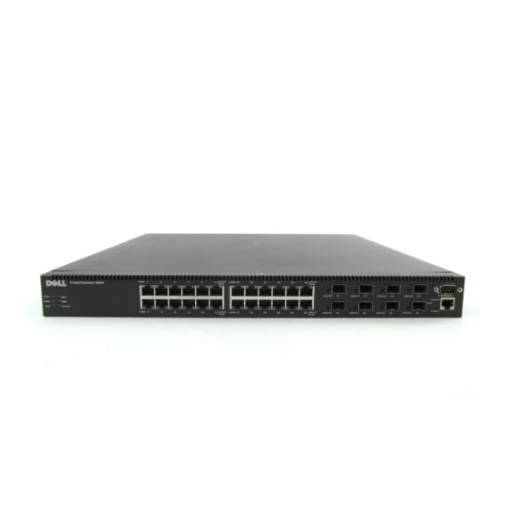
High availability with hot swappable power supplies and cooling fans PowerConnect 6024 The PowerConnect 6024 provides 24 10/100/1000 Base-T RJ-45 ports with eight SFP combo ports that have an auto-sensing mode for speed, flow control, and duplex mode. SFP transceivers are sold separately. -
Page 14: Powerconnect 6024F
The CLI Reference Guide provides information about the CLI commands used to configure the switch. The document provides CLI descriptions, syntax, and default values. Features This section describes the switch’s user-configurable features. For a list of all features, refer to the software version release notes. Port Based Features Virtual Cable Testing (VCT) VCT detects and reports potential copper link cabling issues, such as cable opens or cable shorts. - Page 15 The PowerConnect 6024/6024F enhances auto negotiation by providing port advertisement. Port advertisement allows the system administrator to configure the port speeds advertised. For information about auto negotiation, see "Defining Port Configuration" or "Defining LAG Configuration."...
-
Page 16: Mac Address Supported Features
MAC Address Supported Features MAC Address Support The switch supports up to 16K MAC addresses and reserves specific MAC addresses for system use. Self-Learning MAC Addresses The switch enables MAC addresses to be automatically learned from incoming packets. Automatic Aging for MAC Addresses MAC addresses that have not seen any traffic for a given period are aged out, which prevents the Bridging Table from overflowing. -
Page 17: Vlan Supported Features
GARP VLAN Registration Protocol (GVRP) provides IEEE 802.1Q-compliant VLAN pruning and dynamic VLAN creation on 802.1Q trunk ports. When GVRP is enabled, the switch registers and propagates VLAN membership on all ports that are part of the active underlying Spanning Tree protocol topology. -
Page 18: Spanning Tree Protocol Features
Private VLAN Edge Private VLAN Edge (PVE) ports are a Layer 2 security feature that provides port-based security between adjacent ports within a VLAN. It is an extension of the common VLAN. Traffic from protected ports is sent only to the uplink ports and cannot be sent to other ports within the VLAN. For information about configuring PVE ports, see "Configuring Ports". -
Page 19: Link Aggregation
Link Aggregation Link Aggregation Up to seven ports can combine to form a single Link Aggregated Group (LAG). This enables fault tolerance protection from physical link disruption, higher bandwidth connections and improved bandwidth granularity. A LAG is composed of ports of the same speed, set to full-duplex operation. For information about configuring LAGs, see "Defining LAG Configuration."... - Page 20 Address Resolution Protocol (ARP) In IP routing, routers and Layer 3 switches use various routing protocols to discover network topology and define routing tables. ARP automatically determines Device Next-Hop MAC addresses of systems, including directly attached end systems. Users can override and supplement this by defining additional ARP table entries.
-
Page 21: Layer 3 Features
To overcome unpredictable network traffic and optimize performance, you can apply Quality of Service (QoS) throughout the network to ensure that network traffic is prioritized according to specific criteria. Your switch supports two modes of QoS: basic and advanced. Introduction... -
Page 22: Device Management Features
For information about SNMP Alarms and Traps, see "Defining SNMP Parameters." Web Based Management You can manage the system from any web browser. The switch contains an embedded web server that serves HTML pages that you can use to monitor and configure the system. - Page 23 Trivial File Transfer Protocol (TFTP) PowerConnect 6024/6024F supports boot image, firmware and configuration upload/download via TFTP. Remote Monitoring Remote monitoring (RMON) is an extension to the SNMP that provides comprehensive network traffic monitoring capabilities (as opposed to SNMP, which allows network device management and monitoring).
-
Page 24: Security Features
Passwords for SSH, Telnet, HTTP, HTTPS and SNMP access are assigned security features. For more information about password management, see "Managing Passwords". TACACS+ TACACS+ provides centralized security for validation of users accessing the switch. TACACS+ provides a centralized user management system, while still retaining consistency with RADIUS and other authentication processes. - Page 25 RADIUS Client RADIUS is a client/server-based protocol in which the server maintains a user database, that contains per-user authentication information, such as user name, password and accounting information. For information about defining RADIUS settings, see "Configuring RADIUS Settings." Secure Shell (SSH) is a protocol that provides a secure, remote connection to a device. This connection provides functionality that is similar to an inbound telnet connection.
- Page 26 Introduction...
-
Page 27: Hardware Description
SFP connection. When a connector is inserted in the SFP port, the SFP port is active, unless a Base-T port copper connector of the of the same number is inserted and has a link. Figure 2-1. PowerConnect 6024 with 24 10/100/1000 Base-T Ports The switch automatically detects the difference between crossed and straight through cables on RJ-45 ports. -
Page 28: Powerconnect 6024F
Ports 1-16 are designated as SFP ports, and ports 17-24 are designated as combo ports. The port numbers are shown in the figure below. For information about how the ports function, see the port description for the PowerConnect 6024. Figure 2-2. PowerConnect 6024F with 24 SFP Ports... -
Page 29: Hardware Components
17.32 x 18.11 x 1.73 inch (W x D x H). Power Supplies Your switch is shipped with two internal power supplies. You can verify operation by observing the LEDs. See "System LEDs" for information. To replace a power supply: Remove the faulty power supply unit by removing its screw in the back panel and pulling it out. -
Page 30: Reset Button
When you connect to a different power source, the probability of the switch failing in the event of a power outage decreases. Reset Button The reset button, located on the front panel, manually resets the switch. Ventilation System There are two fans in the system. You can verify operation by observing the LEDs. See "System LEDs"... -
Page 31: Sfp Port Leds
SFP Port LEDs Figure 2-5 illustrates the SFP port LEDs that are next to each SFP port. Figure 2-5. SFP Port LEDs SFP LEDs Table 2-1 contains SFP port LED definitions: Table 2-1. SFP Port LEDs Definitions Color Green Flashing Green 10/100/1000 Base-T Port LEDs Each 10/100/1000 Base-T port has two LEDs. -
Page 32: System Leds
Table 2-2 contains 10/100/1000 Base-T port LED definitions. Table 2-2. 10/100/1000 Base-T Port Definitions Color Speed Green Amber Link Green Flashing Green Amber Flashing Amber System LEDs The system LEDs, located on the left side of the front panel, provide information about the power supplies, fans, thermal conditions, and diagnostics. - Page 33 Figure 2-7. System LEDs Table 2-3 contains system LED definitions. Table 2-3. System LED Definitions Color Fan 1 Green Fan 2 Green PWR1 Green Definition Fan 1 is present and operating. Fan 1 is present, but not operating. Fan 1 is not present. Fan 2 is present and operating.
- Page 34 Table 2-3. System LED Definitions Color PWR2 Green Dia (Diagnostic) Flashing Green Green Thermal Hardware Description Definition Power Supply 2 is present and operating. Power Supply 2 is present, but not operating. Power Supply 2 is not present. A diagnostics test is currently in progress.
-
Page 35: Cable, Port, And Pinout Information
This section describes the switch’s physical interfaces and provides information about cable connections. Stations are connected to the switch’s ports through the physical interface ports on the front panel. For each station, the appropriate mode (Half/Full Duplex, Auto) is set. -
Page 36: Pin Connections For Sfp Interfaces
Table 3-1. RJ-45 Pin Connections for 10/100/1000 Base T TxRx 2- TxRx3+ TxRx 3- TxRx 4+ TxRx 4- Pin Connections for SFP Interfaces Figure 3-2 illustrates an SFP connector, and Table 3-2 shows the pin assignments for an optional SFP connector. Figure 3-2. -
Page 37: Serial Cable Connection
Serial Cable Connection You can use serial cables (null-modem) to connect the switch to a terminal for initial setup and configuration (You can also use a PC running terminal emulation software.). The switch’s serial cable is female to female DB-9 crossover cable (see Figure 3-3). -
Page 38: Connecting The Switch To A Terminal
Connecting the Switch to a Terminal Connect the null modem (serial) cable to the terminal (console) ASCII DTE RS-232 connection. Connect the interface cable to the switch’s serial port connection (see Figure 3-4). Cable, Port, and Pinout Information Management Console Port Signal... -
Page 39: Ac Power Connection
Figure 3-4. Serial Connection to Switch AC Power Connection Using a 5-foot (1.5 m) standard power cable with safety ground connected, connect the power cable to the AC main socket located on the rear panel (see Figure 3-5). Connect the power cable to a grounded AC outlet. - Page 40 Figure 3-5. AC Power Connection to Switch Cable, Port, and Pinout Information...
-
Page 41: Using Dell Openmanage Switch Administrator
Starting the Application Open a web browser. Enter the switch’s IP address (as defined in the CLI) in the address bar and press. For information about assigning an IP address to a switch, see "Initial Configuration." When the Enter Network Password window displays, enter a user name and password. - Page 42 By dragging the vertical bar to the right, you can expand the tree area to view a full name of a component. Using Dell OpenManage Switch Administrator...
-
Page 43: Using The Switch Administrator Buttons
You can also view components by expanding a feature in the tree view. The information buttons provide access to information about the switch and access to Dell Support. For more information, see "Information Buttons." Using the Switch Administrator Buttons Information Buttons Table 4-2. -
Page 44: Device Management Buttons
Show Neighbor’s Info Displays the Neighbors List from the Neighbors Table Draw Clear Log Reset Test Now Defining Fields User-defined fields can contain 1-159 characters, unless otherwise noted on the Dell OpenManage Switch Administrator Web page. All characters may be used except for the following: • • •... -
Page 45: Accessing The Switch Through The Cli
• Accessing the Switch Through the CLI The switch can be managed over a direct connection to the console port or via a Telnet connection. For information about out-of-band management ports, see "Out-of-Band Management Port." Using the CLI is similar to entering commands on a Linux system. If access is via a Telnet connection, ensure the device has an IP address defined and that the workstation used to access the device is connected to the device prior to beginning using CLI commands. -
Page 46: Using The Cli
At the prompt type enable and press. When a password prompt displays, enter the password and press . The Privileged EXEC mode prompt displays as the device host name followed by #. For example: console# Using Dell OpenManage Switch Administrator... -
Page 47: Global Configuration Mode
To return from Global Configuration mode to Privileged EXEC mode, type the exit command or use thecommand. The following example illustrates how to access Global Configuration Mode and return back to the Privileged EXEC Mode: console# console#configure console(config)#exit console# Using Dell OpenManage Switch Administrator... -
Page 48: Interface Configuration Mode
Out-of-Band-Ethernet — Contains commands for managing and configuring the management connections. CLI Examples CLI commands are provided as configuration examples. For a full description of the CLI commands, including examples, refer to your switch’s CLI Reference Guide. Using Dell OpenManage Switch Administrator... -
Page 49: Configuring The Switch
Performing other functions is described later in this section. NOTICE: Before proceeding, read the release notes for this product. You can download the release notes from support.dell.com. Configuring the Switch... - Page 50 Figure 5-1. Installation and Configuration Jobflow Press Esc Startup Menu (Special functions) Reboot Configuring the Switch Connect Device and Console Power on Loading program from flash to RAM Enter Wizard Initial Configuration: IP Address, Subnetmask, Users Basic Security configuration Advanced Configuration:...
-
Page 51: General Configuration Information
Configure each port for the highest-level operational mode that both ports can support If connecting a port of the switch to the network interface card (NIC) of a workstation or server that does not support auto-negotiation or is not set to auto-negotiation, both the switching port and the NIC must be manuallyet with the Web browser interface or CLI commands to the same speed and duplex mode. -
Page 52: Terminal Connection Configuration
Closing the device does not return the default baud rate. It must be specifically configured. NOTE: The baud rate setting of the console is not saved in the general configuration file of the switch. It is directly stored in the non-volatile memory device of the switch. -
Page 53: Other Configuration Requirements
ASCII terminal (or emulation) connected to the serial port (cross-cable) in the front of the unit • Assigned IP address for the switch for device remote control use with Telnet, SSH, and so forth NOTE: The configuration process defines only one port. - Page 54 Dram first PTR is Dram second block size is Dram second PTR is Flash size is: 16M Tuning File info. Ver: 0.2.80 Creation date: Aug 20 2003 11:20:13 Configuring the Switch Ver. 1.0.1.06 Date : 256M bytes : 235520K bytes : 0x1800000...
- Page 55 18-May-2003 16:24:42 %LINK-W-Down: 18-May-2003 16:24:42 %LINK-W-Down: After the switch boots successfully, a system prompt appears (console>) and you can use the local terminal to begin configuring the switch. However, before configuring the switch, ensure that the software version installed on the device is the latest version. If it is not the latest version, download and install the latest version.
-
Page 56: Configuration Overview
Configuration Overview Your switch supports a 10/100 Mbps Ethernet Out-of-Band (OOB) management port that is connected directly to the device. This port supports system-administrator management applications. The Out-of-Band port is treated as an IP interface to the system, and all management interfaces are available over this port. - Page 57 The wizard automatically assigns the highest access level [Privilege Level 15] to this account. You can use Dell Network Manager or other management interfaces to change this setting later, and to add additional management system later.
- Page 58 Next, an IP address is setup. The IP address is defined on the OOB port. This is the IP address you use to access the CLI, Web interface, or SNMP interface for the switch. To setup an IP address: Please enter the device IP address(A.B.C.D): Please enter the IP subnet mask (A.B.C.D or /nn):...
- Page 59 [Y] is entered the following is displayed: Configuring SNMP management interface. Configuring user account... Configuring IP and subnet... Thank you for using Dell Easy Setup Wizard. You will now enter CLI mode. Wizard Step 6 The CLI prompt is displayed.
-
Page 60: Advanced Configuration
• Assigning Dynamic IP Addresses (on an Out-of-Band Port) console# configure console(config)# interface out-of-band-eth console(config-oob)# ip address dhcp hostname dell console(config-oob)# exit console(config)# exit The interface receives the IP address automatically. To verify the IP address, enter the show ip interface command at the system prompt as shown in the following example. -
Page 61: Receiving An Ip Address From A Bootp Server
DHCP on an interface that connects to the same DHCP server, or to one with an identical configuration. In this instance, the switch retrieves the new configuration file and boots from it. The switch then enables DHCP as instructed in the new configuration file, and the DHCP instructs it to reload the same file again. -
Page 62: Security Management And Password Configuration
A priority of "15" must be set to enable access and configuration rights to the device. Although user names can be assigned privilege level 15 without a password, it is recommended to always assign a password. If there is no specified password, privileged users can access the Web interface with any password Configuring the Switch... - Page 63 To configure an initial SSH password, enter the following commands: console(config)# aaa authentication login default line console(config)# aaa authentication enable default line console(config)# line ssh console(config-line)# login authentication default console(config-line)# enable authentication default console(config-line)# password jones. at the password george at the password Configuring the Switch...
-
Page 64: Contents
XModem, which is a data transfer protocol for updating back-up configuration files. To download a boot file using XModem: Enter the command console# xmodem: boot. The switch is ready to receive the file via the XModem protocol and displays text similar to the following: console# copy xmodem: boot... -
Page 65: Software Download Through Tftp Server
TFTP server. The TFTP server must be configured before downloading the software. The switch boots and runs when decompressing the system image from the flash memory area where a copy of the system image is stored. When a new image is downloaded, it is saved in the other area allocated for the additional system image copy. - Page 66 Enter the command reload. The following message is displayed: console# reload This command will reset the whole system and disconnect your current session. Do you want to continue (y/n) [n] ? Enter Y to reboot the switch. Configuring the Switch...
-
Page 67: Boot Image Download
Enter Y to reboot the switch. Sample Configuration Process This section provides the basic steps required to establish a remote network management connection with the switch. This section does not explain the various configurations available on the switch or the relevant commands. Configuring the Switch... -
Page 68: Device Setup Requirements
This section also describes accessing a switch for the first time with the default configuration and definitions. If a previously entered configuration causes problems, the startup-configuration file— which is the configuration of device when powered up—should be erased and device rebooted, see "Device Default Settings."... - Page 69 115,200 is the default baud rate for new device. The device may have another baud rate. If using the 115,200 baud rate does not result in viewing the device terminal, try other baud rate. Use an F2F null modem cable to connect the workstation to the switch. Connect the device power cord and power up the device.
- Page 70 HW version is 00.01.64 Base Mac address is: 00:00:b0:16:00:00 Dram size is Dram first block size is Dram first PTR is Dram second block size is Configuring the Switch Date 13-Aug-2003 Ver. 1.0.1.06 Date : 256M bytes : 235520K bytes...
- Page 71 18-May-2003 16:24:41 %Box-W-FAN-STAT-CHNG: FAN# 1 status changed - operational. 18-May-2003 16:24:41 %Box-I-FAN-STAT-CHNG: FAN# 2 status changed - operational. console> 18-May-2003 16:24:41 %DELL-I-STATUS: The product global status has chan ged from ok to non-critical at time 900. 18-May-2003 16:24:42 %LINK-W-Down: 18-May-2003 16:24:42 %LINK-W-Down:...
-
Page 72: Device Default Settings
Enter the enable command at the console to enter the Privileged EXEC screen mode as follows: console>enable console# Connect the management station (PC) to the device via one of the Ethernet ports, or through a network connected to the device, using a CAT5 Cable. Configuring the Switch SYSTEM RESET *****************... - Page 73 0.0.0.0.0.0.0.0 50.1.1.100 console(config)# Ping the management station from the switch to make sure that connectivity has been achieved. Wait 30 seconds for port to be in STP forwarding before pinging the management station. Management station IP is (in this example) 50.1.1.2:...
- Page 74 Define a user name and password to allow privileged level 15 device access for a remote user (HTTP and HTTPS). In this example the user name and password is "Dell," user name is "Dell," and the privilege level is 15. Privilege levels range from 1-15, with 15 being the highest level. Level 15 access is the only level of access for the Web interface.
-
Page 75: Setting The Management Station Ip Address
Web browser interface, and others. Setting the Management Station IP Address On the management station, click Start→ Settings→ Network and Dial-up Connections. Right-click the network connection that is used for management, and select Properties. The connection properties window is displayed. Configuring the Switch... - Page 76 Figure 5-3. Local Area Connection Properties Window Click Internet Protocol (TCP/IP) and then click Properties. The Internet Protocol (TCP/IP) Properties window is displayed. Configuring the Switch...
-
Page 77: Enabling Telnet Access
Default gateway fields. NOTE: If the management station is connected to a router and not directly to the 6024/6024F switch, the default gateway must be configured as the router interface IP address connected to the management station (which leads to the 6024/6024F switch). - Page 78 Gateway IP Address ----------------------- ----------------------- 10.6.12.1 IP Address ----------------------- ---------------------- --------- 10.6.12.20/24 The switch indicates the Telnet session status: console> 01-Jan-2000 02:39:04 %MSCM-I-NEWTERM: New TELNET connection from 50.1.1.2 01Jan-2000 02:39:11 %MSCM-I-TERMTERMINATED: TELNET connection from 50.1.1.2 terminated Configuring the Switch Type...
-
Page 79: Enabling Web Access (Http Server)
Ensure that the Use a proxy server check box is cleared, and then click OK. Figure 5-5. Local Area Network (LAN) Settings Window Click OK to close the Internet Options window. In the browser window enter the IP previously configured on the device (with or without http:// prefix). Configuring the Switch... - Page 80 Figure 5-6. Logging onto the Web Interface The password authentication window is displayed. Enter the assigned user name and password. The Dell OpenManage Switch Administrator is displayed. NOTE: If no password is defined, any password is accepted. Configuring the Switch...
-
Page 81: Configuring Secure Management Access (Https)
To manage the device securely via the standard Web browser, perform the following: Configure the switch to allow HTTPS server, and to create a security key, use the commands ip https server and crypto certificate generate key-generate:... -
Page 82: Startup Menu Functions
The Enter Network Password window is displayed. Enter the assigned user name and password. The device Dell OpenManage Switch Administrator is displayed. Startup Menu Functions You can perform additional configuration from the Startup menu. To display the Startup menu: During the boot process, after the first part of the POST is completed press... -
Page 83: Download Software
[6] Back Enter your choice or press 'ESC' to exit: The following sections describe the Startup menu options. If no selection is made within 25 seconds (default), the switch times out. Only technical support personnel can operate the Diagnostics Mode. For this reason, the Enter Diagnostic Mode option of the Startup menu is not described in this guide. -
Page 84: Erase Flash Sectors
Enter config as the flash file name. The configuration is erased and the device reboots. Perform the switch’s initial configuration. Erase FLASH Sectors For troubleshooting purposes, you may need to erase flash sectors. If the flash is erased, all software files must be downloaded and installed again. -
Page 85: Password Recovery
The Out-of-Band (OOB)management port is a 10/100-Mbps Ethernet port that can be used to connect directly to the switch to perform system administrator management functions. This port is regarded as a regular IP interface to the system, and all management interfaces are available over this port. -
Page 86: Assigning Static Ip Addresses (On An Out-Of-Band Port)
10.0.0.1 /8 console(config-oob)#ip default-gateway 10.1.1.1 console(config-oob)# Ping via Out-of-Band console#ping oob/10.6.12.25 Copy Image/Boot copy tftp://oob/10.6.12.25/ves_115.dos image copy tftp://oob/10.6.12.25/boot_013.rfb boot IP Default Gateway to Out-of-Band console#configure console(config)#interface out-of-band-eth console(config-oob)#ip default-gateway 10.1.1.10 Configuring the Switch... -
Page 87: Additional Information
Additional Information For more information about configuring Out-of-Band, see "Configuring Out-of-Band (OOB) Management Ports." Configuring the Switch... - Page 88 Configuring the Switch...
-
Page 89: Configuring System Information
The Asset page contains parameters for configuring and viewing general device information, including the system name, location, and contact, the system MAC address for both the switch and the out-of-band management port, system object ID, date, time, and system uptime. - Page 90 System Name — The user-assigned device system nam. System Contact —The contact person name. System Location —The system runninglocation. MAC Address —The MAC address switch . Sys Object ID —The MIB OID. Service Tag —The service reference number used when servicing the device.
- Page 91 Defining System Information Open the Asset page. Define the following fields: System Name, System Contact, System Location, and Asset Tag. Click Apply Changes. The system parameters are applied, and the device is updated. Initiating a Telnet Session Open the Asset page. NOTE: The appropriate telnet parameters are set prior to initiating the telnet session.
-
Page 92: Defining System Time Settings
If the system clock is synchronized with an external SNTP clock and that clock fails, the system clock time source automatically switches to the local hardware clock. The system clock can be configured to automatically switch to Daylight Savings Time. For more information on SNTP, see Configuring SNTP Settings. - Page 93 Time Zone Offset — Defines the difference in hours between Greenwich Mean Time (GMT) and local time. The system clock can be scheduled to automatically switch to Daylight Savings Time (DST) based on a defined period of time in a specific year or a recurring period of time. Use the parameters in the Daylight Savings area to define a period of time in a specific year and use the parameters in the Recurring area to define a recurring period of time.
- Page 94 European — The device clock changes to DST at 1:00 am on the last Sunday in March and reverts to standard time at 1:00 am on the last Sunday in October. This option applies to EU members and other European countries using the EU standard. Other —...
-
Page 95: The Following Is An Example Of Cli Commands
2:00 Configuring System Health Information The System Health page displays physical device information, including information about the switch’s power and ventilation sources. To display the System Health page, click System Health in the tree view. Description Synchronizes the system time with an SNTP server clock. - Page 96 — The power supply is operating normally. — The power supply is not operating normally. Not Present—The power supply is currently not present. Fan—Indicates the fan status. The PowerConnect 6024/6024F has two fans. — The fan is operating normally. — The fan is not operating normally.
-
Page 97: The Following Is An Example Of The Cli Commands
System MAC Address: OOB MAC Address: System Object ID: Type: Main Power Supply Status: Redundant Power Supply Status: Fan 1 Status: Fan 2 Status: Temperature (Celsius): Temperature Sensor Status: Ethernet Routing Switch 0,00:32:04 00:0d:56:2f:45:30 00:00:00:00:00:18 1.3.6.1.4.1.674.10895.3000 PowerConnect 6024 Configuring System Information... -
Page 98: Version Information
Version Information The Versions page contains information about the hardware and software versions currently running. To display the Versions page, click System Figure 6-5). Figure 6-5. Versions The Versions page contains the following fields: Software Version—The current software version running on the device. Boot Version—The current boot version running on the device. -
Page 99: Resetting The Device
The following is an example of the CLI commands: Console# show version SW version 1.0.0.67 ( date Boot version 1.0.0.11 ( date HW version 00.01.64 Resetting the Device You can use the Reset page to reset the device. To open the Reset page, click System Reset in the tree view (see Figure 6-6). -
Page 100: Configuring Sntp Settings
Resetting the Device Using the CLI If you are not already in the Privileged User EXEC mode of the CLI, enter enable. If you want to save any changes made to the running configuration of the device, enter copy running-config startup-config. Enter reload. -
Page 101: Defining Sntp Global Parameters
Polling for Anycast information is used when the server IP address is unknown. If this method is selected, all SNTP servers on the network can send synchronization information . The device is synchronized when it proactively requests synchronization information. The best response (lowest stratum) from the first 3 SNTP servers to respond to a request for synchronization information is used to set the time value. - Page 102 Figure 6-7. SNTP Global Settings The SNTP Global Settings page contains the following fields: Poll Interval (60-86400) — Defines the interval (in seconds) at which the SNTP server is polled for Unicast information. Receive Broadcast Servers Updates — If enabled, listens to the SNTP servers for Broadcast server time information on the selected interfaces.
- Page 103 Defining SNTP Global Parameters Using CLI Commands The following table summarizes the equivalent CLI commands for setting fields displayed in the SNTP Global Settings page. Table 6-5. SNTP Global Parameters CLI Commands CLI Command Description Sets the polling time for the SNTP client sntp client poll timer seconds Enables SNTP Broadcast clients...
-
Page 104: Defining Sntp Authentication Methods
Defining SNTP Authentication Methods The SNTP Authentication page enables SNTP authentication between the device and a SNTP server. The SNTP server is also selected in the SNTP Authentication page. Click System → SNTP→ Authentication in the tree view to open the SNTP Authentication page. Figure 6-8. - Page 105 Figure 6-9. Add Authentication Key Define the fields. Click Apply Changes. The SNTP Authentication Key is added, and the device is updated. Displaying the Authentication Key Table Open the SNTP Authentication page. Click Show All. The Authentication Key Table page opens: Figure 6-10.
-
Page 106: Defining Sntp Servers
Defining SNTP Authentication Settings Using CLI Commands The following table summarizes the equivalent CLI commands for setting fields displayed in the SNTP Authentication page. Table 6-6. SNTP Authentication CLI Commands CLI Command sntp authenticate sntp authentication- key number md5 value sntp trusted-key key-number show sntp... - Page 107 Figure 6-11. SNTP Servers The SNTP Servers page contains the following fields: SNTP Server — Contains a list of user-defined SNTP server IP addresses. Up to eight SNTP servers can be defined. Poll Interval — Enables polling the selected SNTP server for system time information, when enabled.
- Page 108 Last Response — The last time a response was received from the SNTP server. Offset — Timestamp difference between the device’s local clock and the acquired time from the SNTP server. Delay — The amount of time it takes to reach the SNTP server. Remove —...
- Page 109 Modifying an SNTP Server Open the SNTP Servers page. Click Show All. The SNTP Servers Table opens. Select an SNTP Server entry. Modify the relevant fields. Click Apply Changes. The SNTP server information is updated. Deleting the SNTP Server Open the SNTP Servers page. Click Show All.
-
Page 110: Defining Sntp Interfaces
Defining SNTP Interfaces The SNTP Broadcast Interface Table contains fields for setting SNTP on different interfaces. To open the SNTP Broadcast Interface Table, click System→ SNTP→ Interfaces Settings. Figure 6-14. SNTP Broadcast Interface Table The SNTP Broadcast Interface Table contains the following fields: Interface —... - Page 111 Defining SNTP Interface Settings Using CLI Commands The following table summarizes the equivalent CLI commands for setting fields displayed in the SNTP Broadcast Interface Table. NOTE: When defining Anycast or Broadcast interfaces, at least one IP address must be defined. Table 6-8.
-
Page 112: Configuring Out-Of-Band (Oob) Management Ports
Configuring Out-of-Band (OOB) Management Ports This section describes managing the following device features through the Out-of-Band management port. It includes information about the the Out-of-Band remote log server, Out-of- Band default gateway, Out-of-Band IP interface parameters, Out-of-Band TACACS+ server and Out-of-Band RADIUS server. - Page 113 Facility—A user-defined application from which system logs are sent to the remote server. Only one facility can be assigned to a single server. If a second facility level is assigned, the first facility level is overridden. All applications defined for a device use the same facility on a server. The possible field values are local 0, local 1, local 2, local 3, local 4, local 5, local 6 and local 7.
-
Page 114: Defining Out-Of-Band Default Gateways
Table 6-9. Out-of-Band Remote Log Server Settings CLI Commands CLI Command logging oob/ip- address [port port ] [severity level ] [facility f acility ] [description text ] The following is an example of the CLI commands: Console(config)#logging oob/10.2.2.2 local0 description syslog_server_1 Defining Out-of-Band Default Gateways Use the OOB Default Gateway page to assign gateway devices. -
Page 115: Defining Out-Of-Band Ip Interface Parameters
Define an IP address in the Default Gateway field. Click Apply Changes. The Out-of-Band Gateway device is defined, and the device is updated. Table 6-10. Out-of-Band Default Gateway CLI Commands CLI Command Description Defines the Out-of-Band IP Gateway. ip default gateway ip- address The following is an example of the CLI commands:... - Page 116 Figure 6-17. OOB IP Interface Parameters The OOB IP Interface Parameters page contains the following parameters: IP Address—The Out-of-Band interface IP address. Prefix Length—The number of bits that comprise the source IP address prefix, or the network mask of the source IP address. Type—The means by which the Out-of-Band IP interface was created;...
-
Page 117: Configuring Out-Of-Band Tacacs+ Servers
Deleting IP Addresses Open the OOB IP Interface Parameters page. Click Show All. The Interface Parameters Table page opens. Select an IP address in the IP Address drop-down list. Select an entry in the Interface Parameters Table. Check the Remove checkbox. Click Apply Changes. - Page 118 TACACS+ servers can be defined on in-band ports using TACACS+ Settings page or on the out- of-band port. The TACACS+ protocol ensures network integrity through encrypted protocol exchanges between the device and TACACS+ server. The OOB TACACS+ Settings page contains both user-defined and the default TACACS+ settings for the Out-of-Band management port.
- Page 119 Status — The connection status between the device and the TACACS+ server. The possible field values are: Connected — There is currently a connection between the device and the TACACS+ server. Not Connected — There is not currently a connection between the device and the TACACS+ server.
- Page 120 The TACACS+ Table page opens. Select a TACACS+ Table entry. Select the Remove check box. Click Apply Changes. The TACACS+ server is removed, and the device is updated. TACACS+ Servers Using CLI Commands Defining The following table summarizes the CLI commands for working with fields in the OOB TACACS+ Settings page.
- Page 121 The following is an example of the CLI commands: Console(config)# tacacs-server host oob/172.16.8.1 key abc Console (config)# end Console# show tacacs Device Configuration -------------------- IP address Status ---------- --------- No TACACS server is configured. OOB host Configuration IP address Status ---------- --------- 172.16.8.1...
-
Page 122: Configuring Out-Of-Band Radius Servers
Configuring Out-of-Band RADIUS Servers The OOB RADIUS Settings page contains both user-defined and the default RADIUS settings for the Out-of-Band management port. For more information on RADIUS servers, see "Configuring TACACS+ Settings." To open the OOB RADIUS Settings page, click System→ Out-of-Band Port→ RADIUS in the tree view (see OOB RADIUS Settings, Figure 6-19). - Page 123 Key String (0-128 Characters)—Key string used for authenticating and encrypting all RADIUS communications between the device and the RADIUS server. This key must match the RADIUS encryption. If no host-specific value is specified, the global value applies to each host. Source IP Address—IP address of device accessing the RADIUS server.
- Page 124 Select a RADIUS server and check the Remove checkbox. Click Apply Changes. The RADIUS server is removed from the RADIUS Servers list. Defining RADIUS Servers Using CLI Commands The following table summarizes the CLI commands for working with fields in the OOB RADIUS Settings page.
-
Page 125: Managing Logs
Managing Logs The Logs page contains links to various log pages. To display the Logs page, click System→ Logs in the tree view. Global Log Parameters The Global Log Parameters page contains fields for enabling logs globally, and fields for defining log parameters. - Page 126 Critical — The third highest warning level. A critical log is saved if a critical device malfunction occurs, for example, two device ports are not functioning, while the rest of the device ports remain functional. Error — A device error has occurred, such as if a port is offline. Warning —...
- Page 127 Enabling Global Logs Using the CLI The following table summarizes the equivalent CLI commands for working with fields displayed in the Global Log Parameters page. Table 6-14. Global Log Parameters CLI Commands CLI Command Description Enables error message logging. logging on Logs messages to a syslog server.
-
Page 128: Ram Log Table
RAM Log Table The RAM Log Table contains information about specific RAM (cache) log entries, including the time the log was entered, the log severity, and a description of the log. To display the RAM Log Table, click System→ Logs→ RAM Log in the tree view (see Figure 6-21). Figure 6-21. -
Page 129: Log File Table
Viewing the RAM Log Table Using the CLI The following table summarizes the equivalent CLI commands for viewing fields displayed in the RAM Log Table. Table 6-15. RAM Log Table CLI Commands CLI Command Description Displays the state of logging and the syslog messages show logging stored in the internal buffer. - Page 130 Figure 6-22. Log File Table The Log File Table page contains the following fields: • Log Index—The Log Number within the Log File Table. • Log Time—The time at which the log was entered in the Log File Table. • Severity—The log severity.
-
Page 131: Remote Log Server
The following is an example of the CLI commands: Console # show logging file Console Logging: Level info. Console Messages: 0 Dropped. Buffer Logging: Level info. Buffer Messages: 30 Logged, 30 Displayed, 200 Max. File Logging: Level error. File Messages: 1 Logged, 30 Dropped. 1 messages were not logged 10-Jan-2003 16:53:44 :%MSCM-I-NEWTERM: New TELNET connection from 143.166.155.18... - Page 132 Figure 6-23. Remote Log Server Settings The Remote Log Server Settings page contains the following fields: Available Servers — Servers to which logs can be sent. UDP Port (1-65535) — The UDP port from which the logs are sent. The default value is 514. Facility —...
-
Page 133: Defining Ip Addressing
Click Apply Changes. The log settings are saved, and the device is updated. Defining a New Server Open the Remote Log Server Settings page. Click Add to display the Add a Log Server page. NOTE: Before adding a new server, determine the IP address of the remote log server. Complete the fields in the dialog and click Apply Changes. -
Page 134: Defining Ip Interfaces
Defining IP Interfaces The IP Interface Parameters page contains parameters for assigning IP addresses to interfaces. To open the IP Interface Parameters page, click System the tree view. Figure 6-24. IP Interface Parameters The IP Interface Parameters page contains the following fields: IP Address —... - Page 135 Remove — When checked, removes the interface from the IP Address drop-down menu. Adding an IP Interface Open the IP Interface Parameters page. Click Add to open the Add a Static IP Interface page. Figure 6-25. Add a Static IP Interface Complete the fields on the page.
- Page 136 Defining IP Interface Parameters Using CLI Commands The following table summarizes the equivalent CLI commands for working with fields on the IP Interface Parameters page. Table 6-18. IP Interface Parameters CLI Commands CLI Command ip address ip-address {mask | prefix-length} no ip address [ ip- address ] show ip interface...
-
Page 137: Defining Dhcp Ip Interface Parameters
Defining DHCP IP Interface Parameters The DHCP IP Interface page specifies the DHCP clients connected to the device. To open the DHCP IP Interface page, click System→ IP Addressing→ DHCP IP Interface in the tree view. Figure 6-26. DHCP IP Interface The DHCP IP Interface page contains the following fields: Interface —... -
Page 138: Configuring Domain Name Systems
Modifying a DHCP IP Interface Open the DHCP IP Interface page. Modify the fields. Click Apply Changes. The entry is modified, and the device is updated. Deleting a DHCP IP Interface Open the DHCP IP Interface page. Click Show All to open the DHCP IP Interface Table page. Select a DHCP client entry. - Page 139 Figure 6-27. Domain Naming System (DNS) The Domain Naming System (DNS) page contains the following fields: DNS Status — Enables or disables translating DNS names into IP addresses. DNS Server — Contains a list of DNS servers. DNS servers are added in the Add DNS Server page. DNS Server Currently Active —...
- Page 140 The Add DNS Server page contains the following fields: DNS Server — Specifies the DNS server’s IP address. DNS Server Currently Active — Indicates the currently active DNS server. Set DNS Server Active — Select the check box to define the DNS server as the active DNS server.
-
Page 141: Defining Default Domains
Configuring DNS Servers Using the CLI Commands The following table summarizes the CLI commands for configuring DNS servers. Table 6-20. DNS Server CLI Commands CLI Command Description Sets the available name servers. Up to eight name ip name-server servers can be set. server-address Removes a name server. - Page 142 [ name ] The following is an example of the CLI commands: Console(config)# ip domain-name dell.com Configuring System Information Description Defines a default domain name that the software uses to complete unqualified host names.
-
Page 143: Mapping The Domain Host
Mapping the Domain Host The Host Name Mapping page provides parameters for assigning an IP address to a static host name. The Host Name Mapping page provides one IP address per host. To open the Host Name Mapping page, click System→ IP Addressing→ Host Name Mapping. Figure 6-31. - Page 144 Figure 6-32. Add Host Name Mapping Define the relevant fields. Click Apply Changes. The IP address is mapped to the host name, and the device is updated. Displaying the Host Names Mapping Table Open the Host Name Mapping page. Click Show All. The Host Name Mapping Table opens: Figure 6-33.
- Page 145 Table 6-22. Domain Host Name CLI Commands CLI Command Description ip host name address Defines the static host name-to-address mapping in the host cache. Removes the name-to-address mapping. no ip host name Deletes entries from the host name-to-address clear host { name | cache.
-
Page 146: Enabling Arp Proxy
Address Resolution Protocol (ARP) is a TCP/IP protocol that converts IP addresses into physical addresses. The ARP Proxy page allows network managers to enable ARP Proxy on the switch. To open the ARP Proxy page, click System→ IP Addressing→ ARP Proxy in the tree view. -
Page 147: Defining Arp Settings
Enabling ARP Proxy Using CLI Commands The following table contains the CLI commands for enabling the ARP Proxy. Table 6-23. ARP Proxy CLI Commands CLI Command Description Enables ARP proxy ip proxy-arp Disables ARP proxy no ip proxy-arp The following is an example of the CLI commands: Console (config)# ip proxy-arp Defining ARP Settings Use the ARP Settings page to define ARP parameters for an IP interface. - Page 148 The ARP Settings page contains the following fields: Global Settings — Select this option of activate the fields for ARP global settings. ARP Entry Age Out (0- 40000000) — For all devices, the amount of time (seconds) that pass between ARP requests about an ARP table entry. After this period, the entry is deleted from the table.
- Page 149 Figure 6-36. Add ARP Entry Page Select an interface and complete the fields in the page. Click Apply Changes. The ARP Table static entry is added, and the device is updated. Modifying an ARP Table Entry Open the ARP Settings page. Select a table entry.
-
Page 150: Defining Dhcp Relay Parameters
Configuring ARP Using the CLI Commands The following table contains the CLI commands for configuring the ARP. Table 6-24. ARP Settings CLI Commands CLI Command arp ip_addr hw_addr {ethernet interface- number | vlan vlan-id | port-channel number | out-of-band-eth oob- interface} arp timeout show arp... - Page 151 Figure 6-37. DHCP Relay Enabling DHCP Relay Open the DHCP Relay page. Select Enable from the DHCP Relay drop-down menu. Click Apply Changes. The DHCP Relay entry is added to the DHCP Relay TTable. Adding a DHCP Relay Entry Open the DHCP Relay page. Click Add to open the Add DHCP Server page.
- Page 152 Deleting a DHCP Relay Table Entry Open the DHCP Relay page. Click Show All to open the DHCP Servers Table page. Select a DHCP Server and check Remove. Click Apply Changes. The entry is deleted, and the device is updated. Defining DHCP Relay Servers Using CLI Commands The following table contains the CLI commands for defining DHCP Relay servers.
-
Page 153: Configuring Udp Relay
Configuring UDP Relay UDP Relay allows UDP packets to reach other networks. This feature enables browsing from workstations to servers on different networks. To open the UDP Relay page, click System→ IP Addressing→ UDP Relay in the tree view. Figure 6-38. UDP Relay The UDP Relay page contains the following fields: Source IP Interface —... - Page 154 Table 6-26. UDP Port Allocations UDP Port Number Destination Address — The IP interface that receives UDP packet relays. If this field is 0.0.0.0, UDP packets are discarded. If this field is 255.255.255.255, UDP packets are flooded to all IP interfaces.
- Page 155 Click Apply Changes. The DHCP Server is added to the DHCP Relay Table. Modifying a UDP Relay Table Entry NOTE: If UDP relay is enabled, but no UDP port number is specified, the device by default forwards UDP Broadcast packets for the following services: IEN-116 Name Service (port 42), DNS (port 53), NetBIOS Name Server (port 137), NetBIOS Datagram Server (port 138), TACACS Server (port 49), and Time Service (port 37) Open the UDP Relay page.
-
Page 156: Running Cable Diagnostics
Running Cable Diagnostics Use the Diagnostics page to perform virtual cable tests for copper and fiber optics cables. To open the Diagnostics page, click System→ Diagnostics in the tree view. The Diagnostics page contains links to diagnostics pages for copper cable and optical transceivers. Viewing Copper Cable Diagnostics Use the Virtual Cable Test for Copper Cables page to perform tests on copper cables. - Page 157 Open Cable — The cable is open. Short Cable — A short has occurred in the cable. OK — The cable passed the test. Fiber Cable — A fiber cable is connected to the port. Cable Fault Distance — The distance from the port where the cable error occurred. Last Update —...
-
Page 158: Viewing Optical Transceiver Diagnostics
The following is an example of the CLI commands: Console# show copper-ports cable-length Port Length [meters] ---- --------------- g1 < 50 g2 Copper not active g3 110-140 g4 Fiber NOTE: The cable length returned by the VCT is an approximation in the ranges of up to 50 meters, 50m- 80m, 80m-110m, 110m-120m, or more than 120m. - Page 159 Figure 6-40. Optical Transceiver Diagnostics The Optical Transceiver Diagnostics page contains the following fields: Port — The port IP address on which the cable is tested. Temperature — The temperature (C) at which the cable is operating. Voltage — The voltage at which the cable is operating. Current —...
-
Page 160: Managing Device Security
Performing Fiber Optic Cable Tests Using CLI Commands The following table contains the CLI command for performing fiber optic cable tests. Table 6-29. Fiber Optic Cable Test CLI Command CLI Command show fiber-ports optical- transceiver [ interface ] [ detailed ] The following is an example of the CLI command: console# show fiber-ports optical-transceiver The following columns appear on the screen:... - Page 161 Management access can be separately defined for each type of management access method, including, Web (HTTP), Secure web (HTTPS), Telnet, and SNMP. Access to different management methods may differ between user groups. For example, User Group 1 can access the device only via an HTTPs session, while User Group 2 can access the device via both HTTPs and Telnet sessions.
- Page 162 Adding an Access Profile Open the Access Profiles page. Click Add Profile to open the Add an Access Profile page. Figure 6-42. Add an Access Profile The Add an Access Profile page contains the following fields: Access Profile Name — User-defined name for the access profile. Rule Priority —...
- Page 163 Enter the profile name in the Access Profile Name text box. Complete the fields and click Apply Changes. The new access profile is added, and the device is updated. Activating an Access Profile Open the Access Profiles page. Select an access profile from the list. Check the Set Access Profile Active check box.
- Page 164 Select a rule. Check the Remove check box and click Apply Changes. The rule is deleted, and the device is updated. Defining Access Profiles Using CLI Commands The following table summarizes the equivalent CLI commands for configuring access profiles. Table 6-30. Access Profile CLI Commands CLI Command management access-list name NOTE:...
-
Page 165: Defining Authentication Profiles
The following is an example of the CLI commands: Console (config)# management access-list mlist Console (config-macl)# permit ethernet g1 Console (config-macl)# permit ethernet g9 Console (config-macl)# exit Console# show management access-class Management access-class is enabled, using access list mlist Defining Authentication Profiles User authentication occurs locally and on an external server. - Page 166 Optional Methods — User authentication methods. Possible options are: None — No user authentication occurs. Local — User authentication occurs at the device level; the device checks the user name and password for authentication. RADIUS — User authentication occurs at the RADIUS server. For more information about RADIUS servers, see "Configuring RADIUS Settings."...
-
Page 167: Selecting Authentication Profiles
Click Apply Changes. The entry is removed. Configuring an Authentication Profile Using CLI Commands The following table summarizes the equivalent CLI commands for defining authentication profiles. Table 6-31. Authentication Profile CLI Commands CLI Command aaa authentication login {default | list-name } method1 [ method2 ...] no aaa authentication login {default | list-name }... - Page 168 Figure 6-45. Select Authentication The Select Authentication page contains the following fields: Console — Authentication profiles used to authenticate console users. Telnet — Authentication profiles used to authenticate Telnet users. Secure Telnet (SSH) — Authentication profiles used to authenticate Secure Shell (SSH) users. SSH provides clients secure and encrypted remote connections to a device.
- Page 169 Local, RADIUS — Authentication first occurs locally. If authentication cannot be verified locally, the RADIUS server authenticates the management method. If the RADIUS server cannot authenticate the management method, the session is blocked. Local, TACACS+ — Authentication first occurs locally. If authentication cannot be verified locally, the TACACS+ server authenticates the management method.
- Page 170 Applying an Authentication Profile to Secure Telnet (SSH) Sessions Open the Select Authentication page. Select an authentication profile in the Secure Telnet (SSH) field. Click Apply Changes. Secure Telnet (SSH) sessions are assigned authentication profiles. Assigning HTTP Sessions an Authentication Sequence Open the Select Authentication page.
- Page 171 Table 6-32. Access Methods CLI Commands CLI Command ip http authentication method1 [ method2... ] ip https authentication method1 [ method2... ] show authentication methods The following is an example of the CLI commands: Console# show authentication methods Login Authentication Method Lists ---------------------------------- Default : Local...
-
Page 172: Managing Passwords
Managing Passwords Password management provides increased network security and improved password control. Passwords for SSH, Telnet, HTTP, HTTPS, and SNMP access are assigned security features, including: • Defining minimum password lengths • Password expiration • Preventing frequent password reuse • Locking out users out after failed login attempts To open the Password Management page, click To open the Password Management page, click System→... - Page 173 NOTE: The user is notified to change the password prior to expiry. The Web users do not see this notification. Enable Login Attempts (1-5)— When selected, enables locking a user out of the device when a faulty password is used a defined number of times. For example, if the number of login attempts has been defined as five and the user attempts to log on five times with an incorrect password, the device locks the user out on the sixth attempt.
-
Page 174: Defining The Local User Databases
Console# show passwords configuration Minimal length: 8 Aging: 120 days History: 2 Lock-out: Disabled Defining the Local User Databases Use the Local User Database page to define passwords, access rights for users and reactivate users whose accounts have been suspended. To open the Local User Database page, click System→... - Page 175 Confirm Password — Confirms the user-defined password. Remove — When selected, removes users from the User Name list. Assigning Access Rights to a User Open the Local User Database page. Select a user in the User Name field. Define the fields. Click Apply Changes.
-
Page 176: Defining Line Passwords
Assigning Users Using CLI Commands The following table summarizes the equivalent CLI commands for viewing fields displayed on the Local User Database page. Table 6-34. Local User Database CLI Commands CLI Command username name [password password ] [privilege level ] [encrypted] set username name active... - Page 177 Figure 6-48. Line Password The Line Password page contains the following fields: Line Password for Console/Telnet/Secure Telnet — The line password for accessing the device via a console, Telnet, or Secure Telnet session. Confirm Password — Confirms the new line password. The password appears in the ***** format. Defining Line Passwords Open the Line Password page.
-
Page 178: Defining Enable Password
The following is an example of the CLI commands: Console (config-line)# password **** Defining Enable Password The Modify Enable Password page sets a local password to control access to different privilege levels (1-15). To open the Modify Enable Password page, click System→ Management Security→ Enable Password in the tree view. -
Page 179: Configuring Tacacs+ Settings
Table 6-36. Enable Password CLI Commands CLI Command enable password [level level ] password [encrypted] show users accounts The following is an example of the CLI commands: Console (config)# enable password level 15 dell Console# show users accounts Username Privilege --------- --------- Dell 1515... - Page 180 The TACACS+ Settings page contains both user-defined and the default TACACS+ settings for the inband management port. To open the TACACS+ Settings page, click System→ Management Security→ TACACS+ in the tree view. Figure 6-50. TACACS+ Settings The TACACS+ Settings page contains the following fields: Host IP Address —...
- Page 181 Status — The connection status between the device and the TACACS+ server. The possible field values are: Connected — There is currently a connection between the device and the TACACS+ server. Not Connected — There is not currently a connection between the device and the TACACS+ server.
- Page 182 TACACS+ Server from the TACACS+ Servers List Deleting a Open the TACACS+ Settings page. Click Show All. The TACACS+ Table opens. Select a TACACS+ Table entry. Select the Remove check box. Click Apply Changes. The TACACS+ server is removed, and the device is updated. TACACS+ Servers Using CLI Commands Defining The following table summarizes the equivalent CLI commands for configuring fields displayed in...
- Page 183 Table 6-37. TACACS+ Settings CLI Commands CLI Command show tacacs+ [ ip-address ] Displays configuration and statistics for a The following is an example of the CLI commands: Console(config)# tacacs-server host 171.16.8.1 port 49 key abc Console(config)# end Console# show tacacs Device Configuration -------------------- IP address...
-
Page 184: Configuring Radius Settings
Telnet Access • Web Access • Console to Switch Access The RADIUS Settings page contains both user-defined and the default RADIUS settings. To open the RADIUS Settings page, click System Management→ Security→ RADIUS in the tree view. Figure 6-51. RADIUS Settings The RADIUS Settings page contains the following fields: IP Address —... - Page 185 Timeout for Reply (1-30) — Amount of the time in seconds the device waits for an answer from the RADIUS server before timing out. Possible field values are 1 - 30. Three is the default value. If no host-specific value is specified, the global value applies to each host. Click Use Default to use the default value.
- Page 186 Modifying the RADIUS Server settings Open the RADIUS Settings page. Click Show All to display the RADIUS Servers List. Modify the fields in the dialog. Click Apply Changes. The RADIUS Server settings are modified, and the device is updated. Deleting a RADIUS Server for the RADIUS Servers List Open the RADIUS Settings page.
-
Page 187: Defining Snmp Parameters
The following is an example of CLI commands: Console (config)# radius-server timeout 5 Console (config)# radius-server retransmit 5 Console (config)# radius-server deadtime 10 Console (config)# radius-server key dell-server Console (config)# radius-server host 196.210.100.1 auth-port 127 timeout 20 Console# show radius-servers... -
Page 188: Defining Snmp Global Parameters
• Timeliness — Protects against message delay or message redundancy. The SNMP agent compares incoming message to the message time information. • Key Management — Defines key generation, key updates, and key use. The device supports SNMP notification filters based on Object IDs (OID). OIDs are used by the system to manage device features. - Page 189 Authentication Notifications — Enables or disables the device sending SNMP traps when authentication fails. Enabling SNMP Notifications Open the Global Parameters page. Select Enable in the SNMP Notifications field. Click Apply Changes. SNMP notifications are enabled, and the device is updated. Enabling Authentication Notifications Open the Global Parameters page.
- Page 190 The following is an example of CLI commands: Console (config)# snmp-server enable traps Console (config)# snmp-server trap authentication Console (config)# end Console# show snmp Community-String ------------ public private private OOB management stations Community-String ------------ private Traps are enabled. Authentication trap is enabled. Trap-Rec-Address 192.122.173.42 OOB trap receivers...
-
Page 191: Defining Snmp Views
Defining SNMP Views SNMP views provide or block access to device features or feature aspects. For example, a view can be defined which states that SNMP group A has read-only access to routing, while SNMP group B has read-write access to routing. Feature access is granted via the MIB name or MIB Object ID. Use the SNMP View Setting page to define SNMP views. - Page 192 Figure 6-54. Add A View Define the relevant fields. Click Apply Changes. The SNMP view is added, and the device is updated. Displaying the View Table Open the SNMP View Setting page. Click Show All. The View Table page opens: Figure 6-55.
- Page 193 Click Apply Changes. The SNMP view is deleted, and the device is updated. Defining SNMP Views Using CLI Commands The following table summarizes the equivalent CLI commands for defining fields displayed in the SNMP View Setting page. Table 6-40. SNMP View CLI Commands CLI Command Description Creates or updates a view entry.
-
Page 194: Defining Snmp Access Control
Defining SNMP Access Control The Access Control Group page provides information for creating SNMP groups, and assigning SNMP access privileges. Groups allow network managers to assign access rights to specific device features or features aspects. The Out-of-Band port is treated as a separate device when using SNMP features. Views can be limited to Out-of-Band MIBs, device MIBs or to all MIBs. - Page 195 Authentication — Authenticates SNMP messages without encrypting them. Privacy — Authenticates SNMP messages and encrypts them. Operation — Defines group access rights. The possible field values are: Read — Select a view that restricts management access to viewing the contents of the agent. If no view is selected, all objects except the community-table, SNMPv3 user and access tables can be viewed.
- Page 196 Displaying the Access Table Open the Access Control Group page. Click Show All. The Access Table page opens: Figure 6-58. Access Table Deleting a Group Open the Access Control Group page. Click Show All. The Access Table opens. Select a group. Check the Remove checkbox.
-
Page 197: Assigning Snmp User Security
Table 6-41. SNMP Access Control CLI Commands CLI Command Description Configure a new Simple Network Management snmp-server group Protocol (SNMP) group, or a table that maps groupname {v1 | v2 | SNMP users to SNMP views. v3 {noauth | auth | priv}} [read readview ] [write writeview ] [notify... - Page 198 Figure 6-59. SNMPv3 User Security Model (USM) The SNMPv3 User Security Model (USM) page contains the following fields: Engine ID — Identifies the remote SNMPv3 enabled device to which the selected user is connected. Remote Engine ID — Indicates that the user is configured on a remote SNMPv3 enabled device.
- Page 199 SHA Key — Users are authenticated using the HMAC-SHA-96 authentication level. The user should enter authentication and privacy keys. Password (0-32 Characters) — Modifies the user defined password for the group. Passwords can contain a maximum of 32 characters. Passwords are defined only if the authentication method is MD5 or SHA Password.
- Page 200 Figure 6-61. SNMPv3 User Security Model Table Deleting a User Security Model Table Entry Open the SNMPv3 User Security Model (USM) page. Click Show All. The SNMPv3 User Security Model Table page opens. Select an entry. Check the Remove check box. Click Apply Changes.
-
Page 201: Defining Communities
Table 6-42. SNMP User CLI Commands CLI Command Description Configures a new SNMP V3 user. snmp-server user username groupname [remote engineid- strin g][auth-md5 password | auth-sha password | auth-md5- key md5-des-key | auth-sha-key sha-des- key ] Displays the configuration of users. show snmp users [ username ] Console (config)# snmp-server user John auth-md5 1234... - Page 202 Figure 6-62. SNMPv1, 2 Community The SNMPv1, 2 Community page contains the following fields: OOB Management Station — Select this checkbox to create a separate SNMP community for the Out-of-Band port. If this checkbox is not selected, the device is accessed by the management station via the inband ports.
- Page 203 View Name — Contains a list of user-defined SNMP views Advanced — Contains a list of user-defined groups. When SNMP Advanced mode is selected, the SNMP access control rules comprising the group are enabled for the selected community. The Advanced mode also enables SNMP groups for specific SNMP communities. The SNMP Advanced mode is defined only with SNMPv3.
-
Page 204: Defining Snmp Notification Filters
{router | oob}] show snmp The following is an example of CLI commands: Console (config)# snmp-server community dell ro 10.1.1.1 Defining SNMP Notification Filters The Notification Filter page permits filtering traps based on OIDs. Each OID is linked to a device feature or a feature aspect. - Page 205 Figure 6-64. Notification Filter The Notification Filter page contains the following fields: Notification Filter Name — Contains a list of user-defined notification filters. A notification filter name can contain a maximum of 30 characters. New Object Identifier Subtree — The OID for which notifications are sent or blocked. If a filter is attached to an OID, traps or informs are generated and sent to the trap recipients.
- Page 206 Figure 6-65. Add Filter Define the relevant fields. Click Apply Changes. The new filter is added, and the device is updated. Displaying the Filter Table Open the Notification Filter page. Click Show All. The Filter Table page opens: Figure 6-66. Filter Table Removing a Filter Open the Notification Filter page.
-
Page 207: Defining Snmp Notification Recipients
Configuring Notification Filters Using CLI Commands The following table summarizes equivalent CLI commands for defining fields displayed in the Notification Filter page. Table 6-44. SNMP Notification Filter CLI Commands CLI Command Description Creates or updates an SNMP notification filter. snmp-server filter filter-name oid-tree {included | excluded} Displays the configuration of SNMP... - Page 208 Figure 6-67. Notification Recipients The Notification Recipients page contains the following fields: Recipient IP — Contains a user-defined list of notification recipients IP addresses. Notification Type — The type of notification sent. The possible field values are: Trap — Traps are sent. Inform —...
- Page 209 SNMPv3 — SNMP version 3 is enabled for the selected recipient. The possible field values are: User Name — Contains a list of users. Select one to generate notifications. Security Level — The security level attached to notifications. The possible field values are: No Authentication —...
- Page 210 Figure 6-68. Add Notification Recipient Define the relevant fields. Click Apply Changes. The notification recipient is added, and the device is updated. Displaying the Notification Recipients Tables Open Notification Recipients page. Click Show All. The Notification Recipients Table page open: Figure 6-69.
- Page 211 Deleting Notification Recipients Open the Notification Recipients page. Click Show All. The Notification Recipients Tables page open. Select one or more notification recipients in the SNMPV1,2 Notification Recipient and/or SNMPv3 Notification Recipient Tables. Click Apply Changes. The recipients are deleted, and the device is updated. Defining SNMP Notification Recipients Using CLI Commands The following table summarizes the equivalent CLI commands for defining fields displayed in the Notification Recipients page.
- Page 212 The following is an example of CLI commands: Console (config)# snmp-server host 12.1.1.1 Dell-community Console (config)# end Console# show snmp Community-String Community-Access ---------------- ---------------- Community-String Group name ---------------- ---------- OOB management stations Community-String Community-Access ---------------- ---------------- Community-String Group name ---------------- ---------- Traps are enabled.
-
Page 213: Managing Files
Version 3 notifications Target Type Username Address -------- ---- -------- OOB Notification Receivers Target Type Username Address -------- ---- -------- Managing Files Use the File Management page to manage device software, the image file, and the configuration files. Files can be downloaded or uploaded via a TFTP server. Management File Overview The management file structure consists of the following files: •... -
Page 214: Downloading Files
To open the File Management page, click System→ File Management in the tree view. Downloading Files The File Download From Server page contains fields for downloading the software from the TFTP server to the device. The image file can also be downloaded from the File Download from Server page. - Page 215 Active Image — Image file that is currently active. Active Image After Reset — The image file that is active after the device is reset. Possible values are as follows: Image 1 — The Image 1 file is active after device is reset. Image 2 —...
- Page 216 Downloading Files Using CLI Commands The following table summarizes the equivalent CLI commands for defining fields displayed in the File Download From Server page. Table 6-46. Download CLI Commands CLI Command copy source-url destination-url The following is an example of the CLI commands: Console # copy tftp://172.16.101.101/file1 image Accessing file 'file1' on 172.16.101.101...
- Page 217 Figure 6-71. File Upload to Server The File Upload to Server page contains the following fields: Firmware Upload — Indicates that the firmware file is uploaded. If Firmware Upload is selected, the Configuration Upload fields are grayed out. Configuration Upload — Indicates that the configuration file is uploaded. If Configuration Upload is selected, the Firmware Upload fields are grayed out.
-
Page 218: Copying Files
Configuration Upload via OOB—Indicates that the Configuration file is uploaded via the out-of- band management port. Uploading Files Open the File Upload to Server page. Define the applicable fields in the page. Click Apply Changes. The software is uploaded to the server. Uploading Files Using CLI Commands The following table summarizes the equivalent CLI commands for defining fields displayed on the File Upload to Server page. - Page 219 Figure 6-72. Copy Files The Copy Files page contains the following fields: Copy Configuration — Specifies that a configuration file should be copied. Source — The configuration source file (running, startup, backup) from which the file is copied. Destination — The destination configuration file (running, startup, backup) to which the file is copied.
-
Page 220: Defining Advanced Settings
Table 6-48. Copy File CLI Commands CLI Command copy source-url destination-url delete startup-config The following is an example of the CLI commands: Console# delete startup-config Defining Advanced Settings Use Advanced Settings to set miscellaneous global attributes of the device. The changes to these attributes are applied only after the device is reset. - Page 221 The General Settings page contains the following fields: Current — Maximum number of entries. After Reset— Maximum number of entries after the device is reset. By entering a value in this column, memory is allocated to the field table. Max RAM Log Entries (20-400) — Maximum number of RAM Log table entries. The default value is 200 entries.
- Page 222 Configuring System Information...
-
Page 223: Configuring Switch Information
Use the Network Security page to set network security through both access control lists and locked ports. To open the Network Security page, select Switch→ Network Security. The Network Security page provides links that enable you to configure port based authentication, port security, IP based ACLs, MAC based ACLs and ACL bindings. -
Page 224: Configuring Port Based Authentication
Advanced Port Based Authentication also enables VLAN based authentication. Specific VLANs in the switch are always available, even if specific ports attached to the VLAN are unauthorized. For example, Voice over IP does not require authentication, while data traffic requires authentication. - Page 225 The field value is in seconds. The field default is 30 seconds. Resending EAP Identity Request (1-65535) — Defines the amount of time that lapses before EAP requests are resent. The field value is in seconds. The field default is 30 seconds. Configuring Switch Information...
- Page 226 Click Show All. The Port Based Authentication Table opens. Select the interface in the Copy Parameters from field. Select the Copy to check box to define the interfaces to which the Port based authentication parameters are copied. Configuring Switch Information...
- Page 227 Sets the time for the retransmission of packets to dot1x timeout the authentication server. server-timeout seconds Sets the time for the retransmission of an EAP dot1x timeout supp- request frame to the client. timeout seconds device Configuring Switch Information...
- Page 228 ---------- Auto Auto Auto Force-auth Configuring Switch Information Description Sets the number of seconds that the device waits for a response to an EAP - request/identity frame, from the client, before resending the request. Displays 802.1X status for the device or for the specified interface.
-
Page 229: Configuring Advanced Port Based Authentication
The Multiple Hosts page provides information for defining advanced port based authentication settings for specific ports. To open the Multiple Hosts page, click Switch → Network Security → Multiple Hosts. Figure 7-3. Multiple Hosts The Multiple Hosts page contains the following fields: Port —... - Page 230 Multiple Hosts page. Table 7-2. Multiple Hosts CLI Commands CLI Command dot1x multiple-hosts Allows multiple hosts (clients) on an 802.1X- Configuring Switch Information Description authorized port that has the dot1x port-control interface configuration command set to auto.
-
Page 231: Authenticating Users
Console(config-if)# dot1x multiple-hosts Authenticating Users The Authenticated Users page displays user port access lists. To open the Authenticated Users page, click Switch → Network Security → Authenticated Users. Figure 7-5. Authenticated Users The Authenticated Users page contains the following fields: User Name —... -
Page 232: Configuring Port Security
When a packet is received on a locked port, and the packet’s source MAC address is not tied to that port (either it was learned on a different port, or is unknown to the system), the Configuring Switch Information Description Displays 802.1X users for the device. - Page 233 Set Port — Enables locking the port. When a port is locked, all the current addresses that had been dynamically learned by the switch on that port, are transformed to static MAC addresses. When the port is unlocked, they are removed from the static list.
- Page 234 Table 7-4. Locked Port Security CLI Commands CLI Command port security [forward | discard | discard-shutdown] [trap seconds ] show ports security [ethernet interface | port-channel port- channel-number ] Configuring Switch Information Description Disables new address learning on an interface. Displays the port-lock status.
-
Page 235: Defining Ip Based Acls
The total number of ACEs that can be defined in all ACLs together is 1024. Use the Add ACE to IP Based ACL page to define IP-based ACEs. To open the Add ACE to IP Based ACL page, select Switch→ Network Security→ IP Based ACL. Action... - Page 236 A wild card mask of 255.255.255.255 indicates that no bit is important. A wildcard of 0.0.0.0 indicates that all the bits are important. Dest. IP Address — Matches the destination port IP address to which packets are addressed to the ACE. Configuring Switch Information...
- Page 237 Figure 7-9. Add IP Based ACL Enter the ACL Name. Check the New ACE Priority check box and define all of the fields in the page. Click Apply Changes. The IP based ACL is defined, and the device is updated. Configuring Switch Information...
- Page 238 Open the Add ACE to IP Based ACL page, and select the ACL to be operated upon from the ACL Name drop-down menu. Click Show All. The ACEs Associated with IP-ACL page opens. Check the Remove ACL check box Click Apply Changes. Configuring Switch Information...
- Page 239 } [dscp dscp number | ip-precedence ip-precedence ] show access-lists [ name ] The following is an example of the CLI commands: Console(config)# ip access-list Dell Console(config-ip-al)# permit rsvp 12.1.1.1 0.0.0.0 any dscp 56 Console(config-ip-al)# deny any 192.1.1.10 0.0.0.255 any Console# show access-lists IP access list one permit ip host 12.1.1.1 any...
-
Page 240: Defining Mac Based Acls
The Add ACE to MAC Based ACL page allows network administrators to define a MAC- based ACL. For an explanation of ACLs, see "Defining IP based ACLs." To open the Add ACE to MAC Based ACL page, select Switch→ Network Security→ MAC based ACL. - Page 241 Modifying a MAC based ACE Open the Add ACE to MAC Based ACL page. Select an ACL in the ACL Name field. Modify the required fields. Click Apply Changes. The fields are modified, and the device is updated. Configuring Switch Information...
- Page 242 The MAC-based ACL is removed, and the device is updated. Assigning MAC based ACEs to ACLs Using the CLI Commands The following table summarizes the equivalent CLI commands for assigning MAC based ACEs to ACLs as displayed in the Add ACE to MAC Based ACL page. Configuring Switch Information...
-
Page 243: Configuring Acl Binding
When an ACL is bound to an interface, all the ACE rules that have been defined are applied to the selected interface. Use the ACL Bindings page to assign ACL lists to classification methods and interfaces. To open the ACL Bindings page, select Switch→ Network Security→ ACL Binding. Description Creates Layer 2 MAC ACLs, and enters to MAC-Access list configuration mode. - Page 244 The ACL is attached to the interface. Removing an Entry from the ACL Bindings Table Open the ACL Bindings page. Click Show All to display the ACL Bindings Table. Check the Remove check box for the entry that you want to remove. Configuring Switch Information...
- Page 245 Defines the match criterion to show class-map [ class-map- name ] The following is an example of the CLI commands: Console (config)# class-map class1 match-all Console (config-cmap)# match access-group dell Description Creates class maps and enters the class-map configuration mode. classify traffic.
-
Page 246: Configuring Ports
To open the Ports page Select Switch→ Ports. Defining Port Configuration Use the Port Configuration page to define port parameters. To open the Port Configuration page, click Switch→ Ports→ Port Configuration in the tree view. Figure 7-13. Port Configuration The Port Configuration page contains the following fields: Port —... - Page 247 1000 Full- Indicates that the port is advertising a 1000 mbps speed and full Duplex mode setting. Current Advertisement — The port advertises its speed to its neighbor port to start the negotiation process. The possible field values are those specified in the Admin Advertisement field. Configuring Switch Information...
- Page 248 Hubs and switches are deliberately wired opposite the way end stations are wired, so that when a hub or switch is connected to an end station, a straight through Ethernet cable can be used, and the pairs are match up properly. When two hubs/switches are connected to each other, or two end stations are connected to each other, a crossover cable is used ensure that the correct pairs are connected.
- Page 249 Enables auto negotiation operation for the speed and duplex parameters of a given interface. Enables Back Pressure on a given interface. Configures the Flow Control on a given interface. Enables automatic crossover on a given interface or Port-channel. Configuring Switch Information...
- Page 250 Console (config-if)# back-pressure Console (config-if)# flowcontrol on Console (config-if)# mdix auto Console (config-if)# exit Console (config)# exit Console> set interface active ethernet g9 Configuring Switch Information Description Displays the configuration for all configured interfaces. Displays the status for all configured interfaces.
- Page 251 Enable Link Back Mdix State Pressure Mode ----- ----- Disabled Off Disabled Off Disabled Off Link Back State Pressure ------ ------- Unknown Present Unknown Present Unknown Present Unknown Present Admin Back State Pressure ----- -------- Disabled Disabled Configuring Switch Information...
-
Page 252: Defining Lag Configuration
(LAG). LAGs are often called trunks or aggregate links. Use the LAG Configuration page to configure LAGs parameters. Your switch supports up to seven ports per LAG, and seven LAGs per system. If port configuration is modified while a port is a LAG member, the configuration change is only effective after the port is removed from the LAG. - Page 253 Admin Flow Control — Enables or disables flow control or enables the auto negotiation of flow control on the LAG. Current Flow Control — The user-designated Flow Control setting. Defining LAG Parameters Open the LAG Configuration page. Select a LAG in the LAG field. Define the available fields. Configuring Switch Information...
- Page 254 Console# show interfaces port-channel Channel Port ---------------------------------------------- Ch 1 Active Ch 2 Active Ch 3 Inactive g8 Configuring Switch Information Description Enters the interface configuration mode of a specific port-channel. Associates a port with a Port-channel. Displays Port-channel information (which ports are members of that port-channel, and whether they are currently active or not).
-
Page 255: Enabling Storm Control
Forwarded message responses can overload network resources and/or cause the network to time out. Your switch measures the incoming broadcast/multicast packet rate per port and discards packets when the rate exceeds the defined value. Storm control is enabled per device, by defining the packet type and the rate the packets are transmitted. - Page 256 The following is an example of the CLI commands: Console(config)# port storm-control include-multicast Console(config)# interface ethernet g1 Console(config-if)# port storm-control broadcast enable Configuring Switch Information Description Enables the device to count multicast packets together with broadcast packets. Enables broadcast storm control.
-
Page 257: Defining Port Mirroring Sessions
• All packets are transmitted tagged from the destination port. • All the TX packets should be monitored to the same port. To open the Port Mirroring page, click Switch→ Ports→ Port Mirroring in the tree view. 100000 Disabled Disabled... - Page 258 Remove — When checked, removes the port mirroring session. Adding a Port Mirroring Session Open the Port Mirroring page. Click Add to display the Add Source Port page. Select the source port from the Source Port drop-down menu. Configuring Switch Information...
-
Page 259: Configuring Address Tables
The static and dynamic address tables can be sorted by interface, VLAN, and interface type. In addition, addresses can be added to the static and dynamic address tables. To open the Address Tables page, click Switch→ Address Table in the tree view. Description Starts a port monitoring session. -
Page 260: Defining Static Addresses
The Static Address page contains a list of static MAC addresses. A static address can be added and removed from the Static MAC Address Table. To open the Static Address page, click Switch→ Address Table→ Static Address in the tree view. - Page 261 Table 7-12. Static Address CLI Commands CLI Command bridge address mac-address {ethernet interface | port- channel port-channel- number } [permanent | delete-on-reset | delete- on-timeout | secure] Description Adds a static MAC-layer station source address to the bridge table. Configuring Switch Information...
-
Page 262: Viewing Dynamic Addresses
The Dynamic Address Table also contains information about the aging time before a dynamic MAC address is removed from the table. To open the Dynamic Address Table, click Switch→ Address Tables→ Dynamic Addresses Table in the tree view. Configuring Switch Information... - Page 263 Define the Address Aging field. Click Apply Changes. The aging time is modified, and the device is updated. Querying the Dynamic Address Table Open the Dynamic Address Table page. Define the parameter by which to query the Dynamic Address Table. Configuring Switch Information...
- Page 264 The following is an example of the CLI commands: Console (config)# bridge aging-time 300 Console (config)# exit Console# show bridge address-table Aging time is 300 sec Configuring Switch Information Description Displays classes of dynamically created entries in the bridge-forwarding database.
-
Page 265: Configuring Garp
GARP defines a set of devices interested in a given network attribute, such as VLAN or multicast address. To open the GARP page, click Switch→ GARP in the tree view. Defining GARP Timers The GARP Timers page contains parameters for enabling GARP on the device. To open the GARP Timers page, click Switch→... - Page 266 Table 7-14 summarizes the equivalent CLI commands for defining GARP timers as displayed in the Garp Timers page. Table 7-14. GARP Timer CLI Commands CLI Command garp timer {join | leave | leaveall} timer_value Configuring Switch Information Description Adjusts the GARP application join, leave, and leaveall GARP timer values. The possible...
-
Page 267: Configuring The Spanning Tree Protocol
For information on configuring MSTP, see Defining the Multiple Spanning Tree. To open the Spanning Tree page, click Switch→ Spanning Tree in the tree view. Defining STP Global Settings The Spanning Tree Global Settings page contains parameters for enabling STP on the device. - Page 268 The possible field values are Filtering and Flooding. The default value is Flooding. Priority (0-65535) — The bridge priority value. When switches or bridges are running STP, each are assigned a priority. After exchanging BPDUs, the switch with the lowest priority value becomes the root bridge. The default value is 32768.
- Page 269 Hello Time (1-10) — The switch Hello time, which indicates the amount of time in seconds a root bridge waits between configuration messages. The default value is 2. Max Age (6-40) — The switch maximum age time, which indicates the amount of time in seconds a bridge waits before implementing a topological change.
- Page 270 Configures handling BPDU packets when the spanning tree is disabled on an interface. Configures the spanning tree priority. Configures the spanning tree bridge Hello Time, which is how often the switch broadcasts Hello messages to other switches. Configures the spanning tree bridge maximum age.
-
Page 271: Defining Stp Port Settings
DSBL TRUE Defining STP Port Settings Use the STP Port Settings page to assign STP properties to individual ports. To open the STP Port Settings page, click Switch→ Spanning Tree→ Port Settings in the tree view. Designated Cost Cost Bridge Id... - Page 272 Listening — The port is currently in the listening mode. The port cannot forward traffic nor can it learn MAC addresses. Learning — The port is currently in the learning mode. The port cannot forward traffic, however, it can learn new MAC addresses. Configuring Switch Information...
- Page 273 Modify the Priority, Fast Link, Path Cost, and the Fast Link fields. Click Apply Changes. The STP port parameters are modified, and the device is updated. Displaying the STP Port Table Open the STP Port Settings page. Click Show All. The STP Port Table opens. Configuring Switch Information...
- Page 274 Prio.Nbr Cost Sts Cost Bridge ID -------- ------- 128.1 Spanning tree enabled Type: point-to-point (configured : auto) Configuring Switch Information Description Disables spanning tree on a specific port. Configures the spanning tree path cost for a port. Configures port priority.
-
Page 275: Defining Stp Lag Settings
Defining STP LAG Settings Use the STP LAG Settings page to assign STP aggregating ports parameters. To open the STP LAG Settings page, click Switch→ Spanning Tree→ LAG Settings in the tree view. Figure 7-22. STP LAG Settings The STP LAG Settings page contains the following fields: Select a LAG —... - Page 276 The STP LAG parameters are modified, and the device is updated. Defining STP LAG Settings Using CLI Commands The following table contains the CLI commands for defining STP LAG settings. Table 7-17. STP LAG Settings CLI Commands CLI Command spanning-tree Configuring Switch Information Description Enables spanning tree.
- Page 277 Number of transitions to forwarding state: 0 Description Configures the spanning tree path cost for a port. Configures port priority. Displays spanning tree configuration. Enables Port Fast mode. Designated Cost Cost Bridge Id 35000 32768 00:00:b0:11:00:00 Prio.Nbr 96 25 Configuring Switch Information...
-
Page 278: Defining The Rapid Spanning Tree
Rapid Spanning Tree Protocol (RSTP) detects and uses network topologies that allow a faster convergence of the spanning tree, without creating forwarding loops. To open the Rapid Spanning Tree (RSTP) page, click Switch→ Spanning Tree→ Rapid Spanning Tree in the tree view. Figure 7-23. Rapid Spanning Tree (RSTP) Page Interface —... -
Page 279: Defining The Multiple Spanning Tree
MSTP provides a differing load balancing scenario. For example, while port A is blocked in one STP instance, the same port is placed in the Forwarding State in another STP instance. The MSTP Settings page allows defining up to sixteen MSTP instances for the device. Description Overrides the default link-type setting. Configuring Switch Information... - Page 280 A configuration consists of the name, revision and region to which your device belongs. To open the MSTP Settings page, click Switch → Spanning Tree → MSTP Region Configuration in the tree view.
- Page 281 {add | remove} vlan vlan-range name string revision value spanning-tree mst instance-id port- priority priority Description Enters the MST Configuration mode. Maps VLANs to the MST instance. Sets the configuration name. Sets the configuration revision number Sets the port priority. Configuring Switch Information...
- Page 282 Console(config-mst)# instance 2 add vlan 21-30 Console(config-mst)# name region1 Console(config-mst)# revision 1 Console(config-mst)# show pending Pending MST configuration Configuring Switch Information Description Sets the device priority for the specified spanning tree instance. Sets the number of hops in an MST region before the BPDU is discarded and the information held for a port is aged.
-
Page 283: Defining Mstp Interface Settings
Defining MSTP Interface Settings Use the MSTP Interface Setting page to assign MSTP settings to specific interfaces. To open the MSTP Interface Setting page, click Switch → Spanning Tree → MSTP Interface Setting in the tree view. Figure 7-26. MSTP Interface Setting The MSTP Interface Setting page contains the following parameters: Instance ID —... - Page 284 Forward Transitions — Number of times the port changed to the forwarding state. Remain Hops — Indicates the number of hops remaining to the next destination. Viewing the MSTP Interface Table Open the MSTP Interface Setting page. Click Show All. The MSTP Interface Table page opens: Configuring Switch Information...
- Page 285 ###### MST 0 Vlans Mapped: 1-9, 21-4094 CST Root ID Priority 32768 Address 00:01:42:97:e0:00 Path Cost 20000 Description Sets the path cost of the port for MST calculations Sets the device priority for the specified ST instance. Displays the MST configuration. Configuring Switch Information...
-
Page 286: Configuring Vlans
Broadcast and Multicast traffic is confined to the originating group. To display the VLAN page, click Switch Defining VLAN Membership Use the VLAN Membership page to define VLAN groups. To open the VLAN Membership page, click Switch Configuring Switch Information Max Age 20 sec Forward Delay 15 sec... - Page 287 VLAN Membership Table The VLAN Membership Table contains parameters for assigning VLAN membership to ports. Your switch supports up to 4095 VLANs. However, you can actually create only 4062 VLANs because: • VLANs 4064 through 4094 are reserved by the device for the internal operational usage, •...
- Page 288 { vlan-range } Creates a VLAN. name string The following is an example of the CLI commands: console (config)#interface vlan 1972 console (config-if)#name Marketing Configuring Switch Information Description Enters the interface configuration (VLAN) mode. Adds a name to a VLAN.
- Page 289 Open the VLAN Membership page. Click the VLAN ID or VLAN Name option button and select a VLAN from the drop-down menu. Check the Remove VLAN check box. Click Apply Changes. The VLAN is deleted, and the device is updated. Configuring Switch Information...
-
Page 290: Defining Vlan Port Settings
The port default VLAN ID (PVID) is configured on the VLAN Port Settings page. All untagged packets arriving to the device are tagged by the ports PVID. To open the VLAN Port Settings page, click Switch Figure 7-29. VLAN Port Settings Page Port —... - Page 291 It is also not possible to enable or disable ingress filtering on an access port. Assigning Ports to VLAN Groups Using CLI Commands The following table contains the CLI commands for assigning ports to VLAN groups. Configuring Switch Information...
- Page 292 Console (config-if)# switchport general allowed vlan add 1,2,5,6 tagged Console (config-if)# switchport general acceptable-packet-types tagged-only Configuring Switch Information Description Configures a port VLAN membership mode. Defines the port as a member of the specified VLAN, and the VLAN ID as the "port default VLAN ID (PVID)".
-
Page 293: Defining Vlan Lag Settings
VLANs can either be composed of individual ports or of LAGs. Untagged packets entering the switch are tagged with the LAGs ID specified by the PVID. To open the VLAN LAG Settings page, click Switch→ VLAN→ LAG Settings in the tree view. - Page 294 Configuring Switch Information Description Configures a port VLAN membership mode. Defines the port as a member of the specified VLAN, and the VLAN ID as the port default VLAN ID (PVID). Configure the Port VLAN ID (PVID) when the interface is in general mode.
-
Page 295: Defining Vlan Protocol Groups
The Protocol Group page contains information regarding protocol names and the VLAN Ethernet type. Interfaces can be classified as a specific protocol based interface. The classification places the interface into a protocol group.To open the Protocol Group page, click Switch→ VLAN→ Protocol Group in the tree view. -
Page 296: Adding Protocol Ports
Console (config-vlan)# map protocol ip-arp protocols-group 213 Adding Protocol Ports The Protocol Port page adds interfaces to protocol groups. To open the Protocol Port page, click Switch→ VLAN→ Protocol Port in the tree view. Configuring Switch Information Description Adds a special protocol to a named group of protocols, which may be used for protocol-based VLAN assignment. - Page 297 Complete the fields in the dialog and click Apply Changes. The new VLAN protocol group is added to the Protocol Port Table, and the device is updated. Defining Protocol Ports Using CLI Commands The following table contains the CLI commands for defining Protocol Ports. Configuring Switch Information...
-
Page 298: Configuring Gvrp
GVRP VLANs is 255) and expected to be configured. The GVRP Global Parameters page enables GVRP globally. You can also enable GVRP on a per- interface basis. To open the GVRP Global Parameters page, click Switch→ VLAN→ GVRP Parameters in the tree view. - Page 299 Open the GVRP Global Parameters page. Select Enable in the GVRP Global Status field for the desired interface. Select Enable in the GVRP Registration field. Click Apply Changes. GVRP VLAN Registration is enabled on the port, and the device is updated. Configuring Switch Information...
- Page 300 Console (config-if)# gvrp enable Console (config-if)# gvrp vlan-creation-forbid Console (config-if)# gvrp registration-forbid Console> show gvrp configuration GVRP Feature is currently Enabled on the device. Configuring Switch Information Description Enables GVRP globally. Enables GVRP on an interface. Enables or disables dynamic VLAN creation.
- Page 301 Enabled rJIn : Join In Received rLIn : Leave In Received : Leave All Received sJIn : Join In Sent sLIn : Leave In Sent : Leave All Sent Configuring Switch Information Leave All --------- 10000 10000 10000 10000 10000...
-
Page 302: Aggregating Ports
(aggregated group). Aggregating ports multiplies the bandwidth between the devices, increases port flexibility, and provides link redundancy. Your switch supports both static LAGs and Link Aggregation Control Protocol (LACP) LAGs. LACP LAGs negotiate aggregating ports’ links with other LACP ports located on a different device. -
Page 303: Defining Lacp Parameters
Ports added to a LAG lose their individual port configuration. When ports are removed from the LAG, the original port configuration is applied to the ports. Your switch uses a hash function to determine which packets are carried on which aggregated-link member. The hash function statistically load-balances the aggregated link members. The switch considers an Aggregated Link a single logical port. - Page 304 Configuring LACP Parameters Using CLI Commands The following table summarizes the equivalent CLI commands for configuring LACP parameters as displayed in the Link Aggregation page. Table 7-29. LACP Parameters CLI Commands CLI Command lacp system-priority value Configuring Switch Information Description Configures the system priority.
-
Page 305: Defining Lag Membership
LACP PDUs received:2 Defining LAG Membership Your switch supports seven LAG per system, and seven ports per LAG. Use the LAG Membership page to assign ports to LAGs. To open the LAG Membership page, click Switch→ Link Aggregation→ LAG Membership in the tree view. - Page 306 CLI Command interface port-channel port-channel-number channel-group port- channel-number mode {on | auto} Configuring Switch Information Description Enters the interface configuration mode of a specific port-channel. Associates a port with a port-channel. Use the no form of this command to remove the...
-
Page 307: Multicast Forwarding Support
Multicast forwarding allows a single packet to be forwarded to multiple destinations. The L2 Multicast service is based on an L2 switch receiving a single packet addressed to a specific Multicast address. Multicast forwarding creates copies of the packet, and transmits the packets to the relevant ports. - Page 308 Multicast group is accepting members. This creates the Multicast filtering database. Use the Multicast Global Parameters page to enable IGMP Snooping on the device. To open the Multicast Global Parameters page, click Switch→ Multicast Support→ Global Parameters in the tree view.
-
Page 309: Adding Bridge Multicast Address Members
Multicast service groups. The Bridge Multicast Group page permits new multicast service groups to be created. The Bridge Multicast Group page also assigns ports to a specific multicast service address group. To open the Bridge Multicast Group page, click Switch→ Multicast Support→ Bridge Multicast Address in the tree view. Description Enables filtering of Multicast addresses. - Page 310 The following table contains the settings for managing IGMP port and LAG members. Table 7-32. IGMP Port/LAG Members Table Control Settings Port Control Configuring Switch Information Definition Indicates that the port/LAG has joined the Multicast group dynamically in the Current Row.
- Page 311 Toggle a port to S to join the port to the selected multicast group. Toggle a port to F to forbid adding specific multicast addresses to a specific port. Click Apply Changes. The port is assigned to the multicast group, and the device is updated. Configuring Switch Information...
- Page 312 ] [format ip | mac] The following is an example of the CLI commands: console#config console(config)#vlan database console(config-if)#vlan 8 console(config-if)#exit Configuring Switch Information Description Registers MAC-layer multicast addresses to the bridge table, and adds static ports to the group. Forbids adding a specific multicast address to specific ports.
-
Page 313: Assigning Multicast Forward All Parameters
0100.5e02.0203 add ethernet g9 Assigning Multicast Forward All Parameters Use the Bridge Multicast Forward All page to enable attaching ports or LAGs to a switch that is attached to a neighboring Multicast router/switch. Once IGMP Snooping is enabled, multicast packets are forwarded to the appropriate port or VLAN. - Page 314 Table 7-34. Bridge Multicast Forward All Router/Port Control Port Control Blank Attaching a Port to a Multicast Router or Switch Open Bridge Multicast Forward All page. Define the VLAN ID field. Select a port in the Ports table, and assign the port a value.
- Page 315 Click Apply Changes. The port is attached to the multicast router or switch. Attaching a LAG to a Multicast Router or Switch Open Bridge Multicast Forward All page. Define the VLAN ID field. Select a port in the LAGs table, and assign the LAG a value.
-
Page 316: Igmp Snooping
Console (config)# interface VLAN 1 Console (config-if)# bridge multicast forward-all add ethernet g8 IGMP Snooping Use the IGMP Snooping page to add IGMP members. To open the IGMP Snooping page, click Switch→ Multicast Support→ IGMP Snooping in the tree view. Configuring Switch Information... - Page 317 Select the VLAN ID for the device on which you want to enable IGMP snooping. Select Enable in the IGMP Snooping Status field. Complete the fields on the page. Click Apply Changes. IGMP snooping is enabled on the device. Displaying the IGMP Snooping Table Open the IGMP Snooping page. Configuring Switch Information...
- Page 318 Console (config-if)# ip igmp snooping mrouter-time-out 200 Console (config-if)# exit Console (config)# interface vlan 1 Console (config-if)# ip igmp snooping leave-time-out 60 Console (config-if)# exit Configuring Switch Information Description Enables Internet Group Membership Protocol (IGMP) snooping. Enables automatic learning of multicast router ports in the context of a specific VLAN.
- Page 319 IGMP host timeout is 300 sec IGMP Immediate leave is disabled. IGMP leave timeout is 10 sec IGMP mrouter timeout is 200 sec Automatic learning of multicast router ports is enabled Console> show igmp-snooping mrouter VLAN Ports ------- ----------------------------------------- Configuring Switch Information...
- Page 320 Configuring Switch Information...
-
Page 321: Configuring Routing
Devices in different subnetworks communicate with each other using a Layer 3 router between the VLANs. Routing is enabled by default on your switch. However, at least one IP interface must be configured for the switch to begin routing network traffic. Routes are either statically configured, or are configured using Routing Information Protocol (RIP) or Open Shortest Path First (OSPF). - Page 322 Figure 8-1. IP Forwarding Page Maximum Equal Cost Multipaths (ECMP) — The ECMP value, which must be defined when forwarding IP packets. The ECMP value indicates how many paths from the router to a network are available. The possible value range is 1-4. For example, a value of 1 indicates that there is only one path to the network.
- Page 323 Viewing IP Forwarding Using the CLI Commands The following table contains the CLI commands for viewing IP Forwarding. Table 8-1. IP Forwarding CLI Commands CLI Command Description Displays the current state of the routing table. show ip route [address]< ip- address >...
-
Page 324: Configuring Ip Static Routes
Configuring IP Static Routes Use the IP Static Route page to define static routes. To open the IP Static Route page, click Router→ Global Routing Parameters→ IP Static Route in the tree view. Figure 8-2. IP Static Route Page Destination IP Address — Static route’s destination IP network. Network Mask—The destination network mask for this route. - Page 325 The Destination IP Address and Network Mask designates the remote network address. The Next Hop is the address of a router directly connected to your switch. The Destination IP Address is the address of the host. The Next Hop should be filled in as 0.0.0.0.
-
Page 326: Configuring Vrrp
The Virtual Router Redundancy Protocol (VRRP) page sets the switch’s VRRP routing parameters. To open the Virtual Router Redundancy Protocol (VRRP) page, click Router →... - Page 327 MAC, and accepts packets associated with the virtual IP addresses (only if the router owns the associated IP address). Initialize — The router waits for a startup event. When the startup event is received, the router transits to the appropriate state. Backup —...
- Page 328 Define the fields. See "Configuring VRRP" for information about the fields. NOTE: VRRP interfaces must be defined before the admin state can be Enabled. Click Apply Changes. The new VRRP interface is added, and the device is updated. NOTE: If an illegal virtual IP address is entered, a warning will display, but the virtual router will be added.
- Page 329 Console(config-if)# vrrp 45 ip 172.16.1.1 172.16.2.1 Console(config-if)# vrrp 45 up Console(config-if)# vrrp 45 timer 100 Console(config-if)# vrrp 45 priority 150 Console(config-if)# vrrp 45 source-ip 168.192.1.1 Console(config-if)# vrrp 45 authentication Dell Console(config-if)# vrrp 45 preempt Console(config-if)# exit Console(config)# exit Description Defines the source IP address (primary IP address) used for Virtual Router Redundancy Protocol (VRRP) messages on an interface.
-
Page 330: Configuring Md5 Routing Authentication
Configuring MD5 Routing Authentication MD5 keys are used by the Message Digest-5 Authentication Algorithm. Start and end times, for both sending and receiving, can be defined for each key. Keys that are active and expire at the reset times can be configured. Interfaces that are inter-communicating must have the same Key ID. If key times overlap on the send side, the device uses the key with the latest start time. - Page 331 Stop Generating At — Date and time the protocol packets are no longer forwarded with MD5 keys. The Stop Generate field format is Month Day Year At: Hour Minute Second. If Forever is selected, no limit is set for accepting traffic with MD5 keys. Remove —...
- Page 332 Select an entry in the Key ID field. Check the Remove check box. Click Apply Changes. The MD5 Key is deleted, and the device is updated. Configuring MD5 Authentication Using the CLI Commands The following table contains the CLI commands for configuring MD5 Authentication. Table 8-4.
-
Page 333: Configuring Md5 Key Chain Settings
The following is an example of the CLI commands: Console (config)# key 3 Console (config-key)# accept-lifetime duration 13:30:00 Jan 25 2002 7200 Console (config-key)# send-lifetime duration 14:00:00 Jan 25 2002 3600 Configuring MD5 Key Chain Settings After keys are defined, they are grouped into what is called a "key chain." Each router interface can be assigned several keys at once. - Page 334 MD5 Key — The key that is a key chain member. Accept From — Date and time the selected MD5 key begins accepting traffic with the specified MD5 key. The Accept From field format is Month Day Year At: Hour Minute Second. The Accept From field is the key defined in the MD5 Routing Authentication page.
- Page 335 Configuring Key Chains Using CLI Commands The following table contains the CLI commands for configuring the key chains. Table 8-5. Key Chain CLI Commands CLI Command Description Identifies an authentication key group. key-chain name- of-chain Identifies an authentication key on a key chain. key key-id Specifies an authentication string for a key.
-
Page 336: Configuring Rip
key chain internal key 1 accept: 13:30:00 Jan 25 2002 duration 7200 send: 14:00:00 Jan 25 2002 duration 3600 key 2 accept:14:30:00 Jan 25 2002 duration 7200 send:15:00:00 Jan 25 2002 duration 3600 key chain external key 1 accept:13:30:00 Jan 25 2002 until 15:30:00 Jan 25 2002 send:14:00:00 Jan 25 2002 until 15:00:00 Jan 25 2002 key 2 accept:14:30:00 Jan 25 2002 until 16:30:00 Jan 25 2002... - Page 337 Click Router→ RIP→ Global Parameters in the tree view to display the RIP Global Parameters page. Figure 8-8. RIP Global Parameters Page — RIP Status Enables or disables RIP on the device. Redistribute OSPF Routes — When enabled, redistributes routes from OSPF to RIP. Redistribution of routes involves importing foreign routing interfaces to RIP.
-
Page 338: Defining Rip Interface Parameters
Table 8-6. RIP Global Parameter CLI Commands CLI Command router rip redistribute ospf no router rip redistribute ospf router rip redistribute static no router rip redistribute static The following is an example of the CLI commands: Console (config)# router rip enable Console (config)# router rip redistribute ospf Console (config)# router rip redistribute static Console (config)# no router rip enable... - Page 339 Figure 8-9. RIP Interface Parameters Page RIP Interface — The current interface IP address. RIP Version — The type of RIP being broadcast. Possible values are: Ver. 1 — Broadcasts RIP updates compliant with RFC 1058. Ver. 2 — Indicates the device is broadcasting RIP 2 updates. RIP Mode —...
- Page 340 Default Route Metric (1-16) — The default route entry metric in RIP updates originating on this interface. Zero indicates that no default route is originated. Virtual Distance (1-16)— Virtual number of hops assigned to the interface. This fine-tunes the RIP routing algorithm. Authentication Mode —...
- Page 341 Console(config-ip)# rip Console(config-ip)# rip version 1 Console(config-ip)# rip passive interface Console(config-ip)# rip auto-send Console(config-ip)# rip offset 5 Console(config-ip)# rip default-route offset 5 Console(config-ip)# rip authorization text dell Console(config-ip)# exit Console(config)# exit Description Enables RIP on an interface. Specifies an RIP version.
-
Page 342: Configuring Ospf Parameters And Filters
Console# show ip rip RIP is enabled. OSPF leaking is enabled. Static leaking is enabled. Interface State Ver Offset Default Route Passive Auto Send Auth 176.16.0.0/16 192.168.0.0/16 Configuring OSPF Parameters and Filters The Open Shortest Path First (OSPF) internal gateway protocol enables routers to exchange link state messages by gathering network information and determining the best routing path based on node distance. - Page 343 Figure 8-10. OSPF Global Parameters Page OSPF Status — Enables OSPF on at least one interface, or disables OSPF for all interfaces. Router ID — The router ID number. By default, the router ID is an IP address on the device. Router ID is an optional field, with a default value of the smallest device IP interface.
-
Page 344: Configuring Ospf Areas
Enabling OSPF Open the OSPF Parameters page. Define the OSPF Status, Router ID, Redistribute RIP Routes, Redistribute Static Routes, and Redistribute Directly Connected Routes fields. Click Apply Changes. OSPF is enabled on the device. NOTE: OSPF processes can only be cleared using CLI command clear ip ospf process. Enabling OSPF Using CLI Commands The following table contains the CLI commands for enabling OSPF. - Page 345 Figure 8-11. OSPF Areas Page Area ID — The area ID. The format is an IP address. Import Autonamous System External — Indicates whether this is a stub area. Possible values are: Import External — Autonomous system external link state advertisements (LSA) can be imported into the area Import No External —...
- Page 346 Remove — When checked, removes the IP address from the OSPF area table. Defining a New OSPF Area Open the OSPF Areas page. Click Add to display the Add an OSPF Area page. Complete the fields in the dialog. NOTE: The Stub Metric field is defined for Area Border routers.
-
Page 347: Configuring The Ospf Virtual Links
The following is an example of the CLI commands: Console (config)# router ospf enable Console (config)# router ospf area 7.7.7.7 stub Console (config)# router ospf area 192.168.3.1 default-cost 10000 Configuring the OSPF Virtual Links OSPF requires all areas to be linked through a backbone area. However, if an area is not connected to a backbone, you can connect two area border routers through a virtual link. - Page 348 Hello Interval (1-65535) — Time (seconds) between Hello packets. All devices attached to a common network must have the same Hello interval. The default is 10 seconds. Retransmit Interval (0-3600) — Time (seconds) between link-state advertisement (LSA) retransmissions for adjacencies belonging to the interface. The value must be greater than the expected round-trip delay between any two routers on the attached network.
- Page 349 Define the fields in the page. Click Apply Changes. The new OSPF virtual link is added. Modifying Virtual Links Open the Virtual Links page. Select an area ID from the Area ID drop-down menu. The field parameters display. Modify the desired fields. Click Apply Changes.
-
Page 350: Configuring Ospf Interface Parameters
The following is an example of the CLI commands: Console (config)# show ip ospf virtual-links Virtual Link to router 192.168.101.2 is up Virtual link has simple password authentication Transit area 0.0.0.1 Transmit Delay is 1 sec, State POINT_TO_POINT Timer intervals configured, Hello 10, Dead 40, Retransmit 5 Adjacency State FULL Console (config)#router ospf area 176.16.1.0 virtual-link 176.16.8.7... - Page 351 Figure 8-14. Interface Parameters Page OSPF Interface — IP address of the OSPF interface. Priority — The interface priority. Value 0 indicates that the device cannot be defined as the designated device on the current network. If more than one device has the same priority, the router ID is used.
- Page 352 Authentication Mode — The interface authentication type, Password or MD5, used to authenticate OSPF link state messages. Authentication Password — Password used to authenticate OSPF link sate messages. The maximum password length is eight characters. Authentication Key-Chain — The MD5 key chain used to authenticate OSPF link sate messages. Metric Value —...
- Page 353 Modifying OSPF Parameters Open the Interface Parameters page. Select an OSPF interface to display the field parameters for the table entry. Modify the desired parameters. Click Apply Changes. The OSPF interface parameters are modified and saved to the device. Removing an OSPF Interface Open the Interface Parameters page.
- Page 354 Table 8-11. OSPF Interface CLI Commands CLI Command ospf transmit-delay seconds ospf authentication {text text | md5 name-of-chain } clear ip ospf process [ interface ] show ip ospf interface [ interface ] The following is an example of the CLI commands: Console(config)# interface ip 1.100.100.100 Console(config-ip)# ospf Console(config-ip)# ospf area 192.168.2.1...
-
Page 355: Viewing The Link State Table
Transmit Delay is 1 sec, State OTHER, Priority 1 Designated Router id 192.168.1.11, Interface address 192.168.1.11 Backup Designated router id 192.168.1.28, Interface addr 192.168.1.28 Timer intervals configured, Hello 10, Dead 60, Retransmit 5 Neighbor Count is 8, Adjacent neighbor count is 2 Adjacent with neighbor 192.168.1.28 (Backup Designated Router) Viewing the Link State Table The OSPF Link State Table page contains link state advertisement information for areas to which... -
Page 356: Viewing The External Link State Table
Viewing the OSPF Link State Table Using CLI Commands The following table contains the CLI commands for viewing the OSPF Link State Table. Table 8-12. OSPF Link State CLI Commands CLI Command show ip OSPF [ area-id ] database The following is an example of the CLI commands: console>... - Page 357 Figure 8-17. External Link State Table Link Type — The external link type. Each link state advertisement has a specific format. This field is always external link. Link ID — The routing domain piece described by the advertisement. It is either a router ID or an IP address.
-
Page 358: Viewing The Ospf Neighbor Table
The following is an example of the CLI commands: Console> show ip ospf database Viewing the OSPF Neighbor Table The OSPF Neighbor Table describes all neighbors in the subject router's locality. To open the Neighbor Table page, click Router→ OSPF→ Neighbors Table in the tree view. Figure 8-18. - Page 359 Displaying the All Neighbors Table Open the Neighbors Table page. Click Show All to display the All Neighbors Table. Viewing the OSPF Neighbor Information Using CLI Commands The following table contains the CLI commands for viewing the OSPF Neighbor Information Table.
-
Page 360: Configuring Ip Multicast Routing
Multicast routing maximizes network resources. One host sends data to a group of hosts (rather than a single host) within the IP network, using the IP multicast group address. IP Multicast routing is implemented in the PowerConnect 6024/6024F using the following protocols: •... -
Page 361: Defining Igmp Interface Parameters
Table 8-15. Multicast Routing CLI Commands CLI Command Description Enables IP multicast routing. ip multicast- routing The following is an example of the CLI commands: Console (config)# ip multicast-routing Defining IGMP Interface Parameters Internet Group Membership Protocol (IGMP) establishes host memberships within a multicast group. - Page 362 Max Query Response Time (0-25) — Maximum response time for advertising IGMP queries. Response time adjusts the amount of traffic on a per sub-network basis. Varying the response time affects the burst of network traffic. The higher the value the longer period of time passes between host responses.
- Page 363 Table 8-16. IGMP Interface Parameters CLI Commands CLI Command ip igmp ip igmp query-interval seconds ip igmp query-max-response- time seconds [ tenths-of- seconds ] ip igmp last-member-query- interval seconds [ tenths-of- seconds ] show ip igmp interface [ethernet interface-number | vlan vlan-id | port-channel number ] The following is an example of the CLI commands:...
-
Page 364: Defining Igmp Static Interface Groups
Defining IGMP Static Interface Groups The IGMP Static Group Table enables static definition of IGMP groups on specific interfaces. To open the IGMP Static Group Table page, click Router→ IP Multicast→ IGMP Static Group Table in the tree view. Figure 8-21. IGMP Static Group Table Interface —... -
Page 365: Viewing The Igmp Dynamic Group Table
The page contains the following fields: • Interface — The IP Multicast Group address of which the port is a member. • IP Multicast Group — The IP multicast group to which this interface is a member. • Group Up Time — Indicates in ticks the amount of time that has passed since the entry was created. - Page 366 Figure 8-22. IGMP Dynamic Group Table Interface — Specifies an interface belonging to the IP Multicast Group. Multicast Group Address — The IGMP multicast IP address. Group Up Time — Indicates in ticks the amount of time that has passed since the entry was created.
-
Page 367: Configuring Dvmrp Interfaces
The following is an example of CLI commands: Console> show ip igmp groups Group Address Interface Uptime Expires Last Reporter ------------------------------------------------------ 239.255.255.254 eth g11w0d00:02:19 224.0.1.40 eth g31w0d00:02:15 224.0.1.40 eth g31w0d00:02:1 224.0.1.1 eth g11w0d00:02:11 224.9.9.2 eth g11w0d00:02:17 232.1.1.1 eth g15d21h00:02:11 Configuring DVMRP Interfaces Distance Vector Multicast Routing Protocol (DVMRP) uses the Reverse Path Forwarding (RPF) Multicast algorithm to create source based multicast delivery trees. - Page 368 Figure 8-23. DVMRP Interface The DVMRP Interface page contains the following fields divided into two areas: STATIC ROUTE Interface — Specifies the interface number on which DVMRP is enabled. IP Address (X.X.X.X) — Specifies the source IP address of the port on which DVMRP is enabled. Network Mask (X.X.X.X) —...
- Page 369 Click Add to display the Add a DVMRP Interface page. Define the interface number and DVMRP metric. Click Apply Changes. The DVMRP interface is added to the IP Interface list, and the device is updated. Modifying a DVMRP Interface Open the DVMRP Interface page. Select an interface in the IP Interface list.
-
Page 370: Dvmrp Prune Table
The following is an example of the CLI command: Console (config-if)# interface ethernet g5 Console (config-if)# ip dvmrp Console (config-if)# ip dvmrp metric 15 Console (config-if)# exit Console (config)# exit Console> show ip dvmrp interface Multicast routing enabled. Multicast routing protocol is DVMRP. Interface IP address Metric RCV Bad RCV Bad Sent PacketsRoutesRoutes ---------------------------------------------- eth g1 172.16.1.1 10012... -
Page 371: Dvmrp Route Table
Viewing the DVMRP Prune Table Using CLI Commands The following table contains the CLI command for viewing the Prune Table. Table 8-20. DVRMP Table CLI Commands CLI Command show ip dvmrp prune [group group-address ] [ source- address ] The following is an example of the CLI command: Console>... -
Page 372: Dvmrp Next Hop Table
Upstream Neighbor — IP address of the upstream RPF neighbor, from which source IP datagrams are received. Upstream Interface — The upstream interface IP address. Metric — Distance in hops to the source subnet. Expiry Time — Amount of time before the entry is aged out. Up Time —... - Page 373 Figure 8-26. DVMRP Next Hop Table Source IP Address — Source IP address for the next hop of an outgoing interface. Source Mask — Source mask for the next hop of an outgoing interface. Downstream Interface — The next hop’s outgoing interface. Type —...
-
Page 374: Dvmrp Neighbor Table
DVMRP Neighbor Table The DVMRP Neighbor Table page contains information about neighboring port interfaces. DVMRP neighbors are discovered through DVMRP messages. To open the DVMRP Neighbor Table page, click Router→ IP Multicast→ DVMRP Neighbor Table in the tree view. Figure 8-27. DVMRP Neighbor Table Interface —... -
Page 375: Viewing The Ip Multicast Routing Table
Console> show ip dvmrp neighbor ethernet g1 Interface Neighbor Up Expiry Version Capabilities RCV BadState Time Time Routes Routes -------------------------------------------- eth g1 192.168.1.282 0:20:000:02:553.255L,P,G,M110Active eth g1 192.168.1.102 0:20:000:02:553.255L,P,G,M180Active eth g2 192.168.1.282 0:20:000:02:553.255L,P,G,M110Active eth g2 192.168.1.892 0:20:000:02:553.255L,P,G,M180Active Viewing the IP Multicast Routing Table The IP Multicast (IPM) Routing Table contains multicast routing information of IP packets sent from a specific source to IP multicast groups known to the IP Multicast router. - Page 376 Source Mask — Masks all or parts of the source IP address. Upstream Neighbor — IP address of the next upstream device from which packets to the IP address are received. Upstream Interface — Port number to which multicast packets being sent are received. Up Time —...
-
Page 377: Viewing The Ip Multicast Next Hop Table
Viewing the IP Multicast Next Hop Table The IPM Next Hop Table page contains multicast next hop information. To open the page, click Router→ IP Multicast→ Multicast Next Hop Table in the tree view. Figure 8-29. IPM Next Hop Table Multicast Group —... - Page 378 Table 8-25. IPM Next Hop CLI Commands CLI Command show ip mroute-next-hop [group group-address ] [source source-address ] The following is an example of the CLI commands: Console> show ip mroute-next-hop Group Source ------------------------------------------------------------ 224.0.255.1 198.92.37.100/32eth g22 0:20:000:02:55 Forward igmp 224.0.255.1 199.92.37.100/32eth g21 :4d:20m0:02:55 Forward igmp 224.1.255.1 198.92.37.100/32eth g22 1:20:000:02:55 Forward dvmrp 224.1.255.1 199.92.37.100/32eth g21 :4d:20m0:02:55 Forward dvmrp...
-
Page 379: Viewing Statistics
Viewing Statistics This section contains statistics on interface, GVRP, etherlike, RMON, and device utilization. NOTE: CLI commands are not available for all the Statistics pages. Viewing Tables The Table Views page contains links for displaying statistics in a chart form. To open the page, click Statistics/RMON→... -
Page 380: Viewing Counter Summary
The Utilization Summary page contains the following fields: Refresh Rate — Amount of time that passes before statistics are refreshed. The possible field values are No Refresh, 15, 30 and 60 seconds. Interface — The interface number. Interface Status — Status of the interface. % Interface Utilization —... -
Page 381: Viewing Interface Statistics
Figure 9-2. Counter Summary Page Refresh Rate — Amount of time that passes before statistics are refreshed. The possible field values are No Refresh, 15, 30 and 60 seconds. Interface — The interface number. Interface Status — Status of the interface. Received Unicast Packets —... - Page 382 Figure 9-3. Interface Statistics Page Interface — Specifies whether statistics are displayed for a port or LAG. Refresh Rate — Amount of time that passes before statistics are refreshed. The possible field values are No Refresh, 15, 30 and 60 seconds. Receive Statistics Total Bytes (Octets) —...
- Page 383 Packets with Errors — Amount of errors transmitted from the selected interface. Displaying Interface Statistics Open the Interface Statistics page. Select an interface in the Interface field. Resetting Interface Statistics Counters Open the Interface Statistics page. Click Reset All Counters. Viewing Interface Statistics Using the CLI Commands The following table contains the CLI commands for viewing interface statistics.
- Page 384 Viewing Statistics...
-
Page 385: Viewing Etherlike Statistics
Viewing Etherlike Statistics The Etherlike Statistics page contains interface statistics. To open the page, click Statistics/RMON→ Table Views→ Etherlike Statistics in the tree view. Figure 9-4. Etherlike Statistics Page Interface — Specifies whether statistics are displayed for a port or LAG. Refresh Rate —... - Page 386 Late Collisions — Number of late collisions received the selected interface. Excessive Collisions — Number of excessive collisions received the selected interface. Internal MAC Transmit Errors — Number of internal MAC transmit errors on the selected interface. Carrier Sense Errors — Number of carrier sense errors on the selected interface. Oversize Packets —...
-
Page 387: Viewing Gvrp Statistics
Viewing GVRP Statistics The GVRP Statistics page contains device statistics for GVRP. To open the page, click Statistics/RMON→ Table Views→ GVRP Statistics in the tree view. Figure 9-5. GVRP Statistics Page Interface — Specifies whether statistics are displayed for a port or LAG. Refresh Rate —... - Page 388 Invalid Protocol ID — Device GVRP Invalid Protocol ID statistics. Invalid Attribute Type — Device GVRP Invalid Attribute ID statistics. Invalid Attribute Value — Device GVRP Invalid Attribute Value statistics. Invalid Attribute Length — Device GVRP Invalid Attribute Length statistics. Invalid Event —...
- Page 389 : Join Empty SentsJIn : Join In Sent sEmp : Empty SentsLIn : Leave In Sent : Leave Empty SentsLA Port rJE rJIn rEmp rLIn rLE rLA sJE sJIn sEmp sLIn sLE sLA ---- --- ---- ---- ---- --- --- --- --- --- ---- --- --- Console# show gvrp error-statistics GVRP error statistics: ----------------...
-
Page 390: Viewing Eap Statistics
Viewing EAP Statistics The EAP Statistics page contains information about EAP packets received on a specific port. For more information about EAP, see "Port Based Authentication (802.1x)". To open the EAP Statistics page, click Statistics/RMON→ Table Views→ EAP Statistics in the tree view. - Page 391 Invalid Frames Receive — The number of unrecognized EAPOL frames received on this port. Length Error Frames Receive — The number of EAPOL frames with an invalid Packet Body Length received on this port. Last Frame Version — The protocol version number attached to the most recently received EAPOL frame.
-
Page 392: Viewing Rmon Statistics
The following is an example of the CLI commands: console# show dot1x statistics ethernet g11 EapolFramesRx: 11 EapolFramesTx: 12 EapolStartFramesRx: 1 EapolLogoffFramesRx: 1 EapolRespIdFramesRx: 3 EapolRespFramesRx: 6 EapolReqIdFramesTx: 3 EapolReqFramesTx: 6 InvalidEapolFramesRx: 0 EapLengthErrorFramesRx: 0 LastEapolFrameVersion: 1 LastEapolFrameSource: 0008.3b79.8787 Viewing RMON Statistics Remote monitoring (RMON) allows network managers to view network information from a remote location. - Page 393 Figure 9-7. RMON Statistics Group Page Interface — Specifies the port or LAG for which statistics are displayed. Refresh Rate — Amount of time that passes before statistics are refreshed. The possible field values are No Refresh, 15, 30 and 60 seconds. Drop Events —...
- Page 394 Broadcast Packets Received — Number of good broadcast packets received on the interface since the device was last refreshed. This number does not include multicast packets. Multicast Packets Received — Number of good Multicast packets received on the interface since the device was last refreshed.
-
Page 395: Viewing Rmon History Control Statistics
Broadcast: 7 Multicast: 1 CRC Align Errors: 0 Collisions: 0 Undersize Pkts: 0 Oversize Pkts: 0 Fragments: 0 Jabbers: 0 64 Octets: 98 65 to 127 Octets: 0 128 to 255 Octets: 0 256 to 511 Octets: 0 512 to 1023 Octets: 491 1024 to 1518 Octets: 389 Viewing RMON History Control Statistics The RMON History Control page contains information about samples of data taken from ports. - Page 396 Current No. of Samples in List — Indicates the current number of samples taken. Sampling Interval (1-3600) —Indicates in seconds the time that samplings are taken from the ports. The possible values are 1-3600 seconds. The default is 1800 seconds (30 minutes). Remove —...
-
Page 397: Viewing The Rmon History Table
Console (config)# interface ethernet g8 Console (config-if)# rmon collection history 1 interval 2400 Console (config-if)# exit Console (config)# exit Console# disable Console> show rmon collection history Index Interface Interval Requested Samples Granted Samples Owner ----- --------- -------- ----------------- --------------- -------- Viewing the RMON History Table The RMON History Table page contains interface specific statistical network samplings. - Page 398 Received Packets — The number of packets received during the sampling interval. Broadcast Packets — The number of good broadcast packets received during the sampling interval. Multicast Packets — The number of good multicast packets received during the sampling interval. CRC Align Errors —...
-
Page 399: Defining Device Rmon Events
The following is an example of the CLI commands for displaying RMON ethernet statistics for throughput on index 1: Console# show rmon history 1 throughput Sample Set: 5Owner: cli Interface: 24interval: 10 Requested samples: 50Granted samples: 50 Maximum table size: 270 Time Octets PacketsBroadcast Multicast% ------------------... - Page 400 Figure 9-10. RMON Events Control Page Event Entry — Indicates the event. Community — Community to which the event belongs. Description — User-defined event description. Type — Describes the event type. Possible values are: Log — Event type is a log entry. Trap —...
- Page 401 Modifying a RMON Event Open the RMON Events Control page. Select an entry in the Event Entry field. Modify the fields in the page and click Apply Changes. The RMON Events Table entry is modified, and the device is updated. Deleting RMON Event Entries Open the RMON Events Control page.
-
Page 402: Viewing The Rmon Events Log
Viewing the RMON Events Log The RMON Events Log page contains a list of RMON events. To open the page, click Statistics/RMON→ RMON→ Events Log in the tree view. Figure 9-11. RMON Events Log Page Event — The RMON Events Log entry number. Log No.—... -
Page 403: Defining Rmon Device Alarms
Defining RMON Device Alarms Use the RMON Alarms page to set network alarms. Network alarms occur when a network problem, or event, is detected. Rising and falling thresholds generate events. For more information about events, see "Viewing the RMON Events Log." To open the page, click Statistics/RMON→... - Page 404 Rising /Falling Event — The mechanism in which the alarms are reported, including a log, a trap, or both. When a log is selected, there is no saving mechanism either in the device or in the management system. However, if the device is not being reset, the event remains in the device Log table.
- Page 405 Select an interface. Complete the fields in the dialog and click Apply Changes. The RMON alarm is added, and the device is updated. Modifying an Alarm Table Entry Open the RMON Alarms page. Select an entry in the Alarm Entry drop-down menu. Modify the fields in the dialog as desired and click Apply Changes.
-
Page 406: Viewing Charts
The following is an example of the CLI commands: Console (config)# rmon alarm 1000 1.3.6.1.2.1.2.2.1.10.1 360000 1000000 1000000 10 20 Console# show rmon alarm-table Index ------------------------------ 11.3.6.1.2.1.2.2.1.10.1 21.3.6.1.2.1.2.2.1.10.1 31.3.6.1.2.1.2.2.1.10.9 Viewing Charts The Chart page contains links for displaying statistics in a chart form. To open the page, click Statistics/RMON→... - Page 407 Figure 9-14. Port Statistics Page Interface Statistics — Selects the type of interface statistics to display. Etherlike Statistics — Selects the type of Etherlike statistics to display. RMON Statistics — Selects the type of RMON statistics to display. GVRP Statistics — Selects the type of GVRP statistics to display. Refresh Rate —...
- Page 408 Viewing Port Statistics Using the CLI Commands The following table contains the CLI commands for viewing port statistics. Table 9-10. Port Statistic CLI Commands CLI Command show interfaces counters [ethernet interface | port- channel port-channel-number ] show rmon statistics {ethernet interface | port-channel port- channel-number } show gvrp statistics {ethernet...
-
Page 409: Viewing Lag Statistics
Viewing LAG Statistics Use the LAG Statistics page to display statistics in a chart form for LAGs. To open the page, click Statistics/RMON→ Charts→ LAGs in the tree view. Figure 9-15. LAG Statistics Page Interface Statistics — Selects the type of interface statistics to display. Etherlike Statistics —... - Page 410 Displaying LAG Statistics Open the LAG Statistics page. Select the type of statistic to display. Select the desired refresh rate from the Refresh Rate drop-down menu. Click Draw. The graph for the selected statistic is displayed. Viewing LAG Statistics Using the CLI Commands The following table contains the CLI commands for viewing LAG statistics.
-
Page 411: Configuring Quality Of Service
Configuring Quality of Service The Quality of Service page contains links to the main QoS configuration pages. To open the page, click Quality of Service in the tree view. Quality of Service Overview Network traffic is usually unpredictable, and the only basic assurance that a network administrator can offer is best effort traffic delivery. - Page 412 • Assignment to Hardware Queues — Assigns incoming packets to forwarding queues. Packets are sent to a particular queue for handling as a function of the traffic class to which they belong, as defined by the classification mechanism. • Traffic Class-Handling Attributes — Applies QoS/CoS mechanisms to different classes, including: –...
- Page 413 There are two ways to apply ACLs to an interface: • Policy — In this form, ACLs are grouped together into a more complex structure, called a policy. The policy can contain both ACLs and QoS rules. The user can apply the policy to an interface (see "Advanced QoS Mode").
-
Page 414: Qos Modes
Burst size. • Committed Information Rate (CIR). • Actions for over-the-limit traffic. QoS Modes QoS is enabled in the PowerConnect 6024/6024F in either basic or advanced QoS mode. Configuring Quality of Service Queue Number q1 (Lowest Priority) q8 (Highest Priority) - Page 415 Basic QoS Mode In basic QoS mode, it is possible to activate one of the Trust modes, including: • • DSCP • • • None In addition, a single MAC-based or IP-based ACL can be attached directly to the interface (see Configuring Network Security for more information).
-
Page 416: Configuring Qos Global Parameters
• Minimum Delay — The queue is assigned to a strict priority policy, and traffic is assigned to the highest priority queue. • Ingress Metering/Rate Limiting — A maximum bandwidth value is specified beyond which all traffic is dropped. This is done by setting a meter at the input for the maximum bandwidth, and setting the excess policy to drop. - Page 417 Selecting a Service Mode Open the QoS Settings page. Select a service mode in the QoS Mode field. Click Apply Changes. The QoS mode is selected, and the device is updated. Setting the Default CoS Value for Incoming Traffic on an Interface Open the QoS Settings page.
- Page 418 Figure 10-2. QOS Interface Settings Table Page Configuring Quality of Service...
- Page 419 Defining QoS Settings Using the CLI Commands Table 10-3. CLI Commands for Defining QoS Settings CLI Command Description Enables/disables QoS in basic /advanced mode qos [ advanced ] for the entire device. Displays the QoS mode for the entire device. show qos Configures the default CoS value for the qos cos default-...
-
Page 420: Defining Bandwidth Settings
Defining Bandwidth Settings Use the Bandwidth Settings page to define the bandwidth settings for a specified ingress interface. Modifying queue scheduling affects the queue settings globally. To open the page, click Quality of Service→ QoS Global Parameters→ Bandwidth Settings in the tree view. Figure 10-3. - Page 421 Enter values for the interface’s CIR and CBS. Click Apply Changes. The CIR and CBS for the selected interface are configured, and the device is updated. Shaping Traffic on a Per Queue Basis Open the Bandwidth Settings page. Select an interface. Check Shaping per Queue on Selected Port.
- Page 422 Figure 10-4. Port Bandwidth Settings Table Shaping Type — Can be either per port, per queue, both or none. Per Port Shaping Rates — CIR and CBS are per port. To view the per queue shaping, use the edit page. Copying Port Bandwidth Settings Open the Bandwidth Settings page.
- Page 423 Select an interface from which to copy port bandwidth settings to all or any of the interfaces listed in the Port Bandwidth Settings Table. Check the Copy to check box for each interface to which the port bandwidth settings should be copied, or click Select All to copy the port bandwidth settings to all listed interfaces.
- Page 424 1 - 125 2 - 125 3 - 125 4 - 125 5 - 125 6 - 125 7 - 125 8 - 125 qid WRED thresh0 thresh1 thresh2 qid MinDP0 MaxDP0 ProbDP0 MinDP1 MaxDP1 ProbDP1 MinDP2 MaxDP2 ProbDP2weight Console> show qos interface ethernet g1 queueing Ethernet g1 wrr bandwidth weights and EF priority: Configuring Quality of Service...
-
Page 425: Defining Global Queue Settings
qid-weights Ef - Priority 1 - 125 dis- N/A 2 - 125 dis- N/A 3 - 125 dis- N/A 4 - 125 dis- N/A 5 - N/A ena- 5 6 - 125 dis- N/A 7 - 125 dis- N/A 8 - N/A ena- 8 Cos-queue map: cos-qid 0 - 3... - Page 426 Figure 10-5. Global Queue Settings The Global Queue Settings page contains the following fields: Queue — Indicates the queue number. Strict Priority — Specifies if traffic scheduling is based strictly on the queue priority. This is the default value for queues. WRR —...
-
Page 427: Defining Cos To Queue Mapping
Defining CoS to Queue Mapping The CoS to Queue Mapping Table page enables mapping CoS values to specific queues. To open the page, click Quality of Service→ QoS Global Parameters→ CoS to Queue in the tree view. Figure 10-6. CoS to Queue Mapping Table Page Class of Service —... - Page 428 The CoS to queues mapping is reset to the default, and the device is updated. Mapping CoS to Queues Using the CLI Commands The following table contains the CLI commands for mapping CoS to queues. Table 10-5. Mapping CoS Queues CLI Commands CLI Command wrr-queue cos-map queue-id cos1 ...
- Page 429 6001 6002 console(config)# show qos map udp-port-queue Udp port-queue map: Port queue ----- ----- 8000 8001 console(config)# show qos map dscp-policed Policed-dscp map: d1 :d2 0 -------------------------------------------- 0 : 00 01 02 03 04 05 06 07 08 09 1 : 10 11 12 13 14 15 16 17 18 19 2 : 20 21 22 23 24 25 26 27 28 29 3 : 30 31 32 33 34 35 36 37 38 39 4 : 40 41 42 43 44 45 46 47 48 49...
-
Page 430: Defining Dscp To Queue Mapping
6 : 60 61 62 63 Defining DSCP to Queue Mapping The DSCP to Queue Mapping page enables mapping DSCP values to specific queues. To open the page, click Quality of Service→ QoS Global Parameters→ DSCP to Queue in the tree view. Figure 10-7. -
Page 431: Defining Qos Tcp To Queue Mapping
Mapping DSCP to Queues Using the CLI Commands Table 10-6. DSCP to Queue CLI Commands CLI Command qos map dscp-queue dscp- list to queue-id show qos map [dscp-queue | tcp-port-queue | udp- port-queue | dscp- policed | dscp-mutation] The following is an example of the CLI commands: console(config)# qos map dscp-queue 33 40 41 to 1 console (config) # exit console # show qos map dscp-queue... - Page 432 Figure 10-8. QoS TCP to Queue Page Select TCP Port from List — Selects a known TCP port for mapping to a queue. Insert TCP Port — Enables manually entering a TCP port for mapping to a queue. Map to Queue — Indicates the queue to which the specified TCP port is mapped. Mapping a Known TCP Port to a Queue Open the TCP to Queue page.
-
Page 433: Defining Qos Udp To Queue Mapping
Removing TCP to Queue Mapping Open the QoS TCP to Queue page. Click Show All to display the TCP to Queue Mapping Table page. Check the Remove check box for each of the TCP ports for which queue mapping is removed. Click Apply Changes. - Page 434 Figure 10-9. UDP to Queue Page Select UDP Port from List — Selects a known UDP port for mapping to a queue. Insert UDP Port — Enables manually entering a UDP port for mapping to a queue. Map to Queue — The queue to which the specified UDP port is mapped. Mapping a Known UDP Port to a Queue Open the UDP to Queue page.
-
Page 435: Configuring Basic Qos Mode
Removing UDP to Queue Mapping Open the UDP to Queue page. Click Show All to display the UDP to Queue Mapping Table page. Click Remove for each of the UDP ports for which queue mapping should be removed. Click Apply Changes. Defining UDP to Queue Mapping Using the CLI Commands Table 10-8. -
Page 436: Defining Basic Qos Settings
Defining Basic QoS Settings Use the Basic QoS Settings page to configure the Global Trust Mode, which is set on specified interfaces. Packets entering a QoS domain are classified at the edge of the QoS domain. When the packets are classified at the edge, Trust Mode can be configured on ports. DSCP values can be rewritten at the QoS administrative domain boundary. - Page 437 TCP/UDP Port — Sets trust mode to TCP/UDP Port on the device. The TCP/UDP Port mapping determines the packet queue. Always Rewrite DSCP — Rewrites the packet DSCP tag according to the QoS DSCP Rewriting configuration. Always Rewrite DSCP can only be checked if the Trust Mode is DSCP . Disable Trust Mode on Interface —...
-
Page 438: Defining Qos Dscp Rewriting Settings
Console (config)# interface ethernet g5 Console (config-if) qos trust Defining QoS DSCP Rewriting Settings Use the QoS DSCP Rewriting page to configure the method for rewriting DSCP tags. To open the page, click Quality of Service→ Basic QoS Settings→ DSCP Rewriting in the tree view. Figure 10-11. -
Page 439: Configuring Advanced Qos Mode
Configuring DSCP Rewriting Using the CLI Commands Table 10-10. DSCP Rewriting CLI Commands CLI Command Description Modifies the DSCP to DSCP mutation map. qos map dscp- mutation in-dscp to out-dscp The following is an example of the CLI commands to define DSCP mutation map: console(config)# qos map dscp-mutation 1 2 4 5 6 to 63 Configuring Advanced QoS Mode The Advanced QoS Mode page contains links to QoS pages for configuring advanced settings. - Page 440 Figure 10-12. QoS DSCP Mapping Page DSCP In — DSCP tag on an incoming packet. Out of Profile DSCP — Sets a new DSCP tag to incoming tag. Configuring DSCP Mapping Open the QoS DSCP Mapping page. Select a value from the Out of Profile DSCP drop-down menu. This value replaces the DSCP In tag value.
-
Page 441: Defining Qos Tail Drop Settings
Configuring DSCP Mapping Using the CLI Commands Table 10-11. DSCP Mapping CLI Commands CLI Command Description Modifies the policed DSCP map for remarking. qos map policed- dscp dscp-list to dscp-mark-down The following is an example of the CLI commands to map DSCP values 12 and 18 to value 56, when out of profile: console(config)# qos map policed-dscp 12 18 to 56 Defining QoS Tail Drop Settings... -
Page 442: Defining Qos Class Maps
Setting a Tail Drop Threshold Open the QoS Tail Drop page. Select a threshold for each queue. Click Apply Changes. The tail drop threshold is configured, and the device is updated. Setting Tail Drop Parameters for an Interface: Open the QoS Tail Drop page. Click Show All to display the Tail Drop Table page. - Page 443 Figure 10-14. QoS Class Map Page Class-Map Name — The user-defined name of the class map. IP ACL — The IP ACL from the IP Access Control List (ACL). For more information about defining IP-based ACLs, see "Defining IP based ACLs." Match —...
- Page 444 Select either And or Or from the Match drop-down menu if both the IP ACL and MAC ACL check boxes are selected. Click Apply Changes. The class map is created, and the device is updated. Editing a Class Map Open the QoS Class Map page. Select a class map from the Class-Map Name drop-down menu.
-
Page 445: Defining Qos Aggregate Policers
Class Map match-all class1 (id4) Defining QoS Aggregate Policers After a packet is classified, the policing process begins. A policer specifies the bandwidth limit for incoming traffic on the classified flow and actions are defined for packets that exceed the limits. - Page 446 Ingress Committed Burst Size (CBS) — CBS in bytes per second. Exceed Action — Action assigned to incoming information exceeds the traffic limits. Possible values are: Drop — Packets exceeding the limits are dropped. Remark DSCP — Packets exceeding the limits are forwarded with a flagged/remarked DSCP value.
-
Page 447: Defining Policies
Defining Aggregate Policers Using the CLI Commands Table 10-14. Aggregate Policer CLI Commands CLI Command Description Defines the police parameters that can be qos aggregate- applied to multiple traffic classes within the policer aggregate- same policy map. policer-name committed-rate-bps excess-burst-byte exceed-action {drop | policed-dscp- transmit}... - Page 448 Figure 10-16. Policy Page Select Policy Name — Selects a policy name. Class Map — Selects a class map for the class. Action — Optional action for the class. Possible values are: Trust — Enables Trust Mode for the class. This command is used to distinguish the QoS trust behavior for given traffic.
- Page 449 can be applied to multiple classes in the same policy map, but cannot be used across different policy maps. Single — Configures the class to use manually configured information rates and exceed actions. Aggregate Policer — User-defined aggregate policers. Ingress Committed Information Rate (CIR) — CIR in bits per second. This field is only relevant when the Police value is Single.
- Page 450 Enter a name for the policy in the New Policy Name field. Do one of the following: • To configure a class map for the class, click Class Map and select a class map from the drop-down menu. • To configure a trust action a the class, click Action, click Trust, and select a trust method from the drop-down menu.
-
Page 451: Applying Policies To Interfaces
{drop | policed-dscp-transmit} The following is an example of the CLI commands: console(config)# policy map policy1 console(config-pmap)# class class1 access-group dell console(config-pmap)# trust cos console(config-pmap)# set dscp 56 console(config-pmap)# police 124000 96000 exceed-action drop console(config-pmap)# exit console(config)# qos aggregate-policer policer1 124000 96000... - Page 452 Figure 10-18. QoS Policy Binding Page Interface — Selects an interface. Attach Policy to Interface — The policy implemented on the interface. NOTE: A policy map that contains a set or trust policy-map class configuration command, or that has an ACL classification cannot be attached to an egress interface.
- Page 453 Click Remove for each of the interfaces from which you want policies removed, and click Apply Changes. The policy is removed from the port, but remains in the system. Applying Policies to Interfaces Using the CLI Commands Table 10-16. Policy to Interface CLI Commands CLI Command service-policy input policy-map-name...
- Page 454 Configuring Quality of Service...
-
Page 455: Getting Help
If you need assistance with a technical problem, use Dell's extensive suite of online services available at Dell Support at support.dell.com for help with installation and troubleshooting procedures. For more information, see "Online Services." If you cannot resolve the problem using the online services, call Dell for technical assistance. See "Contacting Dell." NOTE: Call technical support from a phone near or at the system so that technical support can assist you with any necessary procedures. -
Page 456: Autotech Service
See the contact information for your region. Technical Support Service Dell's technical support service is available 24 hours a day, 7 days a week, to answer your questions about Dell hardware. Our technical support staff use computer-based diagnostics to provide fast, accurate answers. -
Page 457: Dell Enterprise Training And Certification
If you need information about additional products available from Dell, or if you would like to place an order, visit the Dell website at www.dell.com. For the telephone number to call to speak to a sales specialist, see the contact information for your region. -
Page 458: Before You Call
If possible, turn on your system before you call Dell for technical assistance and call from a telephone at or near the computer. You may be asked to type some commands at the keyboard, relay detailed information during operations, or try other troubleshooting steps possible only at the computer system itself. - Page 459 Country (City) International Access Code Country Code City Code Australia (Sydney) E-mail (Australia): [email protected] International Access Code: 0011 E-mail (New Zealand): [email protected] Country Code: 61 Home and Small Business City Code: 2 Government and Business Preferred Accounts Division (PAD) Customer Care...
- Page 460 Customer Technical Support (Penang, Malaysia) Country Code: 673 Customer Service (Penang, Malaysia) Transaction Sales (Penang, Malaysia) Canada (North York, Ontario) Online Order Status: www.dell.ca/ostatus International Access Code: 011 AutoTech (automated technical support) TechFax Customer Care (Home Sales/Small Business) Customer Care (med./large business, government) Technical Support (Home Sales/Small Business) Technical Support (med./large bus., government)
- Page 461 Country (City) International Access Code Country Code City Code China (Xiamen) Tech Support website: support.ap.dell.com/china Country Code: 86 Tech Support E-mail: [email protected] City Code: 592 Tech Support Fax Home and Small Business Technical Support Corporate Accounts Technical Support Customer Experience...
- Page 462 Country (City) International Access Code Country Code City Code Denmark (Copenhagen) Website: support.euro.dell.com International Access Code: 00 E-mail Support (portable computers): [email protected] Country Code: 45 E-mail Support (desktop computers): [email protected] E-mail Support (servers): [email protected] Technical Support Customer Care (Relational) Home/Small Business Customer Care...
- Page 463 Country (City) International Access Code Country Code City Code France (Paris) (Montpellier) Website: support.euro.dell.com International Access Code: 00 E-mail: support.euro.dell.com/fr/fr/emaildell/ Country Code: 33 Home and Small Business City Codes: (1) (4) Technical Support Customer Care Switchboard Switchboard (calls from outside of France)
- Page 464 Country (City) International Access Code Country Code City Code Greece Website: support.euro.dell.com International Access Code: 00 E-mail: support.euro.dell.com/gr/en/emaildell/ Country Code: 30 Technical Support Gold Technical Support Switchboard Sales Grenada General Support Guatemala General Support Guyana General Support Hong Kong Website: support.ap.dell.com International Access Code: 001 E-mail: [email protected]...
- Page 465 Country (City) International Access Code Country Code City Code Ireland (Cherrywood) Website: support.euro.dell.com International Access Code: 16 E-mail: [email protected] Country Code: 353 City Code: 1 U.K. Technical Support (dial within U.K. only) Home User Customer Care Small Business Customer Care U.K.
- Page 466 Technical Support (Dimension™ and Inspiron™) Technical Support outside of Japan (Dimension and Inspiron) Technical Support (Dell Precision™, OptiPlex™, and Latitude™) Technical Support outside of Japan (Dell Precision, OptiPlex, and Latitude) Technical Support (Axim™) Technical Support outside of Japan (Axim) Faxbox Service...
- Page 467 Customer Service (Austin, Texas, U.S.A.) Fax (Technical Support and Customer Service) (Austin, Texas, U.S.A.) Sales (Austin, Texas, U.S.A.) SalesFax (Austin, Texas, U.S.A.) Luxembourg Website: support.euro.dell.com International Access Code: 00 E-mail: [email protected] Country Code: 352 Technical Support (Brussels, Belgium) Home/Small Business Sales (Brussels, Belgium)
- Page 468 Home/Small Business Sales Relational Sales Home/Small Business Sales Fax Relational Sales Fax Switchboard Switchboard Fax New Zealand E-mail (New Zealand): [email protected] International Access Code: 00 E-mail (Australia): [email protected] Country Code: 64 Home and Small Business Government and Business Sales Nicaragua...
- Page 469 Country (City) International Access Code Country Code City Code Norway (Lysaker) Website: support.euro.dell.com International Access Code: 00 E-mail Support (portable computers): Country Code: 47 [email protected] E-mail Support (desktop computers): [email protected] E-mail Support (servers): [email protected] Technical Support Relational Customer Care Home/Small Business Customer Care...
- Page 470 Singapore (Singapore) Technical Support International Access Code: 005 Customer Service (Penang, Malaysia) Country Code: 65 Transaction Sales Corporate Sales South Africa (Johannesburg) Website: support.euro.dell.com International Access Code: E-mail: [email protected] 09/091 Technical Support Country Code: 27 Customer Care City Code: 11...
- Page 471 International Access Code: 00 E-mail: [email protected] Country Code: 46 E-mail Support for Latitude and Inspiron: [email protected] City Code: 8 E-mail Support for OptiPlex: [email protected] E-mail Support for Servers: [email protected] Technical Support Relational Customer Care Home/Small Business Customer Care Employee Purchase Program (EPP) Support...
- Page 472 Country Code City Code Turks and Caicos Islands General Support U.K. (Bracknell) Website: support.euro.dell.com International Access Code: 00 Customer Care website: support.euro.dell.com/uk/en/ECare/Form/Home.asp Country Code: 44 City Code: 1344 E-mail: [email protected] Technical Support (Corporate/Preferred Accounts/PAD [1000+ employees]) Technical Support (direct/PAD and general)
- Page 473 Employee Purchase Program (EPP) Customers Dell Sales Dell Outlet Store (Dell refurbished computers) Software and Peripherals Sales Spare Parts Sales Extended Service and Warranty Sales Dell Services for the Deaf, Hard-of-Hearing, or Speech-Impaired U.S. Virgin Islands General Support Venezuela General Support...
- Page 474 Getting Help...