Table of Contents
CRX-330/
This service manual is for the CRX-330/NS-BP100 (B model).
For service manual of the CRX-330/NS-BP110/NS-BP100 (U, T, K, A, G, L, V and J models), please refer to the
following publication number:
CRX-330/NS-BP110/NS-BP100 (U, T, K, A, G, L, V and J models): 101126
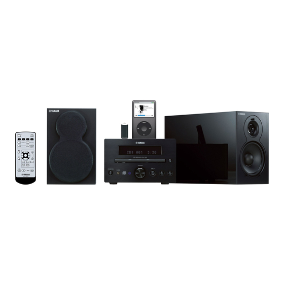
The MCR-230 consists of the CRX-330 and NS-BP100.
This manual has been provided for the use of authorized YAMAHA Retailers and their service personnel.
It has been assumed that basic service procedures inherent to the industry, and more specifi cally YAMAHA Products, are already known
and understood by the users, and have therefore not been restated.
WARNING:
IMPORTANT:
The data provided is believed to be accurate and applicable to the unit(s) indicated on the cover. The research, engineering, and service
departments of YAMAHA are continually striving to improve YAMAHA products. Modifications are, therefore, inevitable and
specifi cations are subject to change without notice or obligation to retrofi t. Should any discrepancy appear to exist, please contact the
distributor's Service Division.
WARNING:
IMPORTANT:
■ CONTENTS
TO SERVICE PERSONNEL ........................................2-4
SYSTEM COMPOSITION ................................................6
FRONT PANELS .............................................................7
REAR PANELS ...............................................................8
REMOTE CONTROL PANEL ..........................................9
SPECIFICATIONS ................................................... 10-11
INTERNAL VIEW .......................................................... 12
DISASSEMBLY PROCEDURES ............................. 13-15
UPDATING FIRMWARE .......................................... 16-19
1 0 1 1 3 7
MICRO COMPONENT SYSTEM
CD RECEIVER /
For B model
IMPORTANT NOTICE
Failure to follow appropriate service and safety procedures when servicing this product may result in personal injury,
destruction of expensive components, and failure of the product to perform as specifi ed. For these reasons, we advise
all YAMAHA product owners that any service required should be performed by an authorized YAMAHA Retailer or
the appointed service representative.
The presentation or sale of this manual to any individual or fi rm does not constitute authorization, certifi cation or
recognition of any applicable technical capabilities, or establish a principle-agent relationship of any form.
Static discharges can destroy expensive components. Discharge any static electricity your body may have
accumulated by grounding yourself to the ground buss in the unit (heavy gauge black wires connect to this buss).
Turn the unit OFF during disassembly and part replacement. Recheck all work before you apply power to the unit.
SELF-DIAGNOSTIC FUNCTION ............................20-32
DISPLAY DATA .............................................................33
IC DATA ...................................................................34-40
PIN CONNECTION DIAGRAMS .............................41-42
BLOCK DIAGRAM ........................................................43
PRINTED CIRCUIT BOARDS .................................44-50
SCHEMATIC DIAGRAMS .......................................51-56
REPLACEMENT PARTS LIST ................................57-66
REMOTE CONTROL ...............................................67-68
Copyright © 2009
This manual is copyrighted by YAMAHA and may not be copied or
redistributed either in print or electronically without permission.
NS-BP100
SERVICE MANUAL
All rights reserved.
MCR-230
SPEAKERS
P.O.Box 1, Hamamatsu, Japan
animate '09.06
Table of Contents

Related Manuals for Yamaha MCR-330


Summary of Contents for Yamaha MCR-330
-
Page 1: Table Of Contents
This manual has been provided for the use of authorized YAMAHA Retailers and their service personnel. It has been assumed that basic service procedures inherent to the industry, and more specifi cally YAMAHA Products, are already known and understood by the users, and have therefore not been restated. -
Page 2: To Service Personnel
CRX-330/NS-BP100 ■ TO SERVICE PERSONNEL AC LEAKAGE 1. Critical Components Information WALL EQUIPMENT TESTER OR Components having special characteristics are marked OUTLET UNDER TEST EQUIVALENT must be replaced with parts having specifications equal to those originally installed. 2. Leakage Current Measurement (For 120V Models Only) When service has been completed, it is imperative to verify INSULATING that all exposed conductive surfaces are properly insulated... - Page 3 CRX-330/NS-BP100 WARNING: Lithium batteries CAUTION Danger of explosion if battery is incorrectly replaced. Replace only with the same or equivalent type. WARNING: ADVARSEL! Lithium batteries are dangerous because they can be exploded by improper handling. Observe the Lithiumbatteri –Eksplosionsfare ved fejlagtig håndtering. following precautions when handling or replacing lithium Udskiftning må...
- Page 4 CRX-330/NS-BP100 Warning for power supply The primary side of the power supply carries live mains voltage when the player is connected to the mains even when the player is switched off ! This primary area is not shielded so it is possible to accidentally touch copper tracks and/or components when servicing the player.
-
Page 5: Prevention Of Electrostatic Discharge
CRX-330/NS-BP100 ■ PREVENTION OF ELECTROSTATIC DISCHARGE Some semiconductor (solid state) devices can be damaged easily by static electricity. Such components commonly are called Electrostatically Sensitive (ES) Devices. Examples of typical ES devices are integrated circuits and some field-effect transistors and semiconductor “chip” components. The following techniques should be used to help reduce the incidence of component damage caused by electro static discharge (ESD). -
Page 6: System Composition
CRX-330/NS-BP100 ■ SYSTEM COMPOSITION The MCR-230 consists of the CRX-330 and NS-BP100. MCR-230 ▼ NS-BP100 ▼ NS-BP100 ▼ CRX-330... -
Page 7: Front Panels
CRX-330/NS-BP100 ■ FRONT PANELS CRX-330 Top view Front view NS-BP100... -
Page 8: Rear Panels
CRX-330/NS-BP100 ■ REAR PANELS CRX-330 NS-BP100... -
Page 9: Remote Control Panel
CRX-330/NS-BP100 ■ REMOTE CONTROL PANEL... -
Page 10: Specifications
CRX-330/NS-BP100 ■ SPECIFICATIONS CRX-330 NS-BP100 ■ Audio Section ■ Audio Section Minimum RMS Output Power (Power Amp. Section) Type ..........2-way bass reflex speaker system (L/R drive, 1 kHz, 10 % THD, 6 ohms) ......20 W + 20 W Non-magnetic shielding type Rated Output Voltage/Output Impedance Driver SUBWOOFER ............ - Page 11 CRX-330/NS-BP100 • DIMENSIONS CRX-330 NS-BP100 Top view Top view 152 (5-15/16") Front view Front view 180 (7-1/8") 123 (4-7/8") Unit: mm (inch)
-
Page 12: Internal View
CRX-330/NS-BP100 ■ INTERNAL VIEW CRX-330 POWER (1) P.C.B. Top view DAB MODULE DAB P.C.B. MAIN (1) P.C.B. MAIN (2) P.C.B. POWER (2) P.C.B. LOADER MECHANISM UNIT Front view... -
Page 13: Disassembly Procedures
CRX-330/NS-BP100 ■ DISASSEMBLY PROCEDURES CRX-330 (Remove parts in the order as numbered.) Disconnect the power cable from the AC outlet. 1. Removal of Top Cover Ass’y ➀ ➁ Remove 4 screws ( ) and 4 screws ( ). (Fig. 1) b. - Page 14 CRX-330/NS-BP100 3. Removal of Loader Mechanism Unit and POWER (1) P.C.B. ➅ Remove 5 screws ( ). (Fig. 2) b. Lift the POWER (1) P.C.B. and POWER support together. (Fig. 2) ➆ Remove 4 screws ( ). (Fig. 2) d. Lift the loader mechanism unit. (Fig. 2) Remove CB212 and CB213.
- Page 15 CRX-330/NS-BP100 When checking the P.C.B.s: • Spread the rubber sheet and the cloth. Then place this unit on the cloth and check it. (Fig. 3) • Reconnect all cables (connectors) that have been disconnected. • When connecting the flexible flat cable, be careful with polarity. •...
-
Page 16: Updating Firmware
CRX-330/NS-BP100 ■ UPDATING FIRMWARE When replacing the following parts with the replacement parts, be sure to write the latest firmware. MAIN P.C.B. Microprocessor (IC211) of MAIN P.C.B. ● Required tools ● Confirmation of firmware version and checksum Before and after updating the firmware, check the •... -
Page 17: Operation Procedures
CRX-330/NS-BP100 ● Operation procedures 1. Connect the power cable of this unit to the AC outlet. 2. Start up FlashSta.exe. (Fig. 2) The screen appears as shown below. (Fig. 2) 3. Select the data to be transmitted and port. (Fig. 2) •... - Page 18 CRX-330/NS-BP100 5. Click [Setting], and set the baud rate. (Fig. 4) Select 115200 bps for the baud rate and 40 ms for the program intervals. Reduce the baud rate if a transmission error occurs frequently. Fig. 4 6. Click [E.P.R.], then the Erase screen appears.
- Page 19 CRX-330/NS-BP100 8. When writing of the firmware is completed, the screen appears as shown below. (Fig. 6) Click [OK]. (Fig. 6) 9. Click [Exit] to end FlashSta.exe. (Fig. 6) Fig. 6 Start up the self-diagnostic function of this unit and select the “1. FIRMWARE VERSION” menu. 10.
-
Page 20: Self-Diagnostic Function
CRX-330/NS-BP100 ■ SELF-DIAGNOSTIC FUNCTION There are 11 main menu items, each of which has sub-menu items. Listed in the table below are main menu items and sub-menu items. MAIN MENU SUB MENU 1 ROM VER/SUM 1 MAIN VERSION 2 MAIN CHECKSUM 3 CD VERSION 4 USB VERSION 5 DAB VERSION... - Page 21 CRX-330/NS-BP100 ● Starting Self-Diagnostic Function While pressing those 2 keys of this unit as shown in the figure below, press the “STANDBY/ON” key to turn on the power. The self-diagnostic function mode is activated. Keys of this unit While pressing these keys, turn on the power. Display ●...
- Page 22 CRX-330/NS-BP100 ● Display provided when Self-Diagnostic Function started The FL display of this unit displays the protection function history data then the main menu (sub-menu MAIN CPU VERSION of main menu 1. ROM VER/SUM) a few seconds later. When there is no history of protection function: Opening message Main menu display After a few seconds...
- Page 23 CRX-330/NS-BP100 ● Operation procedure of Main menu and Sub-menu There are 11 main menu items, each of them having sub-menu items. Main menu selection Select the main menu using “ ” (Forward) and “ ” (Reverse) keys on the remote control. Sub-menu selection Select the sub-menu using “ENTER”...
- Page 24 CRX-330/NS-BP100 ● Details of Self-Diagnostic Function menu 1. ROM VER/SUM The firmware version and checksum are displayed. The checksum is obtained by adding the data at every 8 bits for each program area and expressing the result as a 4-figure hexadecimal data.
- Page 25 CRX-330/NS-BP100 2. AUDIO TEST Using the sub-menu, the input source is changed as shown below. 2-1 iPod™ iPod is selected. 2-2 TUNER TUNER is selected. (Initial value: 98.1MHz) 2-3 CD CD is selected. 2-4 USB Reproduced at this time is the first piece of the music file in the USB flash memory connected to the USB terminal of this unit.
- Page 26 CRX-330/NS-BP100 3. FL CHECK This menu is used to check the FL display section. Using the sub-menu, the display varies as shown below. 3-1 Initial display Initial display 3-2 All segments OFF All segments OFF 3-3 All segments ON (dimmer 100%) All segments ON (dimmer 100%) 3-4 All segments ON (dimmer 50%) All segments ON (dimmer 50%)
- Page 27 CRX-330/NS-BP100 4. iPod ™ Not applied to this model. 5. MAIN PCB CHECK Communication and bus line connection between devices on the MAIN P.C.B. are checked. 5-1 ALL Check OK : No error detected NG : An error is detected 5-2 I2C Check The I2C bus line connection is checked.
- Page 28 CRX-330/NS-BP100 6. CD CHECK This menu is used to check operation of the loader mechanism unit. Select sub-menu and press the “PLAY/PAUSE” key on the remote control to change operation mode. 6-1 Laser Diode Check ON / OFF 6-2 Spindle Motor Check FREE (OFF) / ACC (ON) 6-3 Feed Motor Check --- (OFF) / OUT (Outside) / --- (OFF) / IN (Inside)
- Page 29 CRX-330/NS-BP100 SYSTEM MONITOR This menu is used to display the A/D conversion value of the main microprocessor which detects panel keys of this unit and protection functions by using the sub-menu. 7-1 PS1 / PS2 (Power supply voltage protection detection) Power supply voltage protection value (Normal value: PS1: 103 to 168, PS2: 101 to 151) PS1: Detects +3.3D, +5A, +5I, +12A, +15AMP, -23D and -32D.
- Page 30 CRX-330/NS-BP100 7-5 DESTINATION (Destination detection) The voltage at 94 pin of microprocessor (IC211) is displayed with 3.3V/255 as a reference. Display 194 – 233 Destination 7-6 KEY0 / KEY1 / KEY2 (Panel key of this unit detection) The voltage at 97 pin (KEY0), 95 pin (KEY1) and 70 pin (KEY2) of microprocessor IC211 are displayed with 3.3V/255 as a reference.
- Page 31 CRX-330/NS-BP100 8. PROTECTION HISTORY The history of protection function is displayed. Select sub-menu and press the “PLAY/PAUSE” key on the remote control, then the history will be erased. 8-1 Last 8-2 History 1 8-3 History 2 8-4 History 3 9. SET INFORMATION The model name and destination are displayed.
- Page 32 CRX-330/NS-BP100 A. SOFT SWITCH Not applied to this model. B. FACTORY PRESET This menu is used to reserve/inhibit initialization of the back-up IC (tuner preset, etc...). B-1 PRESET INH (Initialization inhibited) IC initialization is not executed. Select this sub-menu to protect the values set by the user. B-2 PRESET RSRV (Initialization reserved) Initialization of the back-up IC is reserved.
-
Page 33: Display Data
CRX-330/NS-BP100 ■ DISPLAY DATA ● V801 : 16-BT-133GNK (POWER P.C.B.) PATTERN AREA ● PIN CONNECTION Pin No. Connection Pin No. Connection Note : 1) F1, F2 ..Filament 2) NP ..No pin 3) NX ..No extended Pin 4) 1G–16G ..Grid 5) NC .. -
Page 34: Ic Data
CRX-330/NS-BP100 ■ IC DATA IC211: R5F3640DNFA (MAIN P.C.B.) Single-chip 16-bit CMOS microprocessor Port P0 Port P1 Port P2 Port P3 Port P4 Port P5 VCC2 ports Internal peripheral functions UART or clock synchronous Clock generation circuit serial I/O Timer (16-bit) (6-channels) COUT PLL frequency synthesizer... - Page 35 CRX-330/NS-BP100 Function Name Port Name Detail of Function (P.C.B.) P96/ANEX1/SOUT4 RDS_N_RST P95/ANEX0/CLK4 RDS_SCK P94/DA1/TB4in RDS_RDY P93/DA0/TB3in TUN_N_CS For FL control / TUNER control P92/TB2in/SOUT3 FL_MOSI 3.3V to 5.0V conversion for TUNER For TUNER control P91/TB1in/SIN3 TUN_MISO 5.0V to 3.3V conversion For FL control / TUNER control P90/TB0in/CLK3 FL_SCK...
- Page 36 CRX-330/NS-BP100 Function Name Port Name Detail of Function (P.C.B.) Reset for iPod certified chip 45 P51/WRH/BHE ICP_N_RST 47k pull-down 46 P50/WRL/WR iPod certified chip/DSP communication I2C 47 P47/CS3/TXD7/SDA7 DSP_SDA +3.3V/3.3k-ohms pull-up iPod certified chip/DSP communication I2C 48 P46/CS2/RXD7/SCL7 DSP_SCL +3.3V/3.3k-ohms pull-up 49 P45/CS1/CLK7 CD_OPEN CD tray OPEN control...
- Page 37 CRX-330/NS-BP100 Function Name Port Name Detail of Function (P.C.B.) iPod charging power ON/OFF control 88 P00/D0/AN00 IPD_PON Hi = ON / 47k pull-down iPod audio signal detection 89 P107/AN7/KI3 IPAU_DET Whether audio signal from iPod present or not judged with AD value 90 P106/AN6/KI2 PS2_PRT...
- Page 38 CRX-330/NS-BP100 IC218: MN103SFB5KYAA (MAIN P.C.B.) USB microprocessor INTERFACE 32 bit MEMORY 256 KByte 8 KB FLASH MICRO- DMA 4 CH MEMORY PROCESSOR CORE DATA 8 KByte I/O port INTERRUPT TIMER 34 pcs (3 V type) 8 pcs (5 V type) CONTROL 8-bit x 4 WDTx1...
- Page 39 CRX-330/NS-BP100 Port Name Function Name Detail of Function N.C. USBNOC USB over-current input (negative polarity) USBNPP USB, VBUS power output control terminal (negative polarity) USBD- USB D- terminal AVSS Ground / Analog power supply for USB / Connect to VSS. USBD+ USB D+ terminal AVDD...
- Page 40 CRX-330/NS-BP100 Port Name Function Name Detail of Function 50 N.C. N.C. 53 VSS Ground 54 STREQ PD5/IRQ2 External interrupt request signal input terminal 55 CS PD4/IRQ1 External interrupt request signal input terminal 56 N.C. 57 TX PD1/SBI2 Clock synchronization/start stop synchronization serial terminal 58 RX PD0/SBO2 Clock synchronization/start stop synchronization serial terminal...
-
Page 41: Pin Connection Diagrams
CRX-330/NS-BP100 ■ PIN CONNECTION DIAGRAMS • ICs AN41010A-VF BD9302FP-E2 BD9870FPS-E2 L6566BTR R2A15908SP M12L16161A-7TG M24C02-RDW6TP M66003-0131FP-R MN103SFB5KYAA MN6627971YB NJM2737M NJM431U NJM4580E NJM7812FA NJM4580V-TE2 1: REFERENCE 2: ANODE 3: IN 3: CATHODE 1: OUT 2: COM R1154H001C-T1-F R3112N251A-TR R5523N001A-TR-F R5F3640DNFA YDA146-SZE2 PQ012GN01ZPH TC7WH125FK 1: Vin 2: VB... - Page 42 CRX-330/NS-BP100 • Diodes 1SR154-400 1SS355 D1NL20U-5083 D3S6M-7002 D1FK60-5063 D1FL20U-5063 Anode Anode Anode ANODE Cathode Cathode Cathode CATHODE D5SBA60 P6KE200ARL MA8051-M 5.1V MAZ8100GOL 10.0V MA8056-L 5.4V MAZ8056GLL 5.4V MA8068-M 6.8V MAZ8140GML 14V Anode MA8160-L 15.7V MAZ8051GLL 5.0V Anode MA8220-M 22.0V MAZ8240GML 24.0V MAZ8033GOL 3.3V –...
-
Page 43: Block Diagram
CRX-330/NS-BP100 ■ BLOCK DIAGRAM iPod VOLUME +3.3S 35mA FL/Driver -23V 30mA PHONES V801/IC801 KEY0 KEY1 MAIN -23V POWER STANDBY/ON → +3.3M → +3.3S SCHEMATIC DIAGRAM +15D_FL SCHEMATIC DIAGRAM +12RY +3.3M SUB- S_6V Transformer +3.3S IC222 IC212 Writing port IC208 EEPROM +3.3M AC IN -23V... -
Page 44: Printed Circuit Boards
CRX-330/NS-BP100 MAIN (2) (CB703) ■ PRINTED CIRCUIT BOARDS POWER (1) POINT A XL202 (Pin 15 of IC211) POWER (1) (W2) MAIN (2) (W4) (CB704) MAIN (1) P.C.B. (Side A) • Semiconductor Location No replacement part available. POWER (1) Ref No. Location (W1) D203 D204... - Page 45 CRX-330/NS-BP100 MAIN (1) P.C.B. (Side B) • Semiconductor Location Ref No. Location D206 IC222 Q211 Q214 Q217 Q218 Q219 Q222 Q223 Q224 Q228 Q229...
- Page 46 CRX-330/NS-BP100 MAIN (2) P.C.B. MAIN (2) P.C.B. (Side A) (Side B) • Semiconductor Location Ref No. Location D703 D704 IC701 USB_GND USB_GND DGND IPAU_DET IGND IGND IC701 MAIN (1) (W201) iPod No replacement part available. IPD_DET ACC_DET IPD_MISO IPD_MOSI IPAP_DET AGND REM_SENSE AGND...
- Page 47 CRX-330/NS-BP100 AMPGND POWER (1) P.C.B. POWER (1) P.C.B. (Side A) (Side B) AMPGND MAIN (1) AMPVCC (CB205) AMPVCC MAIN (1) • Semiconductor Location (CB216) Ref No. Location IC11 AGND MAIN (2) +12A (CB210) +3.3D S_6V PRY_CTRL PS1_PRT PWR_DET -32V MAIN (1) (CB206) IGND MAIN (1)
- Page 48 CRX-330/NS-BP100 POWER (2) P.C.B. (Side A) • Semiconductor Location Ref No. Location Q802 Q803 VOL_RB VOL_RA Q804 KEY1 KEY0 DGND2 REMOTE DGND1 +3.3M FL_SCK FL_MOSI FL_N_CS FL_N_RST DGND1 +3.3S +15V_FL FL_CLOCK MAIN (1) (CB208) INPUT STANDBY/ON VOLUME PHONES W801 TO CHASSIS HP_R AGND HP_L...
- Page 49 CRX-330/NS-BP100 POWER (2) P.C.B. (Side B) • Semiconductor Location Ref No. Location D801 D802 D803 D804 D805 D807 D809 D810 D811 D812 D813 IC801 Q801 Q805 Q806...
- Page 50 CRX-330/NS-BP100 DAB P.C.B. DAB P.C.B. (Side A) (Side B) DAB MODULE IC901 CB901 DAB_R AGND DAB_L DRD_N_RST • Semiconductor Location DAB_SD DAB_BCK Ref No. Location DAB_WCK IC901 DAB_MCK/SPDIF DAB_SCL +3.3D DAB_SDA MAIN (CB202)
-
Page 51: Schematic Diagrams
CRX-330/NS-BP100 SCHEMATIC DIAGRAMS MAIN 1/3 MAIN (1) W201 SW OUT 12.0 Page 53 SUBWOOFER OUT IC209 IC209 to MAIN (2)_CB703 -26.6 -27.0 IC223 Page 53 W202 to MAIN (2)_CB704 12.0 IC205 IC223 CB207 Page 55 to POWER (2)_W802 No replacement part available. 12.0 IC205 OUT L... - Page 52 CRX-330/NS-BP100 MAIN 2/3 CB216 MAIN (1) Page 54 to POWER (1)_W1 IC219 15.3 15.3 CD CONTROLLER IC217 IC221 CD IN CB211 USB CURRENT LIMIT IC IC220 USB CONTROLLER POINT C XL203 (Pin 109 of IC217) CB212 to Loader mechanism unit CD IN CB213 POINT D XL204 (Pin 11 of IC218)
- Page 53 CRX-330/NS-BP100 MAIN 3/3 CB703 MAIN (2) Page 51 to MAIN (1)_W201 CB704 IPOD IN Page 51 to MAIN (1)_W202 IC701 IC701 IC701: NJM4580V-TE2 Dual operational amplifier 2, 6 1, 7 OUTPUT –INPUT +INPUT 3, 5 V– ★ All voltages are measured with a 10MΩ/V DC electronic voltmeter. ★...
- Page 54 CRX-330/NS-BP100 POWER 1/2 IC11 Page 52 to MAIN (1)_CB216 15.3 Page 51 to MAIN (1)_CB205 12.1 (133.3) Page 51 to MAIN (1)_CB206 (318.9) (319.2) (133.5) (317.8) (454.7) (454.6) 13.1 (318.5) (3.1) 16.8 12.0 (318.5) 12.1 AC IN IC13 12.0 16.8 (0.8) 16.8 12.8...
- Page 55 CRX-330/NS-BP100 POWER 2/2 15.3 15.3 12.8 12.8 13.2 -17.0 -16.5 -14.9 -21.0 -15.0 -13.3 -17.9 -21.0 13.2 -21.0 -10.3 -20.9 -11.8 -10.4 -15.0 -19.6 -22.7 -19.6 IC801 -19.4 -21.0 -12.1 -11.9 -10.4 -22.5 FL DRIVER -21.0 -21.0 -20.7 CB801 Page 51 to MAIN (1)_CB208 W802 Page 51...
- Page 56 CRX-330/NS-BP100 IC901: PQ012GN01ZPH Low power loss regulator DC input DC output (Vin) (Vo) Bias power supply (VB) IC901 CB901 CB902 To DAB MODULE Page 51 to MAIN (1)_CB202 ★ All voltages are measured with a 10MΩ/V DC electronic voltmeter. ★ Components having special characteristics are marked and must be replaced with parts having specifications equal to those originally installed.
-
Page 57: Replacement Parts List
CRX-330/NS-BP100 ■ REPLACEMENT PARTS LIST • ELECTRICAL COMPONENT PARTS WARNING ● Components having special characteristics are marked and must be replaced with parts having specifications equal to those originally installed. ABBREVIATIONS IN THIS LIST ARE AS FOLLOWS: C.A.EL.CHP : CHIP ALUMI.ELECTROLYTIC CAP L.EMIT : LIGHT EMITTING MODULE C.CE... - Page 58 CRX-330/NS-BP100 P.C.B. MAIN Ref No. Part No. Description Markets Ref No. Part No. Description Markets WQ542400 P.C.B. MAIN C290-291 US135100 C.CE.CHP 0.1uF CB202 VM859600 CN.BS.PIN C292-293 US061330 C.CE.CHP 33pF 50V B CB203 VQ044400 CN.BS.PIN C294 US135100 C.CE.CHP 0.1uF CB205 LB918040 CN.BS.PIN C295 US062100 C.CE.CHP 100pF...
- Page 59 CRX-330/NS-BP100 P.C.B. MAIN Ref No. Part No. Description Markets Ref No. Part No. Description Markets C384 US135100 C.CE.CHP 0.1uF C462 US135100 C.CE.CHP 0.1uF C385 US063560 C.CE.CHP 5600pF 50V B C463 WP882000 C.CE.CHP 10uF 6.3V C386 US065100 C.CE.CHP 0.1uF 50V B C464 US135100 C.CE.CHP 0.1uF...
- Page 60 CRX-330/NS-BP100 P.C.B. MAIN and P.C.B. POWER Ref No. Part No. Description Markets Ref No. Part No. Description Markets C549 US063560 C.CE.CHP 5600pF 50V B IC207 YA679A00 IC NJM2737M OPAMP C550 US163100 C.CE.CHP 1000pF IC208 X9056A00 IC M24C02-RDW6TP C551-553 US135100 C.CE.CHP 0.1uF IC209 X2331A00 IC...
- Page 61 CRX-330/NS-BP100 P.C.B. POWER Ref No. Part No. Description Markets Ref No. Part No. Description Markets C7-8 WJ322300 C.CE.M.CHP 1000pF 630V C803-804 US163100 C.CE.CHP 1000pF US063220 C.CE.CHP 2200pF 50V B C805 UF437100 C.EL.CHP 10uF WD969200 C.CE.CHP 0.1uF 50V K C806-807 US135100 C.CE.CHP 0.1uF UB214820 C.CE.M.CHP 0.082uF C808...
- Page 62 CRX-330/NS-BP100 P.C.B. POWER and P.C.B. DAB Ref No. Part No. Description Markets Ref No. Part No. Description Markets VV556500 TR 2SA1037K Q,R,S Q801 VV556400 TR 2SC2412K Q,R,S Q802 VP872700 TR 2SC4488 S,T Q803 VP872600 TR 2SA1708 S,T Q804 VP872700 TR 2SC4488 S,T Q805 VV556400 TR...
- Page 63 CRX-330/NS-BP100 Carbon Resistors Value 1/4W Type Part No. 1/6W Type Part No. Value 1/4W Type Part No. 1/6W Type Part No. 1.0 Ω HJ35 3100 HF85 3100 11 kΩ HF45 7110 HF45 7110 ✻ 1.8 Ω 3180 12 kΩ 7120 7120 HJ35 HJ35...
- Page 64 CRX-330/NS-BP100 CRX-330 3-111 • OVERALL ASS'Y 2-102 2-101 2-103 2-110 2-104 1-115 5 (2) 2-111 1-106 2-111 1-101 1-115 5 (1) 1-107 1-105 1-109 1-108 1-107 1-102 1-104 300-1 iPod...
- Page 65 CRX-330/NS-BP100 Ref No. Part No. Description Remarks Markets Ref No. Part No. Description Remarks Markets * 1-101 WR562500 FRONT PANEL WE975300 PW HEAD B-TIGHT SCREW MFZN2B3 * 1-101 WR562300 FRONT PANEL VY712800 PW HEAD B-TIGHT SCREW 3x8-8 MFNI33 1-102 WP231100 SUB PANEL WQ726200 RADIATION SHEET...
- Page 66 CRX-330/NS-BP100 NS-BP100 • OVERALL ASS’Y Ref No. Part No. Description Remarks Markets WQ169000 CABINET ASS'Y WQ168900 CABINET ASS'Y WQ099300 FRONT GRILLE ASS'Y Black color * 2-3 WP938000 HOLDER WP937700 FRONT PANEL Black color YA111A00 DRIVER WOOFER 10cm 4Ω JA10B1 YA112A00 DRIVER TWEETER 2.5cm 6Ω...
-
Page 67: Remote Control
CRX-330/NS-BP100 ■ REMOTE CONTROL SCHEMATIC DIAGRAM JP1 to JP6: Not mounted 1 ohm, 1/4W MIE-554A2 47μF 27 ohms, 1/10W 2SC3440-T112 CARR IC1: M34283G2GP-U1/W5 Z-N0102-87055 #1X XOUT 3.0V 0.1μF KEY No. 4.00MHz PANEL... - Page 68 CRX-330/NS-BP100 KEY LAYOUT KEY CODE Custom Data Key Name code code STANDBY/ON SLEEP iPod DAB/FM PRESET < PRESET > TUNING << TUNING >> MEMORY FUNCTION DISPLAY FOLDER FOLDER (stop) SHUFFLE REPEAT MUTE VOLUME (down) VOLUME (up) MENU (skip-/reverse) (play/pause) (skip+/forward) (CENTER)
- Page 69 CRX-330/NS-BP100 MEMO...
- Page 70 CRX-330/ NS-BP100...