ZyXEL Communications IES-1248 VDSL-SWITCH User Manual
Adsl2+ ip dslam
Hide thumbs
Also See for IES-1248 VDSL-SWITCH:
- Support notes (92 pages) ,
- Specifications (2 pages) ,
- Specifications (6 pages)
Table of Contents
Quick Links
Table of Contents
Troubleshooting

Related Manuals for ZyXEL Communications IES-1248 VDSL-SWITCH


Summary of Contents for ZyXEL Communications IES-1248 VDSL-SWITCH
- Page 1 IES-1248 ADSL2+ IP DSLAM User’s Guide 5/2005 Version 3.50(LS.0), (TR.0)
- Page 2 Published by ZyXEL Communications Corporation. All rights reserved. Disclaimer ZyXEL does not assume any liability arising out of the application or use of any products, or software described herein. Neither does it convey any license under its patent rights nor the patents rights of others. ZyXEL further reserves the right to make changes in any products described herein without notice.
-
Page 3: Interference Statements And Warnings
This is a class A product. In a domestic environment this product may cause radio interference in which case the user may be required to take adequate measures. Taiwanese BSMI (Bureau of Standards, Metrology and Inspection) A Warning: Certifications Refer to the product page at www.zyxel.com. Interference Statements and Warnings... -
Page 4: Safety Warnings
IES-1248 User’s Guide Safety Warnings For your safety, be sure to read and follow all warning notices and instructions. Refer to the Hardware Specifications appendix for the gauge of wire to use for each connection. With the AC power model, connect the power cord to the right supply voltage (110V AC in North America or 230V AC in Europe). -
Page 5: Zyxel Limited Warranty
Any replacement will consist of a new or re-manufactured functionally equivalent product of equal value, and will be solely at the discretion of ZyXEL. This warranty shall not apply if the product is modified, misused, tampered with, damaged by an act of God, or subjected to abnormal working conditions. -
Page 6: Customer Support
IES-1248 User’s Guide Customer Support If you have questions about your ZyXEL product or desire assistance, contact ZyXEL Communications Corporation offices worldwide, in one of the following ways: Contacting Customer Support When you contact your customer support representative, have the following information ready: ♦... - Page 7 WEB SITE REGULAR MAIL SALES E-MAIL FTP SITE LOCATION SWEDEN [email protected] +46 31 744 7700 www.zyxel.se ZyXEL Communications A/S Sjöporten 4, 41764 Göteborg [email protected] +46 31 744 7701 Sweden UNITED KINGDOM [email protected] +44 (0) 8702 909090 www.zyxel.co.uk ZyXEL Communications UK Ltd.,11 The Courtyard,...
-
Page 8: Table Of Contents
IES-1248 User’s Guide Table of Contents Copyright ..................................ii Interference Statements and Warnings........................iii Safety Warnings ................................iv ZyXEL Limited Warranty............................... v Customer Support ................................vi List of Figures ................................xv List of Tables ................................xx Preface ..................................xxiii Chapter 1 Getting to know the IES-1248....................... 1-1 Integrated Ethernet Switch Overview .................... - Page 9 IES-1248 User’s Guide MDF Connections Overview........................4-1 MDF (Main Distribution Frame) ......................4-1 Telco-50 Cables ............................ 4-2 Telco-50 Connections ........................... 4-2 MDF Scenarios............................4-2 Typical MDF Scenarios ......................... 4-3 Chapter 5 Power Connections ..........................5-1 Power Connections Overview ....................... 5-1 Power Connections ..........................
- Page 10 IES-1248 User’s Guide 10.7 IP Setup ............................. 10-11 10.8 ENET Port Setup ..........................10-12 Chapter 11 ADSL Port Setup ..........................11-1 11.1 ADSL Standards Overview........................11-1 11.2 Downstream and Upstream......................... 11-1 11.3 Profiles..............................11-1 11.4 Interleave Delay........................... 11-2 11.5 Configured Versus Actual Rate ......................11-2 11.6 Default Settings ...........................
- Page 11 IES-1248 User’s Guide 16.2 MAC Filter Configuration ........................16-1 Chapter 17 Spanning Tree Protocol ........................17-3 17.1 RSTP (Rapid Spanning Tree Protocol) and STP (Spanning Tree Protocol) ........17-3 17.2 STP Status ............................17-5 Chapter 18 Port Authentication ........................... 18-1 18.1 Introduction to Authentication......................
- Page 12 IES-1248 User’s Guide 24.7 Command Line FTP..........................24-3 Chapter 25 Diagnostic ............................ 25-1 25.1 Diagnostic ............................25-1 25.2 Log Format ............................25-2 25.3 Line Diagnostics Test Parameters....................... 25-4 Chapter 26 MAC Table ........................... 26-1 26.1 Introduction to MAC Table........................26-1 26.2 Viewing the MAC Table ........................
- Page 13 IES-1248 User’s Guide 32.3 MAC Count Commands ........................32-3 Chapter 33 IGMP Filter Commands ........................33-1 33.1 IGMP Filter Commands........................33-1 Chapter 34 Packet Filter Commands ........................34-1 34.1 Packet Filter Commands ........................34-1 Chapter 35 IP Commands........................... 35-1 35.1 IP Commands Introduction........................
- Page 14 IES-1248 User’s Guide 40.4 1000/100 LEDs Do Not Turn On ......................40-2 40.5 1000/100 Ethernet Port Data Transmission ..................40-2 40.6 DSL Data Transmission........................40-3 40.7 There Is No Voice on an ADSL Connection ..................40-3 40.8 Testing Wiring............................40-3 40.9 Local Server............................
-
Page 15: List Of Figures
IES-1248 User’s Guide List of Figures Figure 1-1 MTU Application............................1-5 Figure 1-2 Curbside Application ..........................1-5 Figure 2-1 Attaching Rubber Feet ..........................2-2 Figure 2-2 Attaching Mounting Brackets and Screws ....................2-3 Figure 2-3 Rack Mounting ............................2-3 Figure 2-4 IES-1248 Frame Ground ......................... 2-4 Figure 3-1 Front Panel (AC Power Version)...................... - Page 16 IES-1248 User’s Guide Figure 8-3 IP Setup..............................8-2 Figure 8-4 Basic Setting xDSL Port Setup Menu ...................... 8-3 Figure 8-5 xDSL Port Setup ............................8-3 Figure 8-6 Deleting a PVC............................8-3 Figure 8-7 Select Ports.............................. 8-4 Figure 8-8 Adding a New Channel..........................8-4 Figure 8-9 Copying the PVC............................
- Page 17 IES-1248 User’s Guide Figure 11-13 IGMP Filter Profile..........................11-21 Figure 11-14 Line Rate Information........................11-23 Figure 11-15 Line Performance..........................11-25 Figure 11-16 Line Data ............................11-27 Figure 12-1 VLAN Status............................12-3 Figure 12-2 Static VLAN Setting..........................12-5 Figure 12-3 VLAN Port Setting..........................12-7 Figure 12-4 Select Ports............................
- Page 18 IES-1248 User’s Guide Figure 24-2 Firmware Upgrade ..........................24-1 Figure 24-3 Restore Configuration .......................... 24-2 Figure 24-4 Confirm Restore Factory Default Settings ................... 24-3 Figure 24-5 Restart After Load Factory Defaults ..................... 24-3 Figure 24-6 Confirm Restart ............................ 24-3 Figure 25-1 Diagnostic ............................25-1 Figure 26-1 MAC Table Filtering Flowchart ......................
- Page 19 IES-1248 User’s Guide Figure 35-1 IP Settings and Default Gateway Address................... 35-2 Figure 35-2 Route Show Command Example......................35-3 Figure 35-3 ARP Show Command Example ......................35-4 Figure 35-4 Statistics IP Command Example......................35-4 Figure 36-1 Configuration File Example........................36-3 Figure 38-1 ADSL Show Command Example ......................
- Page 20 IES-1248 User’s Guide List of Tables Table 3-1 IES-1248 Front Panel Ports........................3-1 Table 3-2 LED Descriptions ............................3-2 Table 7-1 Navigation Panel Sub-links Overview......................7-3 Table 7-2 Web Configurator Screens ........................7-3 Table 8-1 Default Settings ............................8-6 Table 9-1 Home ................................. 9-2 Table 9-2 Ethernet Port Statistics ..........................
- Page 21 Table 22-2 SNMP Commands..........................22-2 Table 22-3 RFC-1215 SNMP Traps......................... 22-3 Table 22-4 ADSL Line SNMP Traps ........................22-3 Table 22-5 ZyXEL Private MIB SNMP Traps......................22-4 Table 22-6 Access Control: SNMP .......................... 22-5 Table 22-7 Access Control: Logins.......................... 22-6 Table 22-8 Access Control: Service Access Control ....................
- Page 22 IES-1248 User’s Guide Table 40-2 ALM LED Troubleshooting........................40-1 Table 40-3 SFP LNK LED Troubleshooting ......................40-2 Table 40-4 1000/100 LED Troubleshooting ......................40-2 Table 40-5 Ethernet Port Data Transmission Troubleshooting................40-2 Table 40-6 DSL Data Transmission Troubleshooting ....................40-3 Table 40-7 ADSL Voice Troubleshooting .........................
-
Page 23: Preface
Web Configurator Online Help Embedded web help for descriptions of individual screens and supplementary information. Glossary and ZyXEL Web Site Please refer to www.zyxel.com for an online glossary of networking terms or the ZyXEL download library for additional support documentation. Preface... - Page 24 IES-1248 User’s Guide Firmware Naming Conventions A firmware version includes the model code and release number as shown in the following example. Firmware Version: V3.50(LS.0) “LS” is the model code. “LS” denotes the IES-1248-71 for ADSL over POTS (Annex A). “TR”...
- Page 25 IES-1248 Overview Part I: IES-1248 Overview This part introduces the general features and default settings of the Integrated Ethernet Switch.
-
Page 27: Chapter 1 Getting To Know The Ies-1248
IES-1248 User’s Guide Chapter 1 Getting to know the IES-1248 This chapter describes the key features and applications of your IES-1248 1.1 Integrated Ethernet Switch Overview The Integrated Ethernet Switch is an IP-based DSLAM (Internet Protocol Digital Subscriber Line Access Multiplexer) that connects ADSL subscribers to the Internet. - Page 28 IES-1248 User’s Guide Console Port Use the console port for local management of the IES-1248. Fans The fans cool the IES-1248 sufficiently to allow reliable operation of the IES-1248, even in poorly ventilated rooms or basements. IP Protocols IP Host (No routing) Telnet for configuration and monitoring SNMP for management •...
- Page 29 IES-1248 User’s Guide The IES-1248 allows you to use different channels (also called Permanent Virtual Circuits or PVCs) for different services or subscribers. Define channels on each DSL port for different services or levels of service and assign each channel a priority. ATM Quality of Service (QoS) allows you to regulate the average rate and fluctuations of data transmission.
-
Page 30: Applications
IES-1248 User’s Guide The IES-1248’s system error log will record error logs locally. These logs may be viewed again after a warm restart. Alarm LED An ALM (alarm) LED lights when the IES-1248 is overheated, the fans are not working properly, the voltage readings are outside the tolerance levels or an alarm has been detected on the ALARM input pins. -
Page 31: Figure 1-1 Mtu Application
IES-1248 User’s Guide Figure 1-1 MTU Application 1.3.2 Curbside Application The IES-1248 can also be used by an Internet Service Provider (ISP) in a street cabinet to form a “mini POP (Point- of-Presence)” to provide broadband services to residential areas that are too far away from the ISP to avail of DSL services. - Page 33 Hardware Part II: Hardware This part covers hardware installation, connections and maintenance for the Integrated Ethernet Switch.
-
Page 35: Chapter 2 Hardware Installation
IES-1248 User’s Guide Chapter 2 Hardware Installation This chapter shows two installation scenarios. 2.1 General Installation Instructions Read all the safety warnings in the beginning of this User’s Guide before you begin and make sure you follow them. Perform the installation as follows: Make sure the IES-1248 power switch (located on the front panel) is in the OFF position. -
Page 36: Rack-Mounted Installation Requirements
IES-1248 User’s Guide Figure 2-1 Attaching Rubber Feet Do not block the ventilation holes. Leave space between switches when stacking. 2.4 Rack-mounted Installation Requirements The switch can be mounted on an EIA standard size, 19-inch rack or in a wiring closet with other equipment. Follow the steps below to mount your switch on a standard EIA rack using a rack-mounting kit. -
Page 37: Figure 2-2 Attaching Mounting Brackets And Screws
IES-1248 User’s Guide Figure 2-2 Attaching Mounting Brackets and Screws After attaching both mounting brackets, position the switch in the rack by lining up the holes in the brackets with the appropriate holes on the rack. Secure the switch to the rack with the rack-mounting screws. -
Page 38: Connecting The Frame Ground
IES-1248 User’s Guide 2.6 Connecting the Frame Ground Refer to the Hardware Specifications Appendix for the ground wire gauge. The IES-1248 frame ground is on the lower left corner of the front panel. Connect the frame grounds to a building’s protective earthing terminals using a green-and-yellow frame ground wire. -
Page 39: Chapter 3 Front Panel Connections
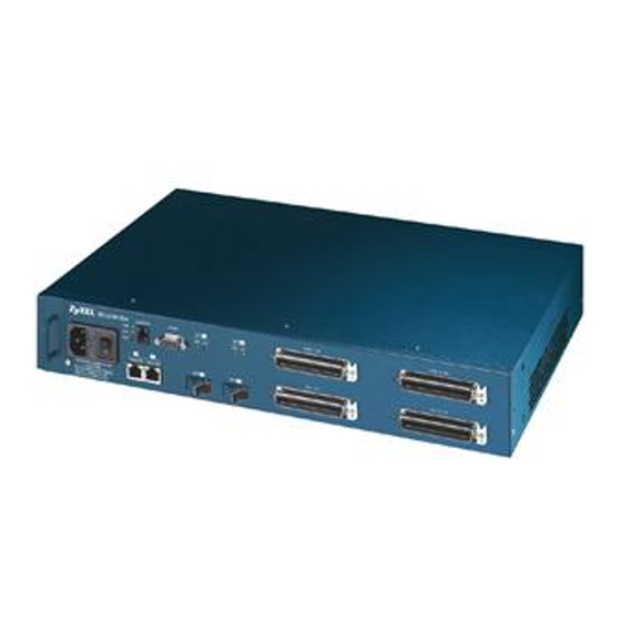
IES-1248 User’s Guide Chapter 3 Front Panel Connections This chapter explains how to make connections to the IES-1248’s front panel. 3.1 Front Panel (AC Power Version) The following figure shows the front panel of AC power version of the IES-1248. Figure 3-1 Front Panel (AC Power Version) 3.2 Front Panel (DC Power Version) The following figure shows the front panel of DC power version of the IES-1248. -
Page 40: Front Panel Leds
IES-1248 User’s Guide Table 3-1 IES-1248 Front Panel Ports CONNECTOR DESCRIPTION ALARM This DB9 connector has alarm input pins and alarm output pins. Connect the alarm input pins to alarm output terminals on other pieces of equipment. Connect the alarm output pins to an alarm input terminal on another piece of equipment. -
Page 41: Sfp Mini Gbic Slots
IES-1248 User’s Guide When auto-negotiation is turned on, an Ethernet port on the IES-1248 negotiates with the peer automatically to determine the connection speed and duplex mode. If the peer Ethernet port does not support auto-negotiation or turns off this feature, the IES-1248 determines the connection speed by detecting the signal on the cable and using half duplex mode. -
Page 42: Figure 3-4 Transceiver Installation
IES-1248 User’s Guide Insert the fiber-optic cables into the transceiver (you may need to remove cable dust covers). Insert the transceiver into the IES-1248’s SFP slot with the exposed section of PCB board facing down. Press the transceiver firmly until it clicks into place. Figure 3-4 Transceiver Installation Figure 3-5 Installed Transceivers 3.6.2... -
Page 43: Console Port Connection
IES-1248 User’s Guide Unlock the transceiver’s latch (latch styles vary). Pull the transceiver out of the slot. Put the transceiver’s dust cover on the transceiver. Figure 3-6 Opening the Transceiver Latch Figure 3-7 Removing the Transceiver 3.7 Console Port Connection For local management, you can use a computer with terminal emulation software configured to the following parameters: VT100 terminal emulation... -
Page 44: Alarm Connections
IES-1248 User’s Guide No parity, 8 data bits, 1 stop bit No flow control Connect the mini-RJ-11 male end of the console cable to the console port of the IES-1248. Connect the female end to a serial port (COM1, COM2 or other COM port) of your computer. 3.8 ALARM Connections A closed circuit on the ALARM input pins indicates an alarm. -
Page 45: Chapter 4 Mdf Connections
IES-1248 User’s Guide Chapter 4 MDF Connections This chapter shows you how to connect the Telco-50 connectors to an MDF. 4.1 MDF Connections Overview Observe the following before you start: Refer to the Hardware Specifications Appendix for the gauge of telephone wire to use. Follow the pin assignments shown in Hardware Specifications Appendix to wire Telco-50 cables to Telco- 50 connectors. -
Page 46: Telco-50 Cables
IES-1248 User’s Guide 4.3 Telco-50 Cables Telco-50 cables are used for data and voice applications with MDFs (Main Distribution Frame), patch panels and distribution boxes. They can also be used as extension cables. Telco-50 cables are made up of 25 twisted-pair copper wires. -
Page 47: Typical Mdf Scenarios
IES-1248 User’s Guide Figure 4-3 Installation Overview Example You can also attach RJ-11 connectors to the Telco-50 cable and connect directly to a DSL modem(s) or patch panel. This chapter discusses connections using MDFs. 4.6 Typical MDF Scenarios This section describes typical installation scenarios. 4.6.1 Installation Scenario A You want to install the IES-1248 in an environment where there are no previously installed MDFs. -
Page 48: Figure 4-4 Installation Scenario A
IES-1248 User’s Guide Figure 4-4 Installation Scenario A Procedure to Connect to an MDF Connect the Telco-50 connector end of the cable to the Telco-50 connector labeled USER. Connect the wiring on the other end of the Telco-50 cable to the upper ports of the MDF using a punch- down tool. -
Page 49: Figure 4-5 One Mdf For End-User And Co Connections
IES-1248 User’s Guide Figure 4-5 One MDF for End-user and CO Connections This installation scenario requires three MDFs. Please refer to the following figure for the connection schema. MDF 1 is the original MDF used for telephone connections only. MDF 2 is used for telephone connections only. MDF 3 is for DSL service connections. -
Page 50: Figure 4-7 Two Separate Mdfs For End-User And Co Connections
IES-1248 User’s Guide Procedure to Connect to MDFs Connect the Telco-50 connector end of the cable you want for DSL service to the Telco-50 connector labeled USER. Connect the wiring on the other side of the Telco-50 cable to the upper ports of MDF 3 using a punch- down tool. -
Page 51: Figure 4-8 Installation Scenario C
IES-1248 User’s Guide User A still has telephone service only. User B now has telephone and DSL service (see the following figure). Figure 4-8 Installation Scenario C Procedure to Connect to MDFs Connect the Telco-50 connector end of the cable you want for DSL service to the Telco-50 connector labeled USER. - Page 52 IES-1248 User’s Guide Connect the top ports of MDF 1 to the telephone company. MDF Connections...
-
Page 53: Chapter 5 Power Connections
IES-1248 User’s Guide Chapter 5 Power Connections This chapter shows you how to connect the IES-1248 to a power source. 5.1 Power Connections Overview Use the following procedures to connect the IES-1248 to a power source after you have installed it in a rack. Refer to power supply requirements in the Hardware Specifications Appendix and make sure you are using an appropriate power source. -
Page 54: Procedure To Turn On The Ies-1248 Power
IES-1248 User’s Guide Repeat the previous step for the IES-1248 terminal labeled +. 5.3 Procedure to Turn on the IES-1248 Power Turn on the power supply. Move the IES-1248 power switch to the on position. Power Connections... -
Page 55: Chapter 6 Fan Maintenance
IES-1248 User’s Guide Chapter 6 Fan Maintenance This chapter describes how to change a fan module. 6.1 Fan Maintenance Introduction The IES-1248 has a hot-swappable fan module. Use the following procedures to remove the fan module. Replace the entire fan module. Return any malfunctioning fan modules to the manufacturer. 6.2 Removing and Installing the Fan Module The IES-1248 fan module is at the left on the front panel. -
Page 56: Figure 6-2 Removing The Fan Module
IES-1248 User’s Guide Figure 6-2 Removing the Fan Module Figure 6-3 Fan Module Removed Fan Maintenance... - Page 57 Web Configurator Getting Started Part III: Web Configurator Getting Started This part introduces the web configurator and describes the Basic Setting web configurator screens.
-
Page 59: Chapter 7 Web Configurator Introduction
IES-1248 User’s Guide Chapter 7 Web Configurator Introduction This chapter tells how to access and navigate the web configurator. 7.1 Web Configurator Overview The web configurator allows you to use a web browser to manage the IES-1248. 7.2 Accessing the Web Configurator Use Internet Explorer 6 and later versions with JavaScript enabled. -
Page 60: Figure 7-2 Home Screen
IES-1248 User’s Guide Click Home to view current device statistics. Click Logout to exit the web configurator. Navigation Panel Figure 7-2 Home Screen In the navigation panel, click a main link to reveal a list of submenu links. Click a submenu link to go to the corresponding screen. -
Page 61: Table 7-1 Navigation Panel Sub-Links Overview
IES-1248 User’s Guide Table 7-1 Navigation Panel Sub-links Overview BASIC SETTING ADVANCED APPLICATION ROUTING PROTOCOL MANAGEMENT CONFIG SAVE The following table briefly describes the functions of the screens that you open by clicking the navigation panel’s sub-links. Table 7-2 Web Configurator Screens LABEL DESCRIPTION Basic Setting... - Page 62 IES-1248 User’s Guide Table 7-2 Web Configurator Screens LABEL DESCRIPTION Switch Setup Use this screen to set up global switch parameters such as IGMP snooping, MAC address learning, GARP and priority queues. IP Setup Use this screen to configure the system and management IP addresses and subnet masks.
-
Page 63: Saving Your Configuration
IES-1248 User’s Guide 7.4 Saving Your Configuration Click Apply in a configuration screen when you are done modifying the settings in that screen to save your changes back to the run time memory. Settings in the run time memory are lost when the IES-1248’s power is turned off. Click Config Save in the navigation panel to save your configuration to nonvolatile memory. -
Page 65: Chapter 8 Initial Configuration
IES-1248 User’s Guide Chapter 8 Initial Configuration This chapter describes initial configuration for the IES-1248. 8.1 Initial Configuration Overview This chapter shows what you first need to do to provide service to ADSL subscribers. 8.2 Initial Configuration This chapter uses the web configurator for initial configuration. See the commands part of this User’s Guide for information on the commands. -
Page 66: Figure 8-2 Basic Setting Ip Setup Menu
IES-1248 User’s Guide Click Basic Setting and then IP Setup. Figure 8-2 Basic Setting IP Setup Menu Use this screen to change the IP address, subnet mask, and default gateway IP address for your network. Apply the settings. Figure 8-3 IP Setup Skip to step 15 if you have your subscribers use VPI 0 and VCI 33 (the default for all of the ADSL ports). -
Page 67: Figure 8-4 Basic Setting Xdsl Port Setup Menu
IES-1248 User’s Guide Under Basic Setting, click xDSL Port Setup. Figure 8-4 Basic Setting xDSL Port Setup Menu Click VC Setup. Figure 8-5 xDSL Port Setup Click a virtual channel’s Select radio button and click Delete. Click OK in the next screen. -
Page 68: Figure 8-7 Select Ports
IES-1248 User’s Guide Click All and then Apply. Figure 8-7 Select Ports Select Super Channel to allow the channel to forward frames belonging to multiple VLAN groups (that are not assigned to other channels). Enter the VPI and VCI that you need. Leave the other default settings and click Add. -
Page 69: Figure 8-9 Copying The Pvc
IES-1248 User’s Guide Click the new channel’s Select radio button. Click Copy and then Paste. Figure 8-9 Copying the PVC Click All to select every port. Click Apply to paste the settings. Figure 8-10 Select Ports Click Config Save and Config Save. Figure 8-11 Config Save Menu Initial Configuration... -
Page 70: Default Settings
IES-1248 User’s Guide Click Save. Figure 8-12 Config Save Screen You can now use the device (with the other settings set to the defaults) to provide service to ADSL subscribers. See the rest of this chapter for information on other default settings. 8.3 Default Settings This table lists major default settings. - Page 71 IES-1248 User’s Guide Table 8-1 Default Settings Max Rate 512 Kbps 9088 Kbps Min Rate 32 Kbps 32 Kbps Interleave Delay 4 ms 4 ms Max SNR 31 db 31 db Min SNR 0 db 0 db Target SNR 6 db 6 db Virtual Channel Default Settings Super channel:...
-
Page 73: Chapter 9 Home And Port Statistics Screens
IES-1248 User’s Guide Chapter 9 Home and Port Statistics Screens This chapter describes the Home (status) and Port Statistics screens. 9.1 Home and Port Statistics Screens Overview The Home screen of the web configurator displays a port statistical summary with links to each port showing statistical details. - Page 74 IES-1248 User’s Guide Table 9-1 Home LABEL DESCRIPTION System up Time This field shows how long the system has been running since the last time it was started. The following fields are related to the Ethernet ports. ENET This field displays the number of the Ethernet port. Click a port number to display that port’s statistics screen (refer to 9.2.1).
-
Page 75: Figure 9-2 Ethernet Port Statistics
IES-1248 User’s Guide Figure 9-2 Ethernet Port Statistics The following table describes the labels in this screen. Table 9-2 Ethernet Port Statistics LABEL DESCRIPTION Return Click this link to go back to the Home screen. Port Use this drop-down list box to select a port for which you wish to view statistics. This field identifies the port described in this screen. - Page 76 IES-1248 User’s Guide Table 9-2 Ethernet Port Statistics LABEL DESCRIPTION rx multicast This field shows the number of good multicast frames received of 64 to 1518 octets in length (for non VLAN) or 1522 octets (for VLAN), not including Broadcast frames. Frames with range or length errors are also not taken into account.
- Page 77 IES-1248 User’s Guide Table 9-2 Ethernet Port Statistics LABEL DESCRIPTION tx jabber This field shows the number of frames transmitted that were longer than 1518 octets (non VLAN) or 1522 octets (VLAN) and contained an incorrect FCS value. tx oversize This field shows the number of frames transmitted that were bigger than 1518 octets (non VLAN) or 1522 (VLAN) and contained a valid FCS.
-
Page 78: Figure 9-3 Adsl Port Statistics
IES-1248 User’s Guide Figure 9-3 ADSL Port Statistics The following table describes the labels in this screen. Table 9-3 ADSL Port Statistics LABEL DESCRIPTION Return Click this link to go back to the Home screen. xDSL Port Use this drop-down list box to select a port for which you wish to view statistics. This field identifies the port described in this screen. - Page 79 IES-1248 User’s Guide Table 9-3 ADSL Port Statistics LABEL DESCRIPTION Tx discard This field shows the number of outgoing packets that were dropped on this port. The “Tx discard packets packets” counter always displays “0” because the IES-1248 does not discard packets that it sends.
-
Page 81: Chapter 10 Basic Setting Screens
IES-1248 User’s Guide Chapter 10 Basic Setting Screens This chapter describes how to configure the System Information, General Setup, Switch Setup, IP Setup and ENET Port Setup screens. 10.1 Basic Setting Screens Overview The System Information screen displays general switch information (such as firmware version number) and hardware polling information (such as fan status). -
Page 82: Figure 10-1 System Information
IES-1248 User’s Guide Figure 10-1 System Information The following table describes the labels in this screen. Table 10-1 System Information LABEL DESCRIPTION System Name This field displays the switch 's model name. 10-2 Basic Setting Screens... - Page 83 IES-1248 User’s Guide Table 10-1 System Information LABEL DESCRIPTION ZyNOS F/W Version This field displays the version number of the switch 's current firmware including the date created. DSP F/W Version This field displays the Digital Signal Processor firmware version number. This is the modem code firmware.
- Page 84 IES-1248 User’s Guide Table 10-1 System Information LABEL DESCRIPTION Fan Speed (RPM) A properly functioning fan is an essential component (along with a sufficiently ventilated, cool operating environment) in order for the device to stay within the temperature threshold. Each fan has a sensor that can detect and report the fan’s RPM (Rotations Per Minute).
-
Page 85: General Setup
IES-1248 User’s Guide 10.3 General Setup Click Basic Setting and General Setup in the navigation panel to display the screen as shown. Figure 10-2 General Setup The following table describes the labels in this screen. Table 10-2 General Setup LABEL DESCRIPTION Host Name Choose a descriptive name for identification purposes. -
Page 86: Igmp Snooping
IES-1248 User’s Guide Table 10-2 General Setup LABEL DESCRIPTION Use Time Server Enter the time service protocol that a timeserver sends when you turn on the switch. Not all When Bootup timeservers support all protocols, so you may have to use trial and error to find a protocol that works. -
Page 87: Switch Modes
IES-1248 User’s Guide destined for multicast groups that it does not know. IGMP snooping generates no additional network traffic, allowing you to significantly reduce multicast traffic passing through your switch. 10.5 Switch Modes The IES-1248 supports standalone and daisychain switch modes. 10.5.1 Standalone Switch Mode “Standalone switch mode”... -
Page 88: Figure 10-3 Port Isolation With Standalone Switch Mode Example
IES-1248 User’s Guide Figure 10-3 Port Isolation with Standalone Switch Mode Example 10.5.3 Daisychain Switch Mode Daisychain switch mode sets the IES-1248 to use Ethernet port one (ENET 1) as an uplink port to connect to the Ethernet backbone and Ethernet port two (ENET 2) to connect to another (daisychained or subtending) IES-1248. The daisychain switch mode is recommended for use in a network topology that does not have loops. -
Page 89: Switch Setup Screen
IES-1248 User’s Guide Figure 10-4 Port Isolation with Daisychain Switch Mode Example 10.6 Switch Setup Screen Click Basic Setting and then Switch Setup in the navigation panel to display the screen as shown. Figure 10-5 Switch Setup Basic Setting Screens 10-9... -
Page 90: Table 10-3 Switch Setup
IES-1248 User’s Guide The following table describes the labels in this screen. Table 10-3 Switch Setup LABEL DESCRIPTION IGMP Select Active to have the IES-1248 use IGMP snooping to dynamically learn multicast groups. Snooping MAC Address MAC address learning reduces outgoing traffic broadcasts. For MAC address learning to occur on a Learning port, the port must be active. -
Page 91: Ip Setup
IES-1248 User’s Guide Table 10-3 Switch Setup LABEL DESCRIPTION Level 7 Typically used for network control traffic such as router configuration messages. Level 6 Typically used for voice traffic that is especially sensitive to jitter (jitter is the variations in delay). Level 5 Typically used for video that consumes high bandwidth and is sensitive to jitter. -
Page 92: Enet Port Setup
IES-1248 User’s Guide Table 10-4 IP Setup LABEL DESCRIPTION Enter the IP address of your IES-1248 in dotted decimal notation for example 1.2.3.4. IP Mask Enter the IP subnet mask of your IES-1248 in dotted decimal notation for example 255.255.255.0. Apply IP Click Apply IP setting to save your changes to the device’s IP address and/or subnet mask to the setting... - Page 93 IES-1248 User’s Guide Table 10-5 ENET Port Setup LABEL DESCRIPTION Speed Mode Select the type of Ethernet connection for this port. When you don’t use auto-negotiation, you must make sure that the settings of the peer Ethernet port are the same in order to connect. Select Auto (auto-negotiation) to have the IES-1248 automatically determine the type of connection that the Ethernet port has.
-
Page 95: Chapter 11 Adsl Port Setup
IES-1248 User’s Guide Chapter 11 ADSL Port Setup This chapter explains how to configure settings for profiles and individual ADSL ports. It also covers how to configure virtual channels and virtual channel profiles. 11.1 ADSL Standards Overview Table 11-1 Maximum Transfer Rates of the ADSL Ports STANDARD MAXIMUM DOWNSTREAM MAXIMUM UPSTREAM... -
Page 96: Interleave Delay
IES-1248 User’s Guide 11.4 Interleave Delay Interleave delay is the wait (in milliseconds) that determines the size of a single block of data to be interleaved (assembled) and then transmitted. Interleave delay is used when transmission error correction (Reed- Solomon) is necessary due to a less than ideal telephone line. -
Page 97: Xdsl Port Setup
IES-1248 User’s Guide 11.7 xDSL Port Setup Click Basic Setting and then xDSL Port Setup in the navigation panel to open the following screen. Figure 11-1 xDSL Port Setup Table 11-2 xDSL Port Setup LABEL DESCRIPTION VC Setup Click VC Setup to open the VC Setup screen where you can configure VC settings for the DSL ports (see Figure 11-4). -
Page 98: Figure 11-2 Select Ports
IES-1248 User’s Guide Table 11-2 xDSL Port Setup LABEL DESCRIPTION 5. Click Apply to paste the settings. Figure 11-2 Select Ports Active Select this check box to copy this port’s active setting. This is configured in the xDSL Port Setting screen (see Figure 11-3). -
Page 99: Xdsl Port Setting
IES-1248 User’s Guide Table 11-2 xDSL Port Setup LABEL DESCRIPTION Select this check box to copy this port’s PVID and priority settings. These are configured in the PVID & Priority VLAN Port Setting screen (see the chapter on VLAN). Select this check box to copy this port’s packet filter settings. These are configured in the Packet Packet Filter Filtering screen (see the chapter on packet filtering). -
Page 100: Virtual Channels
IES-1248 User’s Guide Table 11-3 xDSL Port Setup LABEL DESCRIPTION Enter information to identify the subscriber connected to this ADSL port. You can use up to 31 Customer Info printable ASCII characters (including spaces and hyphens). Enter information to identify the telephone number of the subscriber connected to this ADSL port. Customer Tel You can use up to 15 ASCII characters (including spaces and hyphens). -
Page 101: Vc Setup Screen
IES-1248 User’s Guide Configure a channel on the port for voice service. Set the channel to use the PVID of the static VLAN you configured. Assign the channel a high priority. 11.9.1 Super Channel The IES-1248 forwards frames belonging to VLAN groups that are not assigned to specific channels to the super channel. -
Page 102: Figure 11-4 Vc Setup
IES-1248 User’s Guide Figure 11-4 VC Setup Table 11-4 VC Setup LABEL DESCRIPTION xDSL Port Setup Click xDSL Port Setup to go to the screen where you can configure DSL port settings (see Figure 11-1). Port Use this drop-down list box to select a port for which you wish to view or configure settings. - Page 103 IES-1248 User’s Guide Table 11-4 VC Setup LABEL DESCRIPTION Add, Apply Click Add to add channel settings on a port. Click Apply to save channel setting changes for a port. Clicking Add or Apply to saves your changes to the IES-1248’s volatile memory. The IES-1248 loses these changes if it is turned off or loses power, so use the Config Save link on the navigation panel to save your changes to the non-volatile memory when you are done configuring.
-
Page 104: Figure 11-5 Delete Other Channels
IES-1248 User’s Guide Table 11-4 VC Setup LABEL DESCRIPTION Delete Do the following to remove one or more PVCs. 1. Select a PVC’s Select radio button. 2. Click Delete. 3. Click OK if you want to remove the PVC from other ports. Click Cancel to only remove the one you selected. -
Page 105: Figure 11-7 Select Ports
IES-1248 User’s Guide Table 11-4 VC Setup LABEL DESCRIPTION Copy, Paste Do the following to copy settings from one PVC to another port or ports. Click the Select radio button of the PVC from which you want to copy settings. 2. -
Page 106: Figure 11-8 Port Profile
IES-1248 User’s Guide Figure 11-8 Port Profile Table 11-5 Port Profile LABEL DESCRIPTION VC Profile Click VC Profile to open the VC Profile screen where you can configure virtual channel profiles (see Figure 11-11). Alarm Profile Click Alarm Profile to open the Alarm Profile screen where you can configure limits that trigger an alarm when exceeded (see Figure 11-12) IGMP Filter Profile Click IGMP Filter Profile to open the IGMP Filter Profile screen where you can... - Page 107 IES-1248 User’s Guide Table 11-5 Port Profile LABEL DESCRIPTION Name When editing a profile, this is the name of this profile. When adding a profile, type a name (up to 31 characters) for the profile. Latency Mode This field sets the ADSL latency mode for the ports that belong to this profile. Select Fast mode to use no interleaving and have faster transmission (a “fast channel”).
-
Page 108: Atm Qos
IES-1248 User’s Guide Table 11-5 Port Profile LABEL DESCRIPTION Min SNR (db) Type the minimum downstream signal to noise margin (0-31 dB). Configure the minimum downstream signal to noise margin to be less than or equal to the maximum downstream signal to noise margin. - Page 109 IES-1248 User’s Guide The rt-VBR (real-time Variable Bit Rate) type is used with bursty connections that require closely controlled delay and delay variation. An example of an rt-VBR connection would be video conferencing. Video conferencing requires real-time data transfers and the bandwidth requirement varies in proportion to the video image’s changing dynamics.
-
Page 110: Figure 11-9 Pcr, Scr, Mcr And Mbs In Traffic Shaping
IES-1248 User’s Guide Figure 11-9 PCR, SCR, MCR and MBS in Traffic Shaping Cell Delay Variation Tolerance (CDVT) Cell Delay Variation Tolerance (CDVT) is the accepted tolerance of the difference between a cell’s transfer delay and the expected transfer delay. CDVT controls the time scale over which the PCR is enforced. CDVT is used to determine if a cell arrived too early in relation to PCR. -
Page 111: Figure 11-11 Vc Profile
IES-1248 User’s Guide 11.12.3 VC Profile Screen Click Basic Setting and then xDSL Profiles Setup in the navigation panel and then VC Profile to open the following screen. Figure 11-11 VC Profile Table 11-6 VC Profile LABEL DESCRIPTION Port Profile Click Port Profile to configure port profiles and assign them to individual ports (see Figure 11-8). - Page 112 IES-1248 User’s Guide Table 11-6 VC Profile LABEL DESCRIPTION SCR/MCR The Sustained Cell Rate (SCR) sets the average cell rate (long-term) that can be transmitted. SCR applies with the vbr traffic class. Minimum Cell Rate (MCR) is the minimum rate at which the sender can send cells. BT/NRM Burst Tolerance (BT) is the maximum number of cells that the port is guaranteed to handle without any discards.
-
Page 113: Figure 11-12 Alarm Profile
IES-1248 User’s Guide Use the top part of the screen (with the Add and Cancel buttons) to add or edit alarm profiles. The rest of the screen displays the configured alarm profiles. Figure 11-12 Alarm Profile Table 11-7 Alarm Profile LABEL DESCRIPTION Port Profile... - Page 114 IES-1248 User’s Guide Table 11-7 Alarm Profile LABEL DESCRIPTION Threshold Specify limits for the individual performance counters. The IES-1248 sends an alarm tram and generates a syslog entry when one of these thresholds is exceeded. A value of 0 disables the alarm threshold.
-
Page 115: Figure 11-13 Igmp Filter Profile
IES-1248 User’s Guide 11.12.5 IGMP Filter Profile Screen You can use the IGMP filter profiles to control access to a service that uses a specific multicast group (like a SIP server for example). Configure an IGMP filter profile that allows access to that multicast group. Then assign the IGMP filter profile to ADSL ports that are allowed to use the service. -
Page 116: Line Rate Information
IES-1248 User’s Guide Table 11-8 IGMP Filter Profile LABEL DESCRIPTION Port Profile Click Port Profile to configure port profiles and assign them to individual ports (see Figure 11-8). VC Profile Click VC Profile to open the VC Profile screen where you can configure virtual channel profiles (see Figure 11-11). -
Page 117: Figure 11-14 Line Rate Information
IES-1248 User’s Guide Figure 11-14 Line Rate Information Table 11-9 Line Rate Information LABEL DESCRIPTION Line Performance Click Line Performance to display an ADSL port’s line performance counters (see Figure 11-15). Line Data Click Line Data to display an ADSL port’s line bit allocation (see Figure 11-16). Port Use this drop-down list box to select a port for which you wish to view information. -
Page 118: Line Performance
IES-1248 User’s Guide Table 11-9 Line Rate Information LABEL DESCRIPTION Trellis Encoding This field displays whether Trellis encoding is turned on or off. Trellis encoding helps to reduce the noise in ADSL transmissions. Trellis may reduce throughput but it makes the connection more stable. -
Page 119: Figure 11-15 Line Performance
IES-1248 User’s Guide Figure 11-15 Line Performance Table 11-10 Line Performance LABEL DESCRIPTION Line Rate Click Line Rate to display an ADSL port’s line operating values (see Figure 11-14). Line Data Click Line Data to display an ADSL port’s line bit allocation (see Figure 11-16). Port Use this drop-down list box to select a port for which you wish to view information. - Page 120 IES-1248 User’s Guide Table 11-10 Line Performance LABEL DESCRIPTION Down/Up The Number of Errored Seconds transmitted (downstream) or received (upstream) on this ADSL Stream ES port. Down/Up The Number of Severely Errored Seconds transmitted (downstream) or received (upstream) on Stream SES this ADSL port.
-
Page 121: Line Data
IES-1248 User’s Guide 11.15 Line Data Click Basic Setting and Line Data in the navigation panel and then the Line Data link to open the following screen. This screen displays an ADSL port’s line bit allocation. Discrete Multi-Tone (DMT) modulation divides up a line’s bandwidth into tones. This screen displays the number of bits transmitted for each tone. - Page 122 IES-1248 User’s Guide Table 11-11 Line Data LABEL DESCRIPTION Bit Allocation “DS carrier load” displays the number (in hexadecimal format) of bits transmitted per DMT tone for the downstream channel (from the IES-1248 to the subscriber’s DSL modem or router). “US carrier load”...
- Page 123 Advanced Applications Part IV: Advanced Applications This part shows you how to configure the VLAN, IGMP Snooping, Static Multicast, Packet Filtering, Spanning Tree Protocol, Port Authentication, Port Security, DHCP Relay, Syslog and Access Control Advanced Application screens.
-
Page 125: Chapter 12 Vlan
IES-1248 User’s Guide Chapter 12 VLAN This chapter shows you how to configure IEEE 802.1Q tagged and port-based VLANs. 12.1 Introduction to VLANs A VLAN (Virtual Local Area Network) allows a physical network to be partitioned into multiple logical networks. Devices on a logical network belong to one group. - Page 126 IES-1248 User’s Guide 12.2.1 Forwarding Tagged and Untagged Frames Each port on the switch is capable of passing tagged or untagged frames. To forward a frame from an 802.1Q VLAN-aware switch to an 802.1Q VLAN-unaware switch, the switch first decides where to forward the frame and then strips off the VLAN tag.
-
Page 127: Vlan Status
IES-1248 User’s Guide Table 12-1 GARP Terminology VLAN TERM DESCRIPTION PARAMETER VLAN Type Permanent VLAN This is a static VLAN created manually. Dynamic VLAN This is a VLAN configured by a GVRP registration/deregistration process. VLAN Registration Fixed Fixed registration ports are permanent VLAN members. Administrative Registration Ports with registration forbidden are forbidden to join the specified VLAN. -
Page 128: Table 12-2 Vlan Status
IES-1248 User’s Guide The following table describes the labels in this screen. Table 12-2 VLAN Status LABEL DESCRIPTION Static VLAN Setting Click Static VLAN Setting to configure ports to dynamically join a VLAN group or permanently assign ports to a VLAN group or prohibit ports from joining a VLAN group (see Figure 12-1). -
Page 129: Figure 12-2 Static Vlan Setting
IES-1248 User’s Guide Figure 12-2 Static VLAN Setting The following table describes the labels in this screen. Table 12-3 Static VLAN Setting LABEL DESCRIPTION VLAN Status Click VLAN Status to see which of the IES-1248’s ports are members of which VLANs (see Figure 12-1) VLAN Port Click VLAN Port Setting to specify Port VLAN IDs (PVIDs). - Page 130 IES-1248 User’s Guide Table 12-3 Static VLAN Setting LABEL DESCRIPTION Delete Select the check boxes of the rule(s) that you want to remove in the Delete column and then click the Delete button. You cannot delete a VLAN if any PVIDs are set to use the VLAN or the VLAN is the CPU (management) VLAN.
-
Page 131: Figure 12-3 Vlan Port Setting
IES-1248 User’s Guide Figure 12-3 VLAN Port Setting Table 12-4 VLAN Port Setting LABEL DESCRIPTION VLAN Status Click VLAN Status to see which of the IES-1248’s ports are members of which VLANs (see Figure 12-1) Static VLAN Click Static VLAN to configure ports to dynamically join a VLAN group or permanently assign ports to a VLAN group or prohibit ports from joining a VLAN group (see Figure 12-1). -
Page 132: Figure 12-4 Select Ports
IES-1248 User’s Guide Table 12-4 VLAN Port Setting LABEL DESCRIPTION Apply Click Apply to save your changes to the IES-1248’s volatile memory. The IES-1248 loses these changes if it is turned off or loses power, so use the Config Save link on the navigation panel to save your changes to the non-volatile memory when you are done configuring. -
Page 133: Chapter 13 Igmp Snooping
IES-1248 User’s Guide Chapter 13 IGMP Snooping This chapter describes the IGMP Snooping screen. 13.1 IGMP Snooping IGMP (Internet Group Multicast Protocol) is a session-layer protocol used to establish membership in a multicast group - it is not used to carry user data. Refer to RFC 1112 and RFC 2236 for information on IGMP versions 1 and 2 respectively. - Page 134 IES-1248 User’s Guide Table 13-1 IGMP Snooping LABEL DESCRIPTION Report This is the total number of Report packets received. Leave This is the total number of Leave packets received. The Number of This is the number of IGMP groups that the IES-1248 has identified on the local network. IGMP Groups Page X of X This identifies which page of information is displayed and the total number of pages of...
-
Page 135: Chapter 14 Static Multicast
IES-1248 User’s Guide Chapter 14 Static Multicast This chapter describes the Static Multicast screen. 14.1 Static Multicast Filter Use the static multicast filter to allow incoming frames based on multicast MAC address(es) that you specify. This feature can be used in conjunction with IGMP snooping to allow multicast MAC address(es) that are not learned by IGMP snooping. - Page 136 IES-1248 User’s Guide Table 14-1 Static Multicast LABEL DESCRIPTION Index This is the static multicast group index number. MAC Address This is the multicast MAC address. 1~48, These fields display the static multicast group membership status of the ADSL ports. “V”...
-
Page 137: Chapter 15 Packet Filtering
IES-1248 User’s Guide Chapter 15 Packet Filtering This chapter describes how to configure the Packet Filter screen. 15.1 Packet Filter Configuration Click Advanced Application and then Filtering in the navigation panel to display the Packet Filter screen as shown next. Use this screen to set which types of packets the IES-1248 accepts on individual ADSL ports. Figure 15-1 Packet Filter The following table describes this screen. - Page 138 IES-1248 User’s Guide Table 15-1 Packet Filter LABEL DESCRIPTION IP Pass through Internet Protocol. The underlying protocol for routing packets on the Internet and other TCP/IP-based networks. ARP Pass through Address Resolution Protocol is a protocol for mapping an Internet Protocol address (IP address) to a physical computer address that is recognized in the local network.
-
Page 139: Chapter 16 Mac Filter
IES-1248 User’s Guide Chapter 16 MAC Filter This chapter introduces the MAC filter. 16.1 MAC Filter Introduction Use the MAC filter to allow only frames from MAC (Media Access Control) address(es) that you specify to come in through a port. 16.2 MAC Filter Configuration Click Advanced Application and then MAC Filter in the navigation panel to display the MAC Filter screen as shown next. - Page 140 IES-1248 User’s Guide Table 16-1 MAC Filter LABEL DESCRIPTION Type a device’s MAC address in hexadecimal notation (xx:xx:xx:xx:xx:xx, where x is a number from 0 to 9 or a letter from a to f) in this field. The MAC address must be a valid MAC address.
-
Page 141: Table 17-1 Path Cost
IES-1248 User’s Guide Chapter 17 Spanning Tree Protocol This chapter introduces the Rapid Spanning Tree Protocol (RSTP). 17.1 RSTP (Rapid Spanning Tree Protocol) and STP (Spanning Tree Protocol) RSTP adds rapid reconfiguration capability to STP. The Integrated Ethernet Switch supports RSTP and the earlier STP. -
Page 142: Figure 17-1 Stp Root Ports And Designated Ports
IES-1248 User’s Guide Figure 17-1 STP Root Ports and Designated Ports RSTP-aware devices exchange Bridge Protocol Data Units (BPDUs) periodically. When the bridged LAN topology changes, a new spanning tree is constructed. In RSTP, the devices send BPDUs every Hello Time. If an RSTP-aware device does not get a Hello BPDU after three Hello Times pass (or the Max Age), the device assumes that the link to the neighboring bridge is down. -
Page 143: Chapter 17 Spanning Tree Protocol
IES-1248 User’s Guide 17.2 STP Status Click Advanced Application and then Spanning Tree Protocol in the navigation panel to display the STP status as shown in the screen next. Figure 17-2 Spanning Tree Protocol: Status The following table describes the labels in this screen. Table 17-3 Spanning Tree Protocol: Status LABEL DESCRIPTION... - Page 144 IES-1248 User’s Guide Table 17-3 Spanning Tree Protocol: Status LABEL DESCRIPTION Time since change This is the time since the spanning tree was last reconfigured. Cost to root This is the path cost from the root port on this switch to the root switch. Root port ID This is the priority and number of the port on the switch through which this switch must communicate with the root of the Spanning Tree.
-
Page 145: Figure 17-3 Spanning Tree Protocol: Configuration
IES-1248 User’s Guide 17.2.1 Configuring STP Click Advanced Application and then Spanning Tree Protocol in the navigation panel to display the STP status. Click STP Config to display the Spanning Tree Protocol Configuration screen as shown next. Figure 17-3 Spanning Tree Protocol: Configuration The following table describes the labels in this screen. - Page 146 IES-1248 User’s Guide Table 17-4 Spanning Tree Protocol: Configuration LABEL DESCRIPTION Max Age This is the maximum time (in seconds) a switch can wait without receiving a BPDU before attempting to reconfigure. All switch ports (except for designated ports) should receive BPDUs at regular intervals.
-
Page 147: Chapter 18 Port Authentication
IES-1248 User’s Guide Chapter 18 Port Authentication This chapter describes the 802.1x authentication method and RADIUS server connection setup. 18.1 Introduction to Authentication IEEE 802.1x is an extended authentication protocol3 that allows support of RADIUS (Remote Authentication Dial In User Service, RFC 2138, 2139) for centralized user profile management on a network RADIUS server. 18.1.1 RADIUS RADIUS (Remote Authentication Dial-In User Service) authentication is a popular protocol used to authenticate... -
Page 148: Figure 18-2 Port Authentication: Radius
IES-1248 User’s Guide Figure 18-2 Port Authentication: RADIUS The following table describes the labels in this screen. Table 18-1 Port Authentication: RADIUS LABEL DESCRIPTION 802.1x Click 802.1x to configure individual port authentication settings (see Figure 18-3). Enable Select this check box to have the IES-1248 use an external RADIUS server to authenticate Authentication users. -
Page 149: Figure 18-3 Port Authentication: 802.1X
IES-1248 User’s Guide Table 18-1 Port Authentication: RADIUS LABEL DESCRIPTION Click Add to save your changes to the IES-1248’s volatile memory. The IES-1248 loses these changes if it is turned off or loses power, so use the Config Save link on the navigation panel to save your changes to the non-volatile memory when you are done configuring. -
Page 150: Table 18-2 Port Authentication: 802.1X
IES-1248 User’s Guide Table 18-2 Port Authentication: 802.1x LABEL DESCRIPTION RADIUS/Local Click this link to configure the RADIUS server or local profile settings (see Figure 18-2). Profile Enable Select this check box to turn on IEEE 802.1x authentication on the switch. Authentication Port This field displays a port number. -
Page 151: Chapter 19 Port Security
IES-1248 User’s Guide Chapter 19 Port Security This chapter shows you how to set up port security. 19.1 About Port Security Port security allows you to restrict the number of MAC addresses that can be learned on a port. The switch can learn up to 56K MAC addresses in total. - Page 152 IES-1248 User’s Guide Table 19-1 Port Security LABEL DESCRIPTION Limited Number of Specify how many MAC addresses the IES-1248 can learn on this port. The range is 1~1024. Learned MAC If you also use MAC filtering on a port, it is recommended that you set this limit Address to be equal to or greater than the number of MAC filter entries you configure.
-
Page 153: Chapter 20 Dhcp Relay
IES-1248 User’s Guide Chapter 20 DHCP Relay This chapter shows you how to set up DHCP relay. 20.1 DHCP Relay DHCP (Dynamic Host Configuration Protocol, RFC 2131 and RFC 2132) allows individual clients to obtain TCP/IP configuration at start-up from a DHCP server. You can configure the IES-1248 to relay client TCP/IP configuration requests to a DHCP server and the server’s responses back to the clients. -
Page 154: Figure 20-2 Dhcp Relay
IES-1248 User’s Guide Figure 20-2 DHCP Relay The following table describes the labels in this screen. Table 20-1 DHCP Relay LABEL DESCRIPTION Enable DHCP Enable DHCP relay to have the Integrated Ethernet Switch relay client TCP/IP configuration Relay: requests to a DHCP server and the server’s responses back to the clients. Remote DHCP Type the IP address of the DHCP server to which the Integrated Ethernet Switch should relay server IP... -
Page 155: Chapter 21 Syslog
IES-1248 User’s Guide Chapter 21 Syslog This chapter explains how to set the syslog parameters. 21.1 Syslog The syslog feature sends logs to an external syslog server. 21.2 Syslog Setup Click Advanced Application and then Syslog in the navigation panel to display the screen shown next. Figure 21-1 Syslog The following table describes the labels in this screen. -
Page 157: Chapter 22 Access Control
IES-1248 User’s Guide Chapter 22 Access Control This chapter describes how to configure access control. 22.1 About Access Control Click Advanced Application and then Access Control from the navigation panel to display the screen as shown. From this screen you can configure SNMP and enable/disable remote service access. Figure 22-1 Access Control 22.2 Access Control Overview A console port session and a Telnet session cannot coexist. -
Page 158: Figure 22-3 Snmp Management Model
IES-1248 User’s Guide IES-1248 through the network via SNMP version one (SNMPv1) and/or SNMP version 2c. The next figure illustrates an SNMP management operation. SNMP is only available if TCP/IP is configured. Figure 22-3 SNMP Management Model An SNMP managed network consists of two main components: agents and a manager. An agent is a management software module that resides in a managed switch (the IES-1248). -
Page 159: Table 22-3 Rfc-1215 Snmp Traps
MIBs let administrators collect statistics and monitor status and performance. The IES-1248 supports the following MIBs: MIB II IF MIB and ADSL line MIB (RFC-2662) SNMP MIB II (RFC-1215) BRIDGE MIB: dot1dStp (RSTP), dot1dGarp (GARP) The IES-1248 can also respond with specific data from the ZyXEL private MIBs: zyxel.mib zyxel-AS-ATM.mib zyxel-AS.mib zyxel-AESCommon.mib zyxel-iesCommon.mib... -
Page 160: Figure 22-4 Access Control: Snmp
This trap is sent when the Unavailable seconds-line 15-minute threshold is reached. 22.3.4 ZyXEL Private MIB SNMP Traps The IES-1248 can also send the following SNMP traps that are defined in the ZyXEL private MIBs. Table 22-5 ZyXEL Private MIB SNMP Traps TRAP... -
Page 161: Figure 22-5 Access Control: Logins
IES-1248 User’s Guide Table 22-6 Access Control: SNMP LABEL DESCRIPTION Return Click Return to go back to the previous screen. Get Community Enter the get community, which is the password for the incoming Get- and GetNext- requests from the management station. Set Community Enter the set community, which is the password for incoming Set- requests from the management station. -
Page 162: Service Access Control Configuration
IES-1248 User’s Guide Table 22-7 Access Control: Logins LABEL DESCRIPTION Return Click Return to go back to the previous screen. Administrator This is the default administrator account with the “admin” user name. You cannot change the default administrator user name. Old Password Type the existing system password ("1234"... -
Page 163: Secured Client Configuration
IES-1248 User’s Guide Table 22-8 Access Control: Service Access Control LABEL DESCRIPTION Enable Select the Enable check boxes for the corresponding services that you want to allow to access the IES-1248. Server Port For Telnet, FTP or web services, you may change the default service port by typing the new port number in the Server Port field. - Page 164 IES-1248 User’s Guide Table 22-9 Secured Client Setup LABEL DESCRIPTION Start Address Configure the IP address range of trusted computers from which you can manage the IES-1248. End Address The IES-1248 checks if the client IP address of a computer requesting a service or protocol matches the range set here.
- Page 165 Routing Protocol and Management Part V: Routing Protocol and Management This part describes the Routing Protocol and Management screens.
-
Page 167: Chapter 23 Routing Protocol
IES-1248 Ethernet Switch Chapter 23 Routing Protocol This chapter shows you how to configure the static routing function. 23.1 Static Route Static routes tell the IES-1248 how to forward the IES-1248’s own IP traffic when you configure the TCP/IP parameters manually. This is generally useful for allowing management of the switch from a device with an IP address on a different subnet from that of the switch’s IP address (remote management). -
Page 168: Figure 23-2 Static Routing: Summary Table
IES-1248 Ethernet Switch Table 23-1 Static Routing LABEL DESCRIPTION IP Subnet Mask Enter the subnet mask for this destination. Gateway IP Enter the IP address of the gateway. The gateway is an immediate neighbor of your switch that Address will forward the packet to the destination. The gateway must be a router on the same segment as your switch. - Page 169 IES-1248 Ethernet Switch Table 23-2 Static Routing: Summary Table LABEL DESCRIPTION Gateway Address This field displays the IP address of the gateway. The gateway is an immediate neighbor of your switch that will forward the packet to the destination. Metric This field displays the cost of transmission for routing purposes.
-
Page 171: Chapter 24 Maintenance
IES-1248 Ethernet Switch Chapter 24 Maintenance This chapter explains how to use the maintenance screens. 24.1 Maintenance Click Management and then Maintenance in the navigation panel to open the following screen. Figure 24-1 Maintenance 24.2 Firmware Upgrade From the Maintenance screen, use Firmware Upgrade to upgrade your switch firmware. See the System Info screen to verify your current firmware version number. -
Page 172: Restore A Text Configuration File
IES-1248 Ethernet Switch 24.3 Restore a Text Configuration File From the Maintenance screen, use Restore Text Configuration to open the following screen where you can save a configuration file from your computer to the switch. Figure 24-3 Restore Configuration Type the path and file name of the configuration file you wish to restore in the File Path text box or click Browse to display a Choose File screen from which you can locate it. -
Page 173: Reboot System
IES-1248 Ethernet Switch Figure 24-4 Confirm Restore Factory Default Settings Click OK to begin resetting all switch configurations to the factory defaults and then wait for the switch to restart. This takes up to two minutes. If you want to access the switch web configurator again, you may need to change the IP address of your computer to be in the same subnet as that of the default switch IP address (192.168.1.1).Click Figure 24-5 Restart After Load Factory Defaults 24.6 Reboot System... -
Page 175: Chapter 25 Diagnostic
IES-1248 Ethernet Switch Chapter 25 Diagnostic This chapter explains the Diagnostic screens. 25.1 Diagnostic Click Management and then Diagnostic in the navigation panel to display this screen. Use this screen to check system logs, ping IP addresses or perform loopback tests. Figure 25-1 Diagnostic The following table describes the labels in this screen. -
Page 176: Log Format
IES-1248 Ethernet Switch Table 25-1 Diagnostic LABEL DESCRIPTION Syslog/ Event Log Click Display to display a log of events in the multi-line text box. Click Clear to empty the text box and reset the syslog entry. IP Ping Type the IP address of a device that you want to ping in order to test a connection. In the field to the right specify the number of times that you want to ping the IP address. -
Page 177: Table 25-3 Log Messages
IES-1248 Ethernet Switch Table 25-3 Log Messages LOG MESSAGE TYPE DESCRIPTION ADSLLink INFO An ADSL port established a connection. Up(SN= ): - port number / ! - sequence number of the connection - downstream rate ADSL Link Info: ... -
Page 178: Line Diagnostics Test Parameters
IES-1248 Ethernet Switch Table 25-3 Log Messages LOG MESSAGE TYPE DESCRIPTION THERMO OVER WARN The voltage went outside of the accepted operating range. VOLTAGE:- nominal voltage of the DC power nominal: (m V) value: - voltage of the DC power when logged mV)! THERMO OVER VOLTAGE INFO... - Page 179 IES-1248 Ethernet Switch Table 25-4 Line Diagnostics Test Parameters LABEL DESCRIPTION The Quiet Line Noise for a DMT sub-carrier is the rms (root mean square) level of the noise present on the line, when no ADSL signals are present. It is measured in dBm/Hz. The QLN can be used in analyzing crosstalk.
-
Page 181: Chapter 26 Mac Table
IES-1248 Ethernet Switch Chapter 26 MAC Table This chapter introduces the MAC Table. 26.1 Introduction to MAC Table The MAC table lists device MAC addresses that are dynamically learned by the IES-1248. The table shows the following for each MAC address: the port upon which Ethernet frames were received from the device, to which VLAN groups the device belongs (if any) and to which channel it is connected (for devices connected to DSL ports). -
Page 182: Viewing The Mac Table
IES-1248 Ethernet Switch Figure 26-1 MAC Table Filtering Flowchart 26.2 Viewing the MAC Table Click Management in the navigation panel and then MAC Table to display the following screen. 26-2 MAC Table... -
Page 183: Figure 26-2 Mac Table
IES-1248 Ethernet Switch Figure 26-2 MAC Table The following table describes the labels in this screen. Table 26-1 MAC Table LABEL DESCRIPTION Get Time This displays the date and time that the displayed MAC address information was last updated. The date is in year, month and day format. The time is in (24-hour) hour, minute and second format. - Page 184 IES-1248 Ethernet Switch Table 26-1 MAC Table LABEL DESCRIPTION Refresh Click Refresh to update the list of dynamically learned MAC addresses. Flush Click Flush to remove all of the dynamically learned MAC address entries from the MAC table. 26-4 MAC Table...
-
Page 185: Chapter 27 Arp Table
IES-1248 Ethernet Switch Chapter 27 ARP Table This chapter describes the ARP Table. 27.1 Introduction to ARP Table Address Resolution Protocol (ARP) is a protocol for mapping an Internet Protocol address (IP address) to a physical machine address, also known as a Media Access Control or MAC address, on the local area network. An IP (version 4) address is 32 bits long. -
Page 186: Table 27-1 Arp Table
IES-1248 Ethernet Switch Table 27-1 ARP Table LABEL DESCRIPTION Flush Click Flush to remove all of the entries from the ARP table. Total X ARP This displays the number of entries in the ARP table. Entries Page X of X This identifies which page of information is displayed and the total number of pages of information. - Page 187 Commands and SNMP Part VI: Commands and SNMP This part gives information on how to use commands to configure and manage the IES-1248. It also provides information about SNMP.
-
Page 189: Chapter 28 Commands
IES-1248 User’s Guide Chapter 28 Commands This chapter introduces the command line interface and lists the available commands. 28.1 Command Line Interface Overview See the web configurator parts of this User’s Guide for background information on features configurable by web configurator. You can use text command lines for software configuration. -
Page 190: Table 28-1 Commands
IES-1248 User’s Guide Table 28-1 Commands COMMAND DESCRIPTION info show Displays general system information. hostnameSets the system name. location Sets location information. contact Sets contact person information. passwd Sets the system’s administrator password. reboot [show|sec|cancel Sets the reboot timer or displays the timer and remaining time for reboot. -
Page 191
IES-1248 User’s Guide Table 28-1 Commands COMMAND DESCRIPTION enable
Allows a secured client set to manage the device. disable Stops a secured client set from managing the device. Sets a secured client set: a [[telnet] range of IP addresses from [ftp] [web] [icmp]] which you can manage the... -
Page 192
IES-1248 User’s Guide Table 28-1 Commands COMMAND DESCRIPTION show Displays the device’s logs. clear Clears the device’s logs. wdog show Displays the current watchdog firmware protection feature status and timer.
-
Page 193
IES-1248 User’s Guide Table 28-1 Commands COMMAND DESCRIPTION disable
Turns off the specified ADSL ports. profile show [profile] Displays profile contents. ]> [ ... -
Page 194
IES-1248 User’s Guide Table 28-1 Commands COMMAND DESCRIPTION See section 39.3 for how to configure Permanent Virtual Circuits. show [portlist] [
Displays PVC settings. ] Creates or modifies a PVC setting. delete Removes a PVC setting. -
Page 195
IES-1248 User’s Guide Table 28-1 Commands COMMAND DESCRIPTION showport
Displays which alarm profile parameters are mapped to an ADSL port. annexl enable Turns on the Annex L feature on the specified port(s). disable Turns off the Annex L feature on the specified port(s). -
Page 196
IES-1248 User’s Guide Table 28-1 Commands COMMAND DESCRIPTION profile set
Configures an IGMP filter profile. delete Removes an IGMP filter profile. show [ |*] Displays an IGMP filter profile’s settings. queuemap show Displays the system’s priority level to physical queue mapping. -
Page 197
IES-1248 User’s Guide Table 28-1 Commands COMMAND DESCRIPTION show Displays DHCP relay settings. enable Turns on DHCP relay. disable Turns off DHCP relay. server
Sets a DHCP relay server IP address entry. option82 enable Turns on the DHCP relay agent information (Option 82) feature. -
Page 198
IES-1248 User’s Guide Table 28-1 Commands COMMAND DESCRIPTION set
Sets the VLAN ID of the management VLAN. flush Clears learned MAC addresses from the forwarding table. agingtime show Displays the MAC aging out time period. Sets the MAC aging out time -
Page 199
IES-1248 User’s Guide Table 28-1 Commands COMMAND DESCRIPTION auth
Turns on IEEE 802.1X for specific ports. disable Turns off IEEE 802.1X for specific ports. -
Page 200
IES-1248 User’s Guide Table 28-1 Commands COMMAND DESCRIPTION disable
Turns off the specified Ethernet port(s). smcast Use the static multicast filter to pass routing protocols, such as RIP and OSPF. show Display all MAC addresses joined to ADSL ports. ... -
Page 201
IES-1248 User’s Guide Table 28-1 Commands COMMAND DESCRIPTION show Displays the routing table.
[/netmask] Adds a routing table entry. [metric] default route. delete [/netmask] Removes a routing table entry. -
Page 202
IES-1248 User’s Guide Table 28-1 Commands COMMAND DESCRIPTION Displays a management port’s status and performance data. config show
-
Page 203: Chapter 29 Command Examples
IES-1248 User’s Guide Chapter 29 Command Examples This chapter gives some examples of commands. 29.1 Command Examples Overview These are commands that you may use frequently in configuring and maintaining your IES-1248. See section 31.1 for commands that deal with the IEEE 802.1Q tagged VLAN. 29.2 Sys Commands These are the commonly used commands that belong to the sys (system) group of commands. -
Page 204: Statistics Monitor Command
IES-1248 User’s Guide This command shows general system settings, the RAS code, firmware version, system uptime and bootbase version. An example is shown next. ras> sys info show hostname : ras location contact model : IES-1248 ZyNOS version : V3.50(LS.0)b8 | 07/06/2004 mac address : 00:A0:C5:4D:FB:A1 ras size... -
Page 205: Statistics Port Command
IES-1248 User’s Guide 29.4 Statistics Port Command Syntax: ras> statistics port[ ] [clear] where You can specify a single port <1>, all ports <*> or a list of ports <1,3,enet1>. You can also include a range of ports <1,5,6~10,enet1,enet2>. ... -
Page 207: Chapter 30 Dhcp Relay Commands
IES-1248 User’s Guide Chapter 30 DHCP Relay Commands This chapter describes how to use the DHCP Relay commands. 30.1 DHCP Relay Overview DHCP (Dynamic Host Configuration Protocol, RFC 2131 and RFC 2132) allows individual clients to obtain TCP/IP configuration at start-up from a DHCP server. You can configure the IES-1248 to relay client TCP/IP configuration requests to a DHCP server and the server’s responses back to the clients. -
Page 208: Dhcp Relay Option 82 (Agent Information)
IES-1248 User’s Guide 30.2.4 Show Command Syntax: switch dhcprelay show command displays whether or not the DHCP relay feature is activated, the DHCP server’s IP address , show the status of the DHCP relay agent info option 82 feature and the information configured for it. ras>... - Page 209 IES-1248 User’s Guide The option82 command adds the specified information for the relay agent. DHCP Relay Commands 30-3...
-
Page 211: Chapter 31 Ieee 802.1Q Tagged Vlan Commands
IES-1248 User’s Guide Chapter 31 IEEE 802.1Q Tagged VLAN Commands This chapter describes the IEEE 802.1Q Tagged VLAN and associated commands. 31.1 IEEE 802.1Q Tagged VLAN Overview See the web configurator chapter on VLAN for more information on VLANs. There are two kinds of tagging: 1. -
Page 212: Figure 31-1 Garptimer Show Command Example
IES-1248 User’s Guide 31.3.1 Garptimer Show Command Syntax: ras> switch garptimer show This command shows the management switch card’s GARP timer settings, including the join, leave and leave all timers. An example is shown next. ras> switch garptimer show join time (ms): 200 leave time (ms): 600... -
Page 213: Figure 31-3 Garptimer Leave Command Example
IES-1248 User’s Guide= has a single Leave Period timer. Leave Time must be two times larger than Join Timer; the default is 600 milliseconds. This command sets the management switch card’s leave period timer for GVRP in milliseconds. -
Page 214: Figure 31-5 Vlan Port Show Command Example
IES-1248 User’s Guide The following example shows the settings for ADSL port 1. ras> switch vlan portshow 1 port pvid priority frametype gvrp ----- ---- -------- --------- ---- Figure 31-5 VLAN Port Show Command Example 31.3.6 VLAN PVID Command Syntax: switch vlan pvid... -
Page 215: Figure 31-7 Modifying The Static Vlan Example
IES-1248 User’s Guidestands for a registrar administration control flag and registers a fixed to the static VLAN table with . For a fixed port, you also have to specify ... -
Page 216: Figure 31-8 Vlan Frame Type Command Example
IES-1248 User’s Guide An untagged frame comes in from the LAN. The IES-1248 checks the PVID table and assigns a temporary VID. The IES-1248 ignores the port from which the frame came, because the IES-1248 does not send a frame to the port from which it came. -
Page 217: Figure 31-9 Cpu Vlan Configuration And Activation Example
IES-1248 User’s Guide 31.3.10 VLAN CPU Set Command Syntax: switch vlan cpu setwhere = The VLAN ID. Valid parameter range = [1 – 4094]. This must be the VLAN ID of a VLAN that is already configured. The VLAN must also have at least one port set to the fixed status. -
Page 218: Vlan Enable
IES-1248 User’s Guide 31.3.12 VLAN Priority Command Syntax: switch vlan prioritywhere = You can specify a single port: <1>, all ports: <*>, a list of ports: <1,3,enet1>, you can also include a range of ports: <1,5,6~10,enet1,enet2>. = This is the priority value (0 to 7) to use for incoming frames with an IEEE 802.1Q VLAN tag. -
Page 219: Vlan Disable
IES-1248 User’s Guide 31.5 VLAN Disable Syntax: switch vlan disableThis command disables the specified VLAN ID in the SVLAN (Static VLAN) table. You cannot disable a VLAN if any PVIDs are set to use the VLAN or the VLAN is the CPU (management) VLAN. 31.5.1 VLAN Show Command Syntax:... -
Page 221: Chapter 32 Mac Commands
IES-1248 User’s Guide Chapter 32 MAC Commands This chapter describes how to configure the IES-1248’s MAC commands. 32.1 MAC Commands Overview Use the MAC commands to configure MAC filtering and limit the MAC count. 32.2 MAC Filter Commands Use the MAC filter commands to allow only incoming frames from MAC (Media Access Control) address(es) that you specify. - Page 222 IES-1248 User’s Guide This command turns on the MAC filtering feature on the specified ADSL port(s) or on all ADSL ports if no port is specified. The following example turns on the MAC filtering feature on ADSL port 5. ras> switch mac filter enable 5 32.2.3 MAC Filter Disable Command Syntax:...
-
Page 223: Mac Count Commands
IES-1248 User’s Guide The following example removes the source MAC address of 00:a0:c5:12:34:56:78 from the MAC filter for ADSL port 5. ras> switch mac filter delete 5 0:a0:c5:12:34:56:78 32.3 MAC Count Commands Use MAC count commands to limit how many MAC addresses may be dynamically learned or statically configured on an ADSL port. -
Page 224
IES-1248 User’s Guide 32.3.3 MAC Count Disable Command Syntax: switch mac count disable
where You can specify a single ADSL port <1>, all ADSL ports <*> or a list of ADSL ports <1,3,5>. You can also include a range of ports <1,5,6~10>. This command disables the MAC filtering feature on the specified ADSL port(s). -
Page 225: Chapter 33 Igmp Filter Commands
IES-1248 User’s Guide Chapter 33 IGMP Filter Commands This chapter describes the IGMP filter commands. 33.1 IGMP Filter Commands Use the IGMP filter commands to define IGMP filter profiles and assign them to ADSL ports. IGMP filter profiles allow you to control access to IGMP multicast groups. You can have a service available to a specific IGMP multicast group. -
Page 226
IES-1248 User’s Guide The following example sets ADSL port 9 to use the voice IGMP filter profile. ras> switch igmpfilter set 9 voice 33.1.3 IGMP Filter Profile Set Command Syntax: switch igmpfilter profile set
where = Specify a name to identify the IGMP filter profile (you cannot change the name of ... -
Page 227: Figure 33-2 Igmp Filter Show Command Example
IES-1248 User’s Guide where [|*]= The name of an IGMP filter profile or all of the IGMP filter profiles <*> . This command displays an IGMP filter profile’s settings. The following example displays the voice IGMP filter profile’s settings. ras> switch igmpfilter profile show voice profile index startip... -
Page 229: Chapter 34 Packet Filter Commands
IES-1248 User’s Guide Chapter 34 Packet Filter Commands This chapter describes the packet filter commands. 34.1 Packet Filter Commands Use the following packet filter commands to filter out specific types of packets on specific ports. 34.1.1 Packet Filter Show Command Syntax: switch pktfilter show [portlist] where... - Page 230 IES-1248 User’s Guide [ip] Reject IP packets. Internet Protocol. The underlying protocol for routing packets on the Internet and other TCP/IP-based networks. [arp] Reject ARP packets. Address Resolution Protocol is a protocol for mapping an Internet Protocol address (IP address) to a physical computer address that is recognized in the local network.
-
Page 231: Chapter 35 Ip Commands
IES-1248 User’s Guide Chapter 35 IP Commands This chapter shows you how to use the (standard shell) IP commands to configure the IP (Internet Protocol) parameters. 35.1 IP Commands Introduction Use the IES-1248’s management IP addresses to manage it through the network. 35.2 IP Settings and Default Gateway Use the following command sequence to set the IES-1248’s IP settings for the Ethernet 1 and 2, and DSL ports, VID and default gateway. -
Page 232: General Ip Commands
IES-1248 User’s Guide Figure 35-1 IP Settings and Default Gateway Address The IES-1248 leaves the factory with a default (in-band) management IP address of 192.168.1.1 and a subnet mask of 255.255.255.0, (ff:ff:ff:00 in hexadecimal notation), and the default gateway set at 192.168.1.254. Make sure that you configure the IP parameters correctly before you connect an IES-1248 to the network, otherwise, you may interrupt services already running. -
Page 233: Figure 35-2 Route Show Command Example
IES-1248 User’s Guide whereThe destination IP address of packets that this static route is to route. [/netmask] The destination subnet mask of packets that this static route is to route. The IP address of the gateway that you want to send the packets through. [metric] The metric (hop count) of this static route. -
Page 234: Statistics Ip Command
IES-1248 User’s Guide This command displays the IES-1248’s IP Address Resolution Protocol table. This is the list of IP addresses and matching MAC addresses that the IES-1248 has resolved. An example is shown next. ras> ip arp show mac address --------------- ----------------- 172.23.14.254... -
Page 235: Chapter 36 Firmware And Configuration File Maintenance
VLANs and so on. It arrives from ZyXEL with a “dat” filename extension. ZyNOS (ZyXEL Network Operating System sometimes referred to as the “ras” file) is the system firmware and has a “bin” filename extension. The configuration file has a “rom” filename extension. With many FTP and clients, the filenames are similar to those shown next. -
Page 236: Editable Configuration File
IES-1248 User’s Guide Table 36-1 Filename Conventions FILE TYPE INTERNAL NAME EXTERNAL NAME DESCRIPTION Configuration config-0 *.dat This is the configuration filename for the IES-1248. File Firmware *.bin This is the generic name for the ZyNOS firmware on the IES-1248. 36.3 Editable Configuration File The configuration file can be downloaded as a plain-text (ASCII) file. -
Page 237: Figure 36-1 Configuration File Example
IES-1248 User’s Guide #### sysinfo sys info hostname ras sys info location taiwan sys info contact zmlin #### snmp sys snmp getcommunity public sys snmp setcommunity public sys snmp trapcommunity 1234 sys snmp trustedhost 0.0.0.0 sys snmp trapdst 172.23.15.250 #### server sys server enable telnet sys server enable ftp sys server enable web... -
Page 238: Firmware File Upgrade
IES-1248 User’s Guide 36.3.3 Editable Configuration File Upload You can upload the configuration file by following the steps below. Use an FTP client to connect to the IES-1248. C:\> ftpEnter the User name (just press [ENTER]). User: [ENTER] Enter the management password (1234 by default). -
Page 239: Chapter 37 Snmp
IES-1248 User’s Guide Chapter 37 SNMP This chapter covers Simple Network Management Protocol (SNMP) with the IES-1248. 37.1 SNMP Overview SNMP (Simple Network Management Protocol) is a protocol used for exchanging management information between network devices. The IES-1248 supports SNMP versions one and two (SNMPv1 and SNMPv2) agent functionality, which allows a manager station to manage and monitor it through the network. -
Page 240
IES-1248 User’s Guide sys snmp trusthost set
where The IP address of a trusted host. Use this command to add the host IP address to the list of trusted hosts. If you enter a trusted host, your IES-1248 will only respond to SNMP messages from this address. -
Page 241: Chapter 38 Adsl Commands
IES-1248 User’s Guide Chapter 38 ADSL Commands This chapter describes some of the ADSL commands that allow you to configure and monitor the ADSL ports. 38.1 ADSL Standards Overview See the web configurator chapter on ADSL for background information. Refer to Chapter 1for the settings of the default profile and ADSL port default settings. -
Page 242: Figure 38-1 Adsl Show Command Example
IES-1248 User’s Guide The following example displays information on ADSL port 5. ras> adsl show 1 port enable mode up/downstream profile ---- ------ -------- ------------- ------------------------------- auto 512/ 9088 max Subscriber Info: port name ---- -------------------------------- ---------------- Figure 38-1 ADSL Show Command Example 38.4.2 ADSL Enable Command Syntax:... -
Page 243: Figure 38-2 Adsl Profile Show Command Example
IES-1248 User’s Guide = A profile name.This command displays the specified ADSL profile or all ADSL profiles if you do not specify one. The following example displays the ADSL DEFVAL profile. ras> adsl profile show DEFVAL 01. DEFVAL latency mode: interleave up stream down stream --------- -----------... - Page 244 IES-1248 User’s Guide The profile is a table that contains information on ADSL line configuration. Each entry in this table reflects a parameter defined by a manager, which can be used to configure the ADSL line. Note that the default value will be used for any of the above fields that are omitted. The upstream rate must be less than or equal to the downstream rate.
-
Page 245
IES-1248 User’s Guide adsl profile map
= You can specify a single ADSL port <1>, all ADSL ports <*> or a list of ADSL ports <1,3,5>. You can also include a range of ports <1,5,6~10>. ... -
Page 246: Statistics Adsl Commands
IES-1248 User’s Guide where= You can specify a single ADSL port <1>, all ADSL ports <*> or a list of ADSL ports <1,3,5>. You can also include a range of ports <1,5,6~10>. = An ADSL subscriber’s telephone number. ... -
Page 247: Figure 38-4 Adsl Show Command Example
IES-1248 User’s Guide You can specify a single ADSL port <1>, all ADSL ports <*> or a list of ADSL [portlist] ports <1,3,5>. You can also include a range of ports <1,5,6~10>. This command displays ADSL port connection statistics including the status (V for enabled, - for disabled), ADSL operational mode, upstream and downstream maximum rates, up time and the number of errored seconds. -
Page 248: Figure 38-5 Linedata Command Example
IES-1248 User’s Guide ras> statistics adsl linedata 1 [port 1] up stream carrier load: number of bits per symbol(tone): tone 19: 00 00 00 00 00 00 02 03 04 05 - 06 07 07 07 07 07 07 07 08 08 tone 39: 08 08 07 08 08 07 07 06 06 05 - 04 03 down stream carrier load: number of bits per symbol(tone):... -
Page 249: Figure 38-6 Lineinfo Command Example
IES-1248 User’s Guide ras> st ad linei 32 [port 32] operating modes: - service type in operation: gdmt - TRELLIS operation mode : on connection detail: - down/up stream interleaved delay (ms): 4/ 4 - total transceiver output power (dbm): atuc information: - vendor id: 30304235303035300000000000000000... -
Page 250: Figure 38-7 Lineperf Command Example
IES-1248 User’s Guide = You can specify a single ADSL port <1>, all ADSL ports <*> or a list of ADSL ports<1,3,5>. You can also include a range of ports <1,5,6~10>. This command shows the line performance counters of an ADSL port. An example is shown next. -
Page 251: Figure 38-8 15 Minute Performance Command Example
IES-1248 User’s Guide = You can specify a single ADSL port <1>, all ADSL ports <*> or a list of ADSLports <1,3,5>. You can also include a range of ports <1,5,6~10>. [count <0..96>] = Specify for which 15-minute interval (0~96) you want to display performance statistics. -
Page 252: Figure 38-9 1Day Performance Command Example
IES-1248 User’s Guide Table 38-2 15 Minute Performance Counters LABEL DESCRIPTION uasl The number of UnAvailable Seconds that have occurred within the 15-minute period. These counters are also used in the alarm profiles (see section 38.6). 38.5.6 1 Day Performance Command Syntax: statistics adsl 1dayperf... -
Page 253: Figure 38-10 Line Diagnostics Set Command Example
IES-1248 User’s Guide This command has the IES-1248 perform line diagnostics on the specified port. The ADSL port must be set to ADSL2 or ADSL2+ ADSL operational mode and have a connection. It takes about one minute for the line diagnostics to finish. -
Page 254: Alarm Profile Commands
IES-1248 User’s Guide ras> adsl linediag getld 1 Line_Diagnostics_Parameter,_channel: 0 number_of_subcarries: 256 hlinScale: 19625 32767 latn: 54 satn: 52 snrm: 60 attndr: 12140000 1120000 farEndActatp: 75 li.rl li.im 32768 32768 1023 32768 32768 1023 32768 32768 1023 32768 32768 1023 32768 32768 1023... -
Page 255: Figure 38-12 Alarm Profile Show Command Example
IES-1248 User’s Guide ras> adsl alarmprofile show DEFVAL 01. DEFVAL ATU-C ATU-R ---------- ---------- Thresh15MinLofs (sec): Thresh15MinLoss (sec): Thresh15MinLols (sec): Thresh15MinLprs Thresh15MinESs (sec): ThreshFastRateUp (bps): ThreshInterleaveRateUp (bps): ThreshFastRateDown (bps): ThreshInterleaveRateDown (bps): InitFailureTrap(1-enable, 2-disable): Thresh15MinFailedFast Thresh15MinSes (sec): Thresh15MinUas (sec): Figure 38-12 Alarm Profile Show Command Example 38.6.2 Alarm Profile Set Command Syntax:... -
Page 256
IES-1248 User’s Guide
... -
Page 257: Figure 38-13 Alarm Profile Showmap Command Example
IES-1248 User’s Guide 38.6.4 Alarm Profile Map Command Syntax: adsl alarmprofile mapwhere = You can specify a single ADSL port <1>, all ADSL ports <*> or a list of ADSL ports <1,3,5>. You can also include a range of ports <1,5,6~10>. = The name of an alarm profile. -
Page 259: Chapter 39 Virtual Channel Management
IES-1248 User’s Guide Chapter 39 Virtual Channel Management This chapter shows you how to use commands to configure virtual channels. 39.1 Virtual Channels Overview See the web configurator chapter on virtual channels for background information. 39.2 Virtual Channel Profile Commands Use the following commands to configure virtual channel profiles. -
Page 260
IES-1248 User’s Guide [cdvt] Cell Delay Variation Tolerance is the accepted tolerance of the difference between a cell’s transfer delay and the expected transfer delay (number of cells). 0 to 255 cells or * (means 0).
-
Page 261: Pvc Channels
IES-1248 User’s Guide 39.3 PVC Channels Virtual channels (also called Permanent Virtual Circuits or PVCs) let you set priorities for different services or subscribers. You can define up to eight channels on each DSL port and use them for different services or levels of service. -
Page 262
IES-1248 User’s Guide The following example sets a PVC on ADSL port 1 with VPI 1, VCI 34, default VID 100 priority 3 and the DEFVAL_VC profile. ras> adsl pvc set 1 1 34 100 3 DEFVAL_VC 39.3.3 PVC Delete Command Syntax: adsl pvc delete
... - Page 263 Troubleshooting Part VII: Troubleshooting This part describes how to troubleshoot the IES-1248.
-
Page 265: Chapter 40 Troubleshooting
IES-1248 User’s Guide Chapter 40 Troubleshooting This chapter covers potential problems and possible remedies. After each problem description, some steps are provided to help you to diagnose and solve the problem. 40.1 The SYS or PWR LED Does Not Turn On Table 40-1 SYS LED Troubleshooting STEPS CORRECTIVE ACTION... -
Page 266: 1000/100 Leds Do Not Turn On
IES-1248 User’s Guide Table 40-3 SFP LNK LED Troubleshooting STEPS CORRECTIVE ACTION Make sure that the Ethernet port’s mode is set to match that of the peer Ethernet device. Check the cable and connections between the SFP slot and the peer Ethernet device. Check the mini GBIC transceiver. -
Page 267: Dsl Data Transmission
IES-1248 User’s Guide 40.6 DSL Data Transmission The DSL link is up, but data cannot be transmitted. Table 40-6 DSL Data Transmission Troubleshooting STEPS CORRECTIVE ACTION Check the switch mode and port isolation settings. Check to see that the VPI/VCI and multiplexing mode (LLC/VC) settings in the subscriber’s ADSL modem or router match those of the ADSL port. -
Page 268: Figure 40-1 Testing In-House Wiring
IES-1248 User’s Guide Use steps A-D if there is no voice but you can transmit data. Use all of the steps if there is no voice and you cannot transmit data. Test A determines if there is a wiring problem between the TELCO (telephone company) and MDF 1. Test B determines if there is a wiring problem between MDF 1 and MDF 2. -
Page 269: Local Server
IES-1248 User’s Guide Table 40-8 Testing In-house Wiring STEPS TEST Disconnect the telephone wire from CO. Connect a telephone to the telephone wire. If there is no dial tone, then the problem is between your device and MDF 2. Check the telephone wire’s pin assignments (refer to the appendices for the proper pin assignments). Replace the telephone wire if the pin assignments are OK and there is still no dial tone. -
Page 270: Configured Settings
IES-1248 User’s Guide Table 40-10 SYNC-rate Troubleshooting STEPS CORRECTIVE ACTION If the rates match, the quality of the telephone wiring that connects the subscriber to the ADSL port may be limiting the speed to a certain rate. If they do not match when a good wire is used, contact the distributor. 40.11 Configured Settings The configured settings do not take effect. -
Page 271: Switch Lockout
IES-1248 User’s Guide Table 40-13 Telnet Troubleshooting STEPS CORRECTIVE ACTION Make sure that you have not disabled the Telnet service or changed the server port number that the IES-1248 uses for Telnet. Ping the IES-1248 from your computer. If you are able to ping the IES-1248 but are still unable to telnet, contact the distributor. If you cannot ping the IES-1248, check the cable, connections and IP configuration. -
Page 272: Figure 40-2 Resetting The Switch Via Command
IES-1248 User’s Guide ras> config restore System will reboot automatically after restoring default configuration. Do you want to proceed(y/n)? > restoring configuration... saving configuration to flash... Figure 40-2 Resetting the Switch Via Command The IES-1248 is now reinitialized with a default configuration file including the default password of “1234”. 40.16.2 Uploading the Default Configuration File If you forget your password or cannot access the IES-1248, you will need to reload the factory-default... -
Page 273: Recovering The Firmware
IES-1248 User’s Guide The IES-1248 is now reinitialized with a default configuration file including the default password of “1234”. 40.17 Recovering the Firmware Usually you should use the web configurator, FTP or console port to upload the IES-1248’s firmware. If the IES- 1248 will not start up, the firmware may be lost or corrupted. - Page 275 Appendices and Index Part VIII: Appendices and Index This part includes appendices and an index. VIII...
-
Page 277: Appendix A Hardware Specifications
IES-1248 User’s Guide Appendix A Hardware Specifications This appendix gives details about the IES-1248 hardware. Physical Specifications The IES-1248 is 19 inch (482.6mm) rack-mountable. Telco-50 Connectors The IES-1248 has 4 Telco-50 connectors. Connect the two USER Telco-50 connectors to the subscribers and two CO Telco-50 connectors to the PSTN or ISDN switch. - Page 278 IES-1248 User’s Guide Chart 2 AC Power Fuse Ratings FUSE LOCATION FUSE RATING Front Panel (AC inlet) 250 VAC, Fast F2A Changing the following fuses requires disassembly of the device. Only a qualified technician should perform this. Chart 3 DC Power Fuse Ratings FUSE LOCATION FUSE RATING Mother Board...
- Page 279 IES-1248 User’s Guide Diagram 1 USER Telco-50 Pin Assignments The following diagram shows the phone port pin assignments of the CO Telco-50 connectors. Diagram 2 CO Telco-50 Pin Assignments This table lists the ports and matching pin numbers for the hardware Telco-50 connectors. Chart 4 Hardware Telco-50 Connector Port and Pin Numbers PORT NUMBER PIN NUMBER...
- Page 280 IES-1248 User’s Guide Chart 4 Hardware Telco-50 Connector Port and Pin Numbers PORT NUMBER PIN NUMBER 9, 34 10, 35 11, 36 12, 37 13, 38 14, 39 15, 40 16, 41 17, 42 18, 43 19, 44 20, 45 21, 46 22, 47 23, 48...
- Page 281 IES-1248 User’s Guide Chart 5 Console Cable Connector Pin Assignments RJ-11 MALE DB-9 FEMALE Pin 2: TXD Pin 2 Pin 3: RXD Pin 3 Pin 4: GND Pin 5 Hardware Specifications...
-
Page 283: Appendix B Removing And Installing A Fuse
IES-1248 User’s Guide Appendix B Removing and Installing a Fuse This appendix shows you how to remove and install a fuse for the AC power. The AC power uses a fuse that you can change (see the hardware specifications for fuse specifications). The device comes with a spare fuse located inside the fuse housing. - Page 284 IES-1248 User’s Guide Diagram 6 Accessing the Spare Fuse Remove the burnt-out fuse. A burnt-out fuse is blackened, darkened or cloudy inside its glass casing. A Step 5. working fuse has a completely clear glass casing. Safely dispose of the burnt-out fuse. Installing Fuses After removing the burnt-out fuse, gently push the replacement fuse into the same location as the old fuse Step 1.
-
Page 285: Appendix C Virtual Circuit Topology
IES-1248 User’s Guide Appendix C Virtual Circuit Topology ATM is a connection-oriented technology, meaning that it sets up virtual circuits over which end systems communicate. The terminology for virtual circuits is as follows: • Virtual Channel Logical connections between ATM switches •... -
Page 287: Index
IES-1248 User’s Guide Index 1 Day Performance Command......38-12 Alarm Profile Screen .......... 11-18 1000/100 LED LED Troubleshooting ....40-2 ALM LED ............1-4, 40-1 15 Minute Performance Command ....38-10 ALM LED Troubleshooting ........40-1 19 Inch Rack .............A American Wire Gauge.......... - Page 288 IES-1248 User’s Guide CE Mark Warning ............iii Daisy-chain............. 1-1 Cell Delay Variation Tolerance ....11-16, 11-18 Damage ..............36-1 Certifications ..............iii Daytime (RFC 867)..........10-6 CFI ......See Canonical Format Indicator Default Gateway ..........10-12 Channel Characteristics Function......25-4 Default In-band IP Address ........35-2 Channel Setup ............11-7 Default Profile Settings.........
- Page 289 FCC Warning.............iii Get Community Command........37-1 Fiber-optic Cables ..........3-4 GetNext ..............22-2 File Transfer using FTP........24-3 Glossary and ZyXEL Web Site......xxiii File Upload ............36-4 Green-and-yellow ........... 2-4 Filename Conventions.......... 36-1 Ground Wire .............. A Filtering Databases ..........31-1 GVRP ............12-7, 31-1...
- Page 290 IES-1248 User’s Guide IEEE802.1x............18-3 ITU-T G.994.1............1-2 IGMP............15-2, 34-2 Join Timer............10-10 IGMP Filter Profile Delete Command ....33-2 LAN CPU Set Command........31-7 IGMP Filter Profile Screen........11-21 Latency Mode ............. 11-13 IGMP Filter Profile Set Command ......33-2 Leave..............13-2 IGMP Filter Profile Show Command ....33-2 Leave All Timer...........
- Page 291 IES-1248 User’s Guide MAC Commands ..........32-1 Mode ............11-5, 11-6 MAC Count ............32-3 Model..............10-5 MAC Count Disable Command ......32-4 Modify a Static VLAN Table Example ....31-5 MAC Count Enable Command ......32-3 Multicast MAC Address........14-2 MAC Count Filter............
- Page 292 IES-1248 User’s Guide Philips Screwdriver, #2 ...........2-2 PVID ............11-8, 11-9 Physical Specifications ..........A PWR LED ............. 40-1 Ping...............25-2 PWR LED Does Not Turn On....... 40-1 Ping Command .............35-2 Quality of Service ........... 1-4 Point-to-Point Protocol over Ethernet....15-1 Quality of Service (QOS)........11-14 Point-to-Point Protocol over Ethernet)....34-1 Query..............
- Page 293 IES-1248 User’s Guide RFC 1493 ............... 1-2 SHDSL Port............40-3 RFC 1643 ............... 1-2 Show Command........... 35-2 RFC 2011 ............... 1-2 Show SNMP Settings Command ......37-2 RFC 2012 ............... 1-2 Show Virtual Channel Profile Command....39-1 RFC 2013 ............... 1-2 Signal Attenuation ..........
- Page 294 IES-1248 User’s Guide Statistics Monitor ..........29-2 Telephone Wire ............A Statistics Port............29-3 Telnet..............1-2 Storage Environment..........B Telnet Troubleshooting......... 40-6 Sub-carrier ............25-4 Temperature .............B, 10-3 Super Channel..........11-7, 11-8 Temperature Unit..........10-3 Surge Protection Circuitry........4-1 Terminal emulation ..........40-9 Sustained Cell Rate.........11-15, 11-18 Terminal Emulation........3-5, 40-9 SVLAN Table ............31-1 Testing Wiring............
- Page 295 Explicit Tagging ..........31-1 XMODEM Upload..........40-9 Forwarding............12-2 ZyNOS..............36-1 ID (VID)............. 31-1 ZyNOS Firmware version........10-3 Implicit Tagging ..........31-1 ZyXEL Limited Warranty Introduction............12-1 Note................v Priority frame ............ 12-1 ZyXEL Network Operating System ...... 36-1 Registration Information ........31-1 Index...