OASE FiltoSmart 100/200/300, FiltoSmart Thermo 100/200/300 Manual
- Operating instructions manual (19 pages) ,
- Operating instructions manual (152 pages) ,
- Operating instructions manual (33 pages)
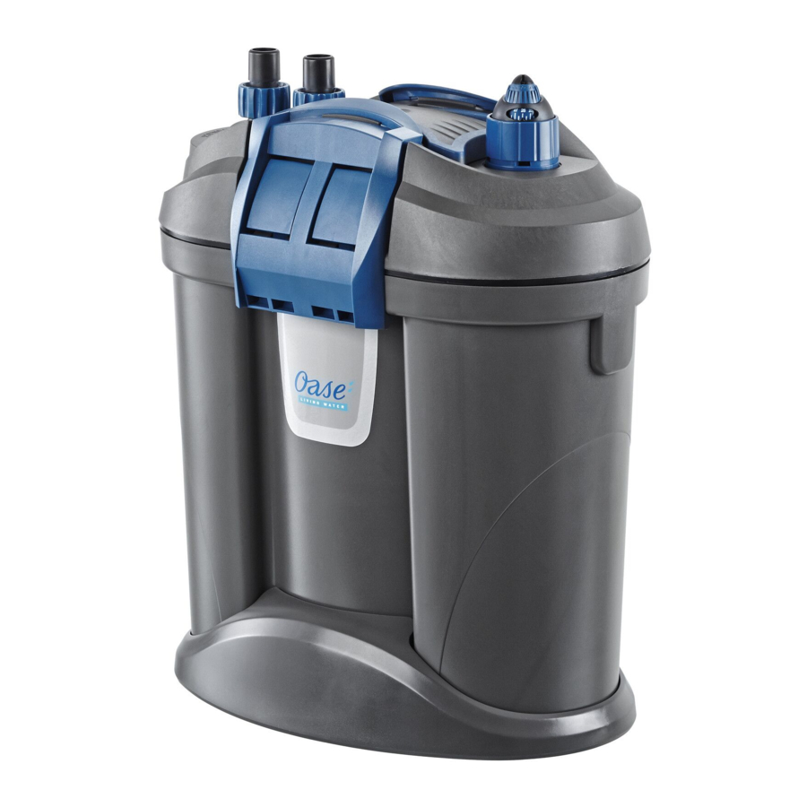
PRODUCT DESCRIPTION
Scope of delivery

| Fig. A | FiltoSmart Thermo |
| 1 | Holding ring with thermo‐control heater HeatUp FiltoSmart Thermo 100: HeatUp 100 FiltoSmart Thermo 200: HeatUp 200 FiltoSmart Thermo 300: HeatUp 300 |
| 2 | Operating manual for thermo‐control heater HeatUp |
FiltoSmart: A blind plug is fitted instead of the thermocontrol heater HeatUp.
| Fig. A | FiltoSmart, FiltoSmart Thermo | Quantity | ||
| 100 | 200 | 300 | ||
| 3 | Operating manual for FiltoS‐mart 100/200/300, FiltoSmart Thermo 100/200/300 | 1 | 1 | 1 |
| 4 | Unit head | 1 | 1 | 1 |
| 5 | Handle, adjustable | — | 1 | 1 |
| 6 | Blind plug | 1 | 1 | 1 |
| 7 | Container, filled with filter media | 1 | 1 | 1 |
| 8 | Foot | 1 | 1 | 1 |
| 9 | Locking clip | 2 | 2 | 2 |
| 10 | Connection unit with hose connector, outlet (OUT) and inlet (IN) | 1 | 1 | 1 |
| B | Connection set | 1 | 1 | 1 |
| 11 | Filter bag with activated carbon | — | 2 | 2 |
| 12 | Ceramic substrate | 1 | 2 | 3 |
| 13 | Bag with 4 feet | 1 | 1 | 1 |
| 14 | Suction pipe | 1 | 1 | 1 |
| 15 | Flow‐out pipe | 1 | 1 | 2 |
| 16 | Short hose section as connecting piece for flow‐out pipes (15) | — | — | 1 |
| 17 | Hose | 1 | 1 | 1 |
| Fig. B | Connection set for FiltoSmart, FiltoSmart Thermo | Quantity | ||
| 100 | 200 | 300 | ||
| 1 | Suction cup | 5 | 5 | 5 |
| 2 | Clamp | 5 | 5 | 5 |
| 3 | Hose adapter, adjustable | 2 | 2 | 2 |
| 4 | Angle piece | 1 | 1 | 1 |
| 5 | Union nut | 4 | 4 | 4 |
| 6 | Adapter, suction pipe FiltoSmart 100 | 1 | — | — |
| 7 | Adapter, suction pipe FiltoSmart 200/300 | — | 1 | 1 |
| 8 | Suction basket FiltoSmart | 1 | 1 | 1 |
| 9 | Cover cap | 1 | 1 | 1 |
| 10 | Water distributor | 1 | 1 | 1 |
Intended use
FiltoSmart 100/200/300, FiltoSmart Thermo 100/200/300, referred to as "unit", may only be used as specified in the following:
- FiltoSmart: Water filtering and recirculation.
- FiltoSmart Thermo: Water heating, filtering and recirculation.
- For operation with freshwater or saltwater.
- Operation under observance of the technical data.
The following restrictions apply to the unit:
- Only use indoors and for aquaristic purposes in the home (not for commercial use).
- Only operate with water at a water temperature of +4°C to +35°C.
Function description
Fig. C

Drawn in by a pump in the unit head, the water flows through two filter chambers arranged next to each other. Then the water flows back into the aquarium via the flow‐out pipe or water distributor. Foam filters with different pore densities, and activated carbon/ceramic substrate serve as filter media. In units with heater, the water is heated during its passage through the filter system.
Retrofitting
FiltoSmart 100/200/300 can be retrofitted with OASE HeatUp (following table).
| FiltoSmart | 100 | 200 | 300 | |
| HeatUp | 25 |  | | |
| 50 | | | | |
| 100 |  | | | |
| 150 | — | | | |
| 200 | – | | | |
| 300 | – | – | |
: Suitable
: Particularly recommended
- 48507 ThermoFit FiltoSmart 100
- 48532 ThermoFit FiltoSmart 200
- 48567 ThermoFit FiltoSmart 300
ACCESSING THE UNIT
 N O T E N O T EThe following applies to all units with heater: |
Careful handling of the heater
 Hot surface! Risk of burns when touching the glass bulb. |
| Risk of breaking the glass! The glass bulb of the heater can break and cause cuts. |
Removing the heater
The heater has to be removed for cleaning and maintenance, and for removing the unit head.
How to proceed:
Fig. D

Fitting the heater
How to proceed:
Fig. E

Removing the connection unit
The heater has to be removed for cleaning and maintenance, and for removing the unit head when hoses are connected.
How to proceed:
Fig. F

- Turn the bayonet closure in the direction "UNLOCK".
- Remove the connection unit.
Fitting the connection unit
How to proceed:
Fig. G

Dismantling the unit head
It has to be removed for cleaning and maintenance and for changing the filter media.
Prerequisite:
- The heater has been removed. (→ Removing the heater)
- The connection unit has been removed. (→ Removing the connection unit)
How to proceed:
Fig. H

- Undo the fasteners.
- Remove the unit head.
Fitting the unit head
How to proceed:
Fig. I

- Ensure that the vent hose is in place and is pointing upwards.
- Fit the unit head onto the container.
- Hinge all fasteners up and lock them in place.
Fitting the retrofit set
| N O T E The following applies to all units with heater: |
Prerequisite
How to proceed:
Fig. K

- Take out a separating plate.
- Remove any residue from the removal of the separating plate.
- Push the stand into the heater tube.
- Fit the heater tube with tube holder into the recess in the bottom of the container.
- Insert the separating plate again.
- Fit the holder and fasten it onto the separating plate (FiltoSmart 200/300) or to the wall of the container (FiltoSmart 100).
- Push the heater into the holding ring as far as it goes.
- To facilitate installation, moisten the glass bulb of the heater with water.
- Do not fit the heater until all work has been completed. (→ Fitting the unit head)
- Ensure that the O ring is correctly positioned.
INSTALLATION AND CONNECTION
Order of tasks to be carried out:
- If the unit is to be installed in a standing position: Fit the enclosed rubber feet onto the base of the container.
- Retrofit the heater unit if necessary (→ Fitting the retrofit set)
- Position the filter media (→ Cleaning/replacing the filter media)
- Install the unit.
Ensure adequate stability
Fig. J

To increase stability, the container is fitted in a stand (removable).
- Screw the enclosed rubber feet into the stand.
- Only install the container with the stand fitted.
Establishing the connections
Assembling the suction unit
How to proceed:
Fig. L

- Assemble the suction unit.
- Set the flow rate.
Assembling the flow‐out unit
How to proceed:
Fig. M

- Assemble the flow‐out unit.
Connecting the hose
The procedure is identical for the inlet (IN) and outlet (OUT).
How to proceed:
Fig. N

- Screw the union nut onto the hose connector of the connection unit.
- Push the hose onto the hose connector and turn the union nut counter‐clockwise to fix the hose in place.
- Push the other end of the hose onto the hose connector at the suction unit/flow‐out unit and turn the union nut counter‐clockwise to fix the hose in place. Fig. C
COMMISSIONING/START‐UP
| N O T E Thoroughly rinse out all filter material with warm tap water before using for the first time in order to remove any soiling. (→ Cleaning/replacing the filter media) |
| N O T E Ensure that the pump never runs dry! The pump will be destroyed. |
| N O T E Risk of fire due to the hot surface of the heater! The heater and filter can be destroyed by the generated heat.
|
How to proceed:
Fig. Q

- Completely fill the container with water and place it next to the aquarium.
- Fill the container via the opening for the heater. For this, remove the heater or blind plug. (→ Removing the heater)
- When starting it up for the first time, ensure that the connection unit is max. 80 cm below the surface of the water. Ensure that the water outlet (flow‐out pipe or water distributor) is not submerged.
- A completely filled filter may be more than 80 cm below the surface of the water. Note the maximum head height. (→ Technical data)
- Unit with heater: Set the water temperature on the heater. (→ Heater operating manual).
Switching on: Connect the unit to the mains. The unit switches on immediately. When the unit is plugged in, it takes several minutes for the air to escape from the unit (this makes a noise). - Adjust the flow at the flow regulator if necessary.
(→ Assembling the suction unit)
Switching off: Disconnect the unit from the mains. - Unit with heater: Disconnect the unit and heater from the power supply
TROUBLESHOOTING
| Malfunction | Cause | Remedy |
| Unit does not start up. | No mains voltage | Check the mains voltage. |
| Impeller unit blocked | Clean | |
| Excessive height difference between the top edge of the aquarium and the suction unit | Reduce the height difference | |
| Water level in the unit too low | Top up water | |
| Water flow insufficient | Filter housing or impeller unit soiled | Clean |
| Impeller unit worn | Replace the impeller unit. | |
| Flow incorrectly set | Correct the setting | |
| Foam filter soiled | Clean | |
| Activated carbon soiled | Clean | |
| Ceramic substrate soiled | Clean | |
| Suction basket clogged | Clean suction basket. | |
| Pipework soiled | Clean suction unit, flow‐out unit and hoses. | |
| Insufficient filtering performance | Foam filter soiled | Clean |
| Foam filter worn | Replace | |
| Ceramic substrate soiled | Clean | |
| Ceramic substrate worn | Replace | |
| Activated carbon exhausted | Replace | |
| Insufficient water heating (only units with heater) | Heater defective | Replace |
| Heater not calibrated | Calibrate | |
| Water temperature incorrectly set on the heater | Correct the water temperature setting on the heater. | |
| Increased noise | Air in the filter, vent hose on the pump not correctly positioned. | Correct the position of the vent hose. |
MAINTENANCE AND CLEANING
- If necessary, clean with clear water using a soft brush.
- Do not use cleaning agents or chemical solutions. We recommend using OASE PumpClean for removing calcium deposits.
- Cleaning and replacement cycles for filter media are dependent on the size of the aquarium and the number of fish. Therefore, it is necessary to clean and replace the filter media as required to ensure optimum filter performance.
- If there are several foam filters: Clean or replace the foam filters at different times. This saves enough useful bacteria to ensure good biological filtration of the water.
Cleaning/replacing the filter media
| N O T E Thoroughly rinse out all filter material with warm tap water before using for the first time in order to remove any soiling. (→ Cleaning/replacing the filter media) |

| Fig. O | Filter media FiltoSmart FiltoSmart Thermo | Quantity | ||
| 100 | 200 | 300 | ||
| a | Foam filter 10 ppi | 1 | 1 | 1 |
| b | Foam filter 20 ppi | — | 1 | 1 |
| c | Ceramic substrate (420 g bag) | 1 | 2 | 3 |
| d | Activated carbon | — | 2 | 2 |
| e | Foam filter 10 ppi | — | 1 | 1 |
Prerequisite
How to proceed:
Fig. P

- Remove the foam filters and rinse in warm water or replace.
- Position the foam filters and activated carbon. The activated carbon has to be taken out of the plastic packaging but remains in its filter bag.
- Rinse the ceramic substrate in warm water or replace.
- FiltoSmart 300 requires three, FiltoSmart 200 two and FiltoSmart 100 one bag (420 g) of ceramic substrate.
- Before using for the first time, remove the ceramic substrate from the plastic bag, rinse it in warm water and put it loosely into the filter container.
- Cover the heater tube, if applicable, when adding the ceramic substrate to ensure that no substrate can enter the heater tube.
Cleaning the heater unit
| N O T E The following applies to all units with heater: |
Fig. D, E
- Unscrew the holding ring and clean the heater according to the separately provided manual or, to replace it, pull it out of the holding ring.
- Reassemble the unit in the reverse order.
Cleaning/replacing the impeller unit
Prerequisite
Fig. R

- Pull the pump lid off downward.
- Reassemble the unit in the reverse order.
Re‐installing the unit
WEAR PARTS
The following components are wear parts and are excluded from the warranty:
- Suction cups
- Impeller unit
- Foam filters
- Activated carbon
- Ceramic substrate
SPARE PARTS
The use of original parts from OASE ensures continued safe and reliable operation of the unit. Please visit our website for spare parts drawings and spare parts.
http://www.oase-livingwater.com/sparepartsinternational-ia

TECHNICAL DATA
| Description | FiltoSmart, FiltoSmart Thermo | ||||
| 100 | 200 | 300 | |||
| Rated voltage | V | 120 | 120 | 120 | |
| Mains frequency | Hz | 60 | 60 | 60 | |
| Protection type | IPX4 | IPX4 | IPX4 | ||
| Power consumption, filter | W | 11 | 17 | 23 | |
| Power consumption, heater | W | 100 | 200 | 300 | |
| Flow rate | Max. | gph | 160 | 210 | 260 |
| Head height | Max. | ft. | 4.6 | 3.3 | 5 |
| Filter volume | gal | 0.34 | 1.1 | 1.7 | |
| Pre‐filter volume | gal | 0.18 | 0.4 | 0.4 | |
| Recommended for an aquarium volume of | Max. | gal | 30 | 55 | 80 |
| Length of power connection cable (also thermo‐control heater) | ft. | 6 | 6 | 6 | |
| Tubing length | ft. | 8 | 8 | 8 | |
| Connection of tubing connectors | Diameter | in. | 1/2 | 2/3 | 2/3 |
| Dimensions | Length | in. | 8 |  | 11 |
| Width | in. | 5.5 | 7 | 7 | |
| Height | in. | 10 | 13.3 | 16.9 | |
| Weight FiltoSmart | lbs | 4.6 | 8.8 | 10 | |
| Weight FiltoSmart Thermo | lbs | 5 | 9.5 | 11 | |
SYMBOLS ON THE UNIT
| IP X4 | Splash-water protected on all sides. |
 | Protection class II, protection insulation which could become live in the event of a fault. |
 | For use indoors. |
 | Do not dispose of with household waste. |
 | Read and adhere to the instructions for use. |
IMPORTANT SAFETY INSTRUCTIONS
READ AND FOLLOW ALL SAFETY INSTRUCTIONS!
Keep these instructions in a safe place.
SAFETY INFORMATION
This unit can be used by children aged 8 and above and by persons with reduced physical, sensory or mental capabilities or lack of experience and knowledge if they are supervised or have been instructed on how to use the unit in a safe way and they understand the hazards involved. Do not allow children to play with the unit. Only allow children to carry out cleaning and user maintenance under supervision. Disconnect the power plug before carrying out any work on the unit.

To guard against injury, basic safety precautions should be observed, including the following:

To avoid possible electric shock, special care should be taken since water is employed in the use of aquarium equipment. For each of the following situations, do not attempt repairs by yourself; return the appliance to an authorized service facility for service or discard the appliance
- Unplug all units in the aquarium and disconnect the power plugs of all units before reaching into the water or moving/cleaning the unit.
![]()
Risk of Electric Shock - Don't use the pump when there are people in the water.![]()
This unit has been evaluated for use with water only.![]()
To reduce the risk of electric shock, use only on portable self-contained fountains.![]()
Never operate the unit if either the electrical cables or the housing are defective!- Do not install or store the appliance where it will be exposed to the weather or to temperatures below freezing.
- Do not carry or pull the unit by its electrical cable.


- If an extension cord is necessary, a cord with a proper rating should be used. A cord rated for less amperes or watts than the appliance rating may overheat. Care should be taken to arrange the cord so that it will not be tripped over or pulled.
- Don't attempt to open the pump/motor enclosure.
- Route cables/hoses such that they are protected from damage and do not present a tripping hazard.
- Only open the unit housing or its attendant components, when this is explicitly required in the operating instructions.
![]()
Only carry out work on the unit that is described in this manual. If problems cannot be overcome, please contact an authorised customer service point or, when in doubt, the manufacturer.- Only use original spare parts and accessories for the unit.
![]()
Never carry out technical modifications to the unit. Don't cut the cord or remove the plug from the cord.- Power connection cables cannot be replaced. If a cable is damaged, dispose of the respective unit or components.
- The impeller unit in the pump contains a magnet with a strong magnetic field that may affect the operation of pacemakers or implantable cardioverter defibrillators (ICDs). Always keep magnets at least 0.7 ft. away from implanted devices.
Electrical connection
- Read and observe all the important notices on the appliance.
- In case of retrofitting, please respect the recommended power, using only OASE HeatUp heaters
- Only connect the unit if the electrical data of the unit and the power supply coincide. The unit data is to be found on the unit type plate, on the packaging or in this manual.
- Protect the plug connections from moisture.
- Only plug the unit into a correctly fitted socket.
- Do have all electrical outlets installed and serviced by a licensed electrician.
![]()
Do disconnect the pump from the electrical outlet at the first sign of any problem.![]()
If the plug or receptacle does get wet, DON'T unplug the cord. Disconnect the fuse or circuit breaker that supplies power to the appliance. Then, unplug and examine for presence of water in the receptacle.![]()
Don't pinch, twist or damage the electrical cord. A minor cut even if only in the outer shell could allow water to reach the motor enclosure and damage the pump. If you notice any damage to the cord remove the pump and store in a dry place. Consult any damage to the electrical cord will void all warranties and could cause serious electrical shock hazard.
- To avoid the possibility of the appliance plug getting wet prevent water from dripping onto plug. A "drip loop," shown in the figure below, should be arranged by the user for each cord connecting an aquarium appliance to a receptacle. The "drip loop" is that part of the cord below the level of the receptacle, or the connector if an extension cord is used, to prevent water traveling along the cord and coming in contact with the receptacle.
![]()

SAVE THESE INSTRUCTIONS!
Symbols used in these instructions
Warnings
The warning information is categorized by signal words, which indicate the extent of the hazard.
NOTE
Information for the purpose of clarification or for pre‐ venting possible damage to assets or to the environment.

Documents / Resources
References
Download manual
Here you can download full pdf version of manual, it may contain additional safety instructions, warranty information, FCC rules, etc.
Thank you! Your question has been received!


Need Assistance?
Do you have a question about the FiltoSmart 100 that isn't answered in the manual? Leave your question here.