Table of Contents
Owner's Manual
®
3.75 HP
17 INCH TmNEWmDTH
FRONT "FINE TILLER
Model No.
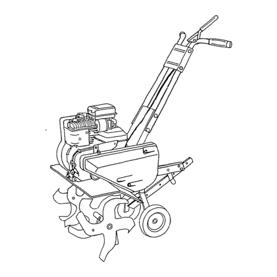
917.292200
o Safety
• Assembly
o Operation
o Maintenance
o Repair Parts
CAUTION:
Read and follow all
Safety Rules and Instructions
before operating this equipment
For answers to your questions
about this product, Call:
1.-800-659=5917
Sears Craftsman Help Line
5 am - 5 pm, Mon - Sat
Sears, Roebuck
and Co,, Hoffman
Estates,
IL 60179
Table of Contents

Related Manuals for Craftsman 3.75 HP 17 INCH TINE WIDTH 917.2922


Summary of Contents for Craftsman 3.75 HP 17 INCH TINE WIDTH 917.2922
- Page 1 Read and follow all Safety Rules and Instructions before operating this equipment Sears, Roebuck and Co,, Hoffman ® For answers to your questions about this product, Call: 1.-800-659=5917 Sears Craftsman Help Line 5 am - 5 pm, Mon - Sat Estates, IL 60179...
- Page 2 • Repairs necessary because of operator shafts and the failure to maintain the equipment tained in the owner's manual o If this Craftsman Tiller is used for commercial applies for only thirty (30) days from the date of purchase. Warranty...
- Page 3 Always refer to the operator's instructions for important tiller is to be stored for an extended _CAUTION: Always plug wire and place wire where it cannot contact spark plug in order to prevent ace dental starting...
- Page 4 Corrtact your nearest Sears store for details. CUSTOMER RESPONSIBILITIES o Read and observe the safety rules.. o Follow a regular schedule ing, cadng for and using your tiller. o Follow the instructions under the "Customer Responsibilities" age" sections of this Owner's...
- Page 5 (2) Hex Bolts 5/16-18 x 1 (2) Hex Bolts 5116-18 x 1-1/4 OPERATOR'S POSITION When right or left hand is mentioned this manual, it means when you are in the operating position behind tiller handles)° Front Left Operator's Position OF HARDWARE PACK G ©...
- Page 6 IMPORTANT:: When uNpacking and as- sembling tiller, be careful not to stretch or kinK cable(s). = Cut cable ties securing handles. o The handle may be assembled in high or low position,,...
- Page 7 KNOWYOURTILLER READTHIS OWNER'SMANUALANDSAFETYRULESBEFOREOPERATING YOUR TILLER, Comparethe illustrations with yourtillerto familiarizeyourselfwith the locationofvari- ous controlsandadjustments.Savethis manualfor future reference. Thesesymbols may appear on your Tiller or in literature supplied with the prod- uct. Learn and understand their meaning. TILLING FORWARD NEUTRAL REVERSE...
- Page 8 The depth stake should always be below the wheels for digging. It serves as a brake to slow the tiller's forward motion to enable the tines to penetrate the ground. Also, the more the depth stake is lowered into the ground the deeper the tines will dig.
- Page 9 • Place throttle control in "FAST' position. • Move choke control to full "CHOKE" position, Grasp recoil starter handle with one hand and grasp tiller handle with other hand Pull rope out slowly until engine reaches start of compression cycle (rope will pull slightly point).
- Page 10 Loose, unpacked soil helps root growth. Best tilling depth is 4" to 6'L A tiller will also clear the soil of unwanted vegeta- tion. The decomposition of this veg- etable matter enriches the soil.
- Page 11 1 - Change more often when operating under a heavy load or In high ambient temperatures 2 - Service more often when operating In dirty or dusly conditions GENERAL RECOMMENDATIONS The warranty on this tiller does not cover items that have been subjected to opera- tor abuse or negligence,,...
- Page 12 Change the oil after every 25 hours of operation or at least once a year if the tiller is not used for 25 hours in one year. Check the crankcase oil level before start- ing the engine and after each five (5) hours of continuous use.
- Page 13 CylinderFins Air Screen MUFFLER Do not operate tiller without muffler. Do not tamper with exhaust system. Damaged mufflers or spark arresters could create a fire hazard. Inspect periodically and re- place if necessary. If your engine is equipped with a spark arrester...
- Page 14 NARROW TILLING/CULT_VATmNG 12-3/4" PATH • Remove outer'tines. Inner Tines Only NARROW CULTIVATING - 12-1/2" PATH ° Remove inner tines, o Assemble holes "A" in tine hubs to holes "C" in tine shaft EDGING - 9-5/8" PATH o Remove inner tines.. •...
- Page 15 CapNutand Cap_ Oe,t uor - Nut _- TO REPLACE V-BELT Replace V-belt if it has stretched consider- ably or if it has cracks or frayed edges. Belt guard must be removed to service bell See "TO REMOVE BELT GUARD" in this section of manual.
- Page 16 Allow the engine to cool before storing in any enclosure, TILLER o Clean entire tiller (See "CLEANING" the Customer Responsibilities section this manual). o Inspect and replace belts, if necessary...
- Page 17 PROBLEM CAUSE Will not start 1, OUt of fuel Engine not"CHOKED" properly & Engine flooded 4_ Dirty air cleaner 5. Water in fuel Clogged fueltank 7. Loose spark plug wire, Bad spark plug or improper gap Carburetor out of adjust- ment Hard to start 1.
- Page 18 1, Ground too wet. Soil balls up or clumps Engine runs but 1. "i3necontrol is not engaged. tiller won't move 2. V-belt not correctly adjusted_ 3_ V-belt is off pulley(s) _t=r 1 Tilling too deep Engine runs but...
- Page 19 REPAIR PARTS TILLER - - MODEL NUMBER HANDLE ASSEMBLY PART DESCRIPTION 137176X574 Bracket, Handle 72140512 "Bolt,Carriage 5/16-18 UNC x 1-l/2 73680500 "Lecknut, Crown 5/16-18 19111116 "Washer 11/32 x 11/16 x 16 Ga 151473 Handle, LH 9266R Gdp, Handle 74760524 "Bolt,Hex 5/16-18 x 1-1/2...
- Page 20 REPAIR PARTS TILLER - - MODEL NUMBER BELT GUARD AND PULLEY ASSEMBLY PART DESCRIPTION 23230506 *Screw, Set, Forged Socket, Headless 5/16-18 x 3/8 130811 Pulley, Engine 122965X Bracket Assembly, Guard, Belt 72140404 *Bolt, Carriage 1/4-20 x 1/2 74610812 Bolt, Hex 1/2-20 x 3/4...
- Page 21 REPAIR PARTS TILLER - - MODEL NUMBER WHEEL AND DEPTH STAKE ASSEMBLY 1716__ KEY PART DESCRIPTION 74760520 *Dolt, Hex 5/16-18 x 1-1/4 73220500 *Nut, Hex 5/16-18 10040500 *Washer, Lock 5/16 19121414 *Washer 3/8 x 7/8 x 14 Ga 4921H Clip, Hairpin...
- Page 22 REPAIR PARTS TILLER - - MODEL NUMBER TINE ASSEMBLY DESCRIPTION PART Tine, Outer, R H 106860X 4921H Clip, Hairpin line, Inner, RH 106858X 917,292200 PART DESCRIPTION 106857X Tine, Inner, L H 106859X Tine, Outer, L H 9194R Pin, Clevis...
- Page 23 REPAIR PARTS TILLER - - MODEL NUMBER TRANSMISSION KEY PART DESCRIPTION 74610412 Bolt, Hex 1/4-28 x 3/4 Gr 5 10040400 • Washer, Lock 1/4 19092016 Washer 9/32 x 1-1/4 x 16 Ga 19091412 Washer 9/32 x 7/8 x 12 Ga 74760544 "...
- Page 24 273873 163516 163517 917.292200 DESCRIPTION Decal, Logo Decal, Logo Decal, Oper/Lubrication Decal, Tine Control Decal, Hand Placement Decal, ]]ne Shield Wrng Dorn Decal, Warning, Rotating ]qnes Decal, Craftsman Decal, Control Speed Decal, 3.75 HP Manual, Owner's (English) Manual, Owner's (Spanish)
- Page 25 REPAIR PARTS TILLER - - MODEL NUMBER 917.292200 BRIGGS & STRATTON ENGINE -- MODEL NUMBER 94202, TYPE NO,01115-E1 INSTRUCTION MANUAL...
- Page 26 REPAIR PARTS TILLER - - MODEL NUMBER 917.292200 BRIGGS & STRATTON ENGINE -- MODEL NUMBER 94202, TYPE NO.O1115-E1 _363 124_ • 305 _P...
- Page 27 REPAnRPARTS TILLER - - MODEL NUMBER BRIGGS & STRATTON ENGINE -- MODEL 190A_ 917.292200 NUMBER 94202, TYPE NO.01115-E1 1019 LABEL KIT ] REQUIRES SPECIALTOOLS TO INSTALL. SEE REPAIR INSTRUCTION MANUAL...
- Page 28 REPAIR PARTS TILLER - - MODEL NUMBER BRIGGS & STRATTON ENGINE -- MODEL NUMBER 94202, TYPE NO.01115-E1 PART DESCRIPTION 494549 Cylinder Assembly 293708 Bushing, Cylrhder (Special Tools Required For Installation) 299819 " Seal, Oi_ 214277 Head, Cylinder 272694 -" Gasket, Cylinder Head...
- Page 29 REPAIR PARTS TILLER - - MODEL NUMBER BRIGGS & STRATTON ENGINE -- MODEL NUMBER 94202, TYPE NO.01115-E1 PART DESCRIPTION 495213 Blade, Governor 263174 Link, Governor 262470 Link, Throttle 260041 Spdng, Governor 263188 Link, Choke 499533 Bracket, Control 93543 Screw, Hex Head...
- Page 32 =orthe repair or replacement parts you need :lelivered directly to your home 3all 7 am - 7 pm, 7 days a week 1-800=366-PART I1-800-366-7278) Para ordenar piezas con entrega domicilio - 1-800-659-7084 For in-house major brand repair service 3all 24 hours a day, 7 days a week 1=800=4-REPAIR (1-800-473-7274) Para pedir servicio de reparacibn...