Table of Contents
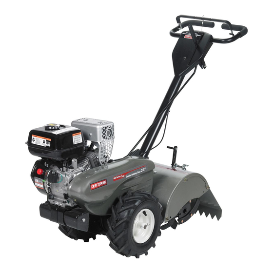
Owner's Manual
CRRFT$14RH °
TI ETLL
COU TE
ROTATI
900 Series
14 Inch Tine Width
G
IT
T
Model No.
917.299060
\
• EspaSol,
p. 22
This product has a low emission
engine which operates
differently
from previously
built engines.
Before
you start the
engine,
read and understand
this Owner's
Manual.
IMPORTANT:
Read and follow all Safety
Rules and Instructions
before
operating
this equipment.
Sears, Roebuck
and Co., Hoffman
Estates, IL 60179
Visit our Craftsman
website:www.sears.com/craftsman
U.S.A.
423763 Rev. 1
Table of Contents

Related Manuals for Craftsman 29906 - 14 in. Rear Tine Tiller

Summary of Contents for Craftsman 29906 - 14 in. Rear Tine Tiller
- Page 1 Before you start the engine, read and understand this Owner's Manual. IMPORTANT: Read and follow all Safety Rules and Instructions before operating this equipment. U.S.A. Sears, Roebuck and Co., Hoffman Estates, IL 60179 Visit our Craftsman website:www.sears.com/craftsman 423763 Rev. 1...
- Page 2 • If this Craftsman Tiller is used for commercial or rental purposes, this Warranty plies for only thirty (30) days from the date of purchase. Warranty...
- Page 3 • Use extension cords and receptacles • Never operate the machine at high as specified by the manufacturer for all speeds on slippery surfaces. Look be- units with electric drive motors or elec- hind and use care when backing. tric starting motors.
- Page 4 AGREEMENTS of a Sears Tiller. It has been designed, Congratulations on making a smart pur- engineered and manufactured to give you chase. Your new Craftsman@ product the best possible dependability and per- formance. designed and manufactured for years of dependable operation.
- Page 5 These accessories were available when the tiller was produced. They are also available at most Sears retail outlets and service centers. Some of these accessories may not apply to your tiller. ENGINE SPARK PLUG MUFFLER AiR FILTER GAS CAN ENGINE OiL STABiLiZER TILLER PERFORMANCE FURROW OPENER...
- Page 6 Your new tiller has been assembled at the factory with the exception of those parts left unassembled for shipping purposes. To ensure safe and proper operation of your tiller all parts and hardware you assemble must be tightened securely. Use the correct tools as necessary to insure...
- Page 7 Handle Column Cables Cable Clip Loosen Handle Lock handles Lever to Move CONNECT SHIFT Insert end of shift rod farthest from bend into hole of shift lever indicator. Insert hairpin dip through hole of shift rod to secure with bend of clip on right Insert pivot bolt in front part of plate...
- Page 8 These symbols may appear on your Tiller or in literature supplied with the product, Learn and understandtheir meaning, KNOW YOUR TILLER READ THIS OWNER'S MANUAL AND SAFETY RULES BEFORE OPERATING YOUR TILLER. Compare the illustrations with your tiller to familiarize yourself with the location various...
- Page 9 The operation of any tiller can result in foreign objects thrown into the eyes, which can result in severe eye damage. Always wear safety glasses or eye shields before starting your tiller and while tilling. We recommend a wide vi- sion safety mask over spectacles...
- Page 10 AROUND TOWN Hold the drive control bar against handle to start tilling movement. Tines Disconnect spark plug wire. and wheels will both turn. Drain fuel tank. Move throttle control to "FAST" position Transport in upright position to prevent for deep tilling. To cultivate, throttle oil leakage.
- Page 11 Fuel Valve _iILCAUTION: Fill to within 1/2 inch of top Spark of fuel tank to prevent spills and to allow for fuel expansion. If gasoline is acciden- Throttle tally spilled, move machine away from area of spill. Avoid creating any source ignition until gasoline vapors...
- Page 12 ADJUST WHEELS CULTIVATING Place blocks under right hand side of tiller and remove hairpin clip and clevis pin from right hand wheel. Move wheel outward approximately inch until hole in inner wheel hub lines up with inner hole in axle. Replace clevis pin and hairpin...
- Page 13 / / / / / MAINTENANCE SERVICE DATES REGULAR SERVICE _'_'_'_ _'_'_"_'x M Check Engine 0il Level Change Engine Oil _1,2 Oil Pivot Points V _' Inspect Spark Arrester / Muffler Inspect Air Screen Clean or Replace Air Cleaner Cartridge Clean Engine Cylinder Fins Replace Spark Plug 1 - Change more often when operating under a heavy load or in high ambient temperatures.
- Page 14 Refill engine with oil. See "CHECK _L, CAUTION: Disconnect spark plug ENGINE OIL LEVEE' in the Operation wire before performing any maintenance section of this manual. (except carburetor adjustment) to prevent accidental starting of engine. Prevent fires! Keep the engine free of grass, leaves, spilled oil, or fuel.
- Page 15 COOLING SYSTEM SPARK PLUG Your engine is air cooled. For proper Replace spark plugs at the beginning gine performance and long life keep your each tilling season or after every 25 hours engine clean. of use, whichever comes first. Spark plug •...
- Page 16 TIRE CARE Belt Guard _ILCAUTION: When mounting tires, less beads are seated, ovednflation Washer cause an explosion. (Located • Maintain 20 pounds of tire pressure. Behind tire pressures are not equal, tiller will Tire) pull to one side. Screws • Keep tires free of gasoline or oil which can damage rubber.
- Page 17 TINE REPLACEMENT • To maintain the superb tilling perfor- mance of this machine the tines should J_,CAUTION: Tines are sharp. Wear be checked for sharpness, wear, and gloves or other protection when handling bending, particularly the tines which tines. are next to the transmission. If the gap A badly worn tine causes...
- Page 18 ENGINE TO ADJUST CARBURETOR Maintenance, repair, or replacement The carburetor has been preset at the the emission control devices and systems, factory and adjustment should not be which are being done at the customers necessary. However, engine performance pense, may be performed by any non-road can be affected by differences...
- Page 19 Immediately prepare your tiller for storage NOTE: Fuel stabilizer is an acceptable at the end of the season or if the unit will alternative in minimizing the formation not be used for 30 days or more. fuel gum deposits during storage.
- Page 20 TROUBLESHOOTING CHART: See appropriate section in manual unless directed to Sears service center PROBLEM CAUSE CORRECTION Will not start Out of fuel. Fill fuel tank. Fuel valve "OFF" Turn fuel valve to the "ON" position. Engine Switch "OFF" Turn engine switch to the "ON" position. Engine not "CHOKED"...
- Page 21 TROUBLESHOOTING CHART: See appropriate section in manual unless directed to Sears service center PROBLEM CAUSE CORRECTION Excessive Ground too dry and hard. Moisten ground or wait for more favorable soil conditions bounce/ difficult Wheels and depth stake Adjust wheels and depth stake. handling incorrectly adjusted.
- Page 22 • Si la Cultivadora Craftsman se usa para fines de arriendo, esta garanfia se aplica solamente treinta (30) treintadias a partir de la fecha de compra. El Servicio de Garantia esta disponible al devolver la cultivadora Craftsman al centro/departamento de servicio Sears mas cercano en los estados unidos.
- Page 23 MANTENIMIENTO Y ALMACENAIVIIENTO • Despues de pegarle a un objeto extraflo, pare el motor, remueva el alambre de la • Mantenga los accesorios y aditamentos bujia, inspeccione la cultivadora cuidadosa- la maquina en buenas condiciones para el funcionamiento. mente, para verificar si hay daflos, y repare el daflo antes de volver a arrancar y operar •...
- Page 24 LA REPARACION Capacidad de gasotina: 3 Cuartos (2.8L) Congratulaciones por su buena compra. Sin ptomo, regular Su nuevo producto Craftsman® est& diseSado y fabricado para funcionar de modo fiable por Aceite (API-SG-SL): SAE 30 (Sobre 32°F) (Capacidad:20 oz./0.6L) SAE 5W-30 muchos aSos.
- Page 25 Estos accesorios estaban disponibles cuando se produjo la cultivadora. Tambien est&n disponibles en la mayoria de las tiendas de Sears yen los centros de servicio. Algunos de estos accesorios tal vez no se apliquen a su cultivadora. MOTOR BUJ|A SILENCIADOR FILTRO DE AIRE LATA DE GASOLINA ACEITE...
- Page 26 Su cultivadora nueva ha sido montada en la f&brica, con la excepci6n de aquellas partes que se dejaron sin montar por razones de envio. Para asegurarse que la cultivadora operara en forma segura y adecuada, todas las partes y los articulos de ferreteria que monte tienen que estar apre- tados en forma segura.
- Page 27 Conjunto det mango Cotumna det posoci6n 'Arriba" Mango Cables Abrazadera del Suette la patanca de Cable cierre del mango para moverla CONEXION DE LA VARILLA DE CAMBIO Inserte el extremo de la varilla de cambio que est& mgts alejado de la dobladura, el agujero del indicador de la palanca de cambio.
- Page 28 Estos simbolos pueden apareser sobre su cultivadora en la literature proporcionada con el pro- ducto, aprenda y comprenda sus significados. CONOZCA SU CULTIVADORA LEA ESTE MANUAL DEL DUENO Y LAS REGLAS DE SEGURIDAD ANTES DE OPERAR SU CULTWADORA Compare las ilustraciones con su cultivadora para familiarizarse con la ubicaci6n...
- Page 29 La operaci6n de cualquier cultivadora puede hacer que salten objetos extraflos dentro de sus ojos, Io que puede producir daflos graves en estos. Siempre use anteojos de seguridad o protecciones para los ojos antes de hacer arrancar su cultivadora o mientras este labrando con ella.
- Page 30 3. Sujetelabarrade control d ela impulsi6n Sujete la barra de control de la impulsi6n en contradelmangoparaempezar c onel en contra del mango para empezar con el movimiento d e labraci6n. Tanto losbrazos movimiento de la cultivadora. Los brazos no comolasruedas vana girar. van a girar.
- Page 31 AGREGUE GASOLINA Mueve la palanca del regulador lejos • Llene el estanque de combustible. Llene de la posici6n ,,SLOW>, (lento), aproxi- hasta la parte inferior del cuello de rel- madamente 1/3 de vuelta hacia leno del estanque de gasolina. No Io Ilene posici6n ,,FAST>, (r_.pido).
- Page 32 CONSEJOS PARA LABRAR _PRECAUCl6N:Antes de acostumbrarse S°%. manejar su cultivadora, empiece el uso de esta \/F_ en el terreno con la aceleraci6n en la posici6n 7-'% /--'_ (7.? de "lento" (SLOW). • El labrar quiere decir el excavar, dar vuelta y romper el suelo duro antes de plantar.
- Page 33 PROGRAMA Zo// MANTENIMIENTO LLENE LAS FECHAS DE MEDIDA /_'/_"bOi%_?< SERVIClO REGULAR FECHAS DE SERVlCIO Revisar et nivet del aceite del motor Cambiar el aceite del motor Aceitar los puntos de pivote Inspeccionar et supresor del sitenciador Inspeccionar la rejitta de aire Limpiar/cambiar et cartucho del fittro de aire Limpiar las aletas del citindro del motor L.,-.,-.,.-...
- Page 34 Despues de que el aceite se haya drenado _L',PRECAUCl0N: Desconecte e! alambre de completamente, vuelva a colocar el tap6n la bujia antes de dar mantenimiento (excepto del drenaje del aceite y aprietelo en forma pot el ajuste del carburador) para evitar que el segura.
- Page 35 EL SISTEMA DE ENFRIAMIENTO LAS BUJiAS Este motor es un motor enfriado por aire. Para Reemplace las bujias al comienzo de la obtener un rendimiento adecuado del motor temporada de arado o despues de cada y una mayor vida Otil, mantengalo limpio.
- Page 36 CUIDADO DE LAS LLANTAS Protecci6n de la correa ,_PRECAUCI6N: Cuando monte las Ilantas, Tuerca a menos que los talones esten asentados, si Hexagonal se inflan demasiado se puede producir una y arandeta explosi6n. (Ubicadas • Mantenga 20 libras de presi6n en las Ilantas. detras de la Si la presi6n de las Ilantas no es la misma, la Ilanta)
- Page 37 CAMBIO DE BRAZOS • Para que esta m&quina pueda mantener un rendimiento excelente en el labrado, se _I_,PRECAUCl6N: Los brazos son afilados. deben revisar los brazos para verificar si Use guantes u otra protecci6n cuando maneje est&n afilados, desgastados o doblados, los brazos.
- Page 38 PARA AJUSTAR EL CARBURADOR EL MOTOR El carburador tiene un chorro de alta velocidad El mantenimiento, la reparaci6n o el y ha sido preajustado en la f&brica y no deberia reemplazo de los sistemas y dispositivos necesitar ajustes. Sin embargo, se pueden de control de emisi6n, Io cual se realiza...
- Page 39 AVlSO: El estabilizador de combustible es una Inmediatamente prepare su cultivadora para el almacenamiento al final de la temporada o si la alternativa aceptable para reducir a un minimo unidad no se va a usar por 30 dias o mas. la formaci6n de dep6sitos de goma en el com- bustible durante el periodo de almacenamiento.
- Page 40 IDENTIFICACION DE PROBLEMAS: Yea la secci6n apropiada en el manual a menos que este dirigido a un centro de servicio Sears. CORRECCION PROBLEMA CAUSA No arranca Se acab6 el combustible. Llene el tanque de combustible. La v&tvuta de combustible est& en Gire ta v&tvuta de combustible hasta la la posici6n -OFF,, (apagado) posici6n-ON>,...
- Page 41 IDENTIFICACION DE PROBLEMAS: Yea la secci6n apropiada en el manual a menos que este dirigido a un centro de servicio Sears. CORRECCION PROBLEMA CAUSA Controte el nivel de aceite/cambie el aceite. El motor El nivet de aceite esta bajo/el recalienta aceJte esta sucio.
- Page 42 TILLER - - MODEL NUMBER 917.299060 HANDLES KEY PART PART DESCRIPTION DESCRIPTION 141406 STD541437 Nut, Crowntock 3/8-16 Grip, Handle 110673X Grommet, Handle 19131611 Washer 13/32xlx11 127254X 109228X Lever, Lock, Handle Bar, Drive Control Assembly 6712J 420524 Handle, Assemble Cap, Vinyl 189347 Panel, Control 165197...
- Page 43 TILLER - - MODEL NUMBER 917.299060 MAINFRAME, LEFT SIDE mainflame left KEY PART PART DESCRIPTION DESCRIPTION STD541037 Nut, Hex 3/8-16 132801 Belt, V 432420 Shield, Inner Belt Guard 104679X Pulley, Idler 164329 Pin Spiral Flared 12000032 Ring, Klip 110111× Lever, Shift 159229 Bracket, Idler STD532505...
- Page 44 TILLER - - MODEL NUMBER 917.299060 MAINFRAME, RIGHT SiDE main frame_rig ht_LCT_3 KEY PART PART DESCRiPTiON DESCRIPTION 73970500 Locknut, He×, Flange 5/16-18 Engine, (See Breakdown) 102332× LOT Model No. Bracket, Reinforcement 102173× PLM HK14600124P-BPQE2 Counter Weight, R.H. 74760524 73510600 Bolt, Hex 5/16-18 x 1-1/2 Nut Keps Hex 3/8-16 unc 4497H Retainer, Spring...
- Page 45 TILLER - - MODEL NUMBER 917.299060 TRANSMISSION transmission 19.5b KEY PART PART DESCRIPTION DESCRIPTION 188554 Transmission Assembly (Includes 150737 Ground Shaft Assembly Key Nos. 2-52) 143008 Bearing, Shaft, Ground Drive R.H. 188482 Gearcase, L.H. w/Bearing 106388X Spacer 0.70 x 1.00 x 1.150 (Includes Key No.
- Page 46 TILLER - - MODEL NUMBER 917.299060 TINE SHIELD 27 i tine shield 14 in rl PART PART DESCRIPTION DESCRIPTION 73900500 Nut, Lock Hex Fig 5/16-18 unc 102156X Stake, Depth 74930632 Bolt, Hex 3/8-16 x 2 8393J Pin, Stake, Depth 12000035 Ring, Klip 4440J Hinge...
- Page 47 TILLER - - MODEL NUMBER 917.299060 TINE ASSEMBLY tine_ipb_99_2 PART PART DESCRIPTION DESCRIPTION 4459J Tine, Outer, LH. 4460J Tine, Outer, R.H. 132673 Pin, Shear 132722 Assembly, Hub and Plate, R.H. 6554J Tine, Inner, L.H. 6555J Tine, Inner, R.H. 3146R Clip, Hairpin 132721 Assembly, Hub and Plate, L.H.
- Page 48 TILLER - - MODEL NUMBER 917.299060 DECALS PART DESCRIPTION 425263 Decal, Bit Guard 425264 Decal, Description 137538 Decal, Caution, Drive Control 120431× Decal, Hand Placement 102180× Decal, Shift Indicator 419743 Decal, Console 120075× Decal, Warning, Rotating Tines 163094 Decal, Tine Depth Stake 162215 Decal, Tine, Shield, Warning Dom 423884...
- Page 49 TILLER - - MODEL NUMBER 917. 299080 ENGINE, LCT -- MODEL NUMBER PLMHK14600124P-BPQE2 208cc SERVICE KIT BREAKDOWN PART PART DESCRIPTION DESCRIPTION 420578 Cylinder Head Service Kit Sk208-1000 420595 ignition Coil Service Kit Sk208-2500 420579 Push Rod Service Kit Sk208-1001 420596 Ignition Module Service Kit Sk2750 420580 Valve Cover Service Kit Sk4500...
- Page 52 NEED MORE HELP? You_[ find the ar_swer and mo_e oi_ _anagemyhomeoCOm _ for free! o Find this and aLLyour other )roduct manuals online. o Get answers from our team of home experts. o Get a personalized maintenance plan for your home. o Find information and tools to help with home projects.
- Page 53 Before you start the engine, read and understand this Owner's Manual. IMPORTANT: Read and follow all Safety Rules and Instructions before operating this equipment. U.S.A. Sears, Roebuck and Co., Hoffman Estates, IL 60179 Visit our Craftsman website:www.sears.com/craftsman 423763 Rev. 1...
- Page 54 • If this Craftsman Tiller is used for commercial or rental purposes, this Warranty plies for only thirty (30) days from the date of purchase. Warranty...
- Page 55 • Use extension cords and receptacles • Never operate the machine at high as specified by the manufacturer for all speeds on slippery surfaces. Look be- units with electric drive motors or elec- hind and use care when backing. tric starting motors.
- Page 56 AGREEMENTS of a Sears Tiller. It has been designed, Congratulations on making a smart pur- engineered and manufactured to give you chase. Your new Craftsman@ product the best possible dependability and per- formance. designed and manufactured for years of dependable operation.
- Page 57 These accessories were available when the tiller was produced. They are also available at most Sears retail outlets and service centers. Some of these accessories may not apply to your tiller. ENGINE SPARK PLUG MUFFLER AiR FILTER GAS CAN ENGINE OiL STABiLiZER TILLER PERFORMANCE FURROW OPENER...
- Page 58 Your new tiller has been assembled at the factory with the exception of those parts left unassembled for shipping purposes. To ensure safe and proper operation of your tiller all parts and hardware you assemble must be tightened securely. Use the correct tools as necessary to insure...
- Page 59 Handle Column Cables Cable Clip Loosen Handle Lock handles Lever to Move CONNECT SHIFT Insert end of shift rod farthest from bend into hole of shift lever indicator. Insert hairpin dip through hole of shift rod to secure with bend of clip on right Insert pivot bolt in front part of plate...
- Page 60 These symbols may appear on your Tiller or in literature supplied with the product, Learn and understandtheir meaning, KNOW YOUR TILLER READ THIS OWNER'S MANUAL AND SAFETY RULES BEFORE OPERATING YOUR TILLER. Compare the illustrations with your tiller to familiarize yourself with the location various...
- Page 61 The operation of any tiller can result in foreign objects thrown into the eyes, which can result in severe eye damage. Always wear safety glasses or eye shields before starting your tiller and while tilling. We recommend a wide vi- sion safety mask over spectacles...
- Page 62 AROUND TOWN Hold the drive control bar against handle to start tilling movement. Tines Disconnect spark plug wire. and wheels will both turn. Drain fuel tank. Move throttle control to "FAST" position Transport in upright position to prevent for deep tilling. To cultivate, throttle oil leakage.
- Page 63 Fuel Valve _iILCAUTION: Fill to within 1/2 inch of top Spark of fuel tank to prevent spills and to allow for fuel expansion. If gasoline is acciden- Throttle tally spilled, move machine away from area of spill. Avoid creating any source ignition until gasoline vapors...
- Page 64 ADJUST WHEELS CULTIVATING Place blocks under right hand side of tiller and remove hairpin clip and clevis pin from right hand wheel. Move wheel outward approximately inch until hole in inner wheel hub lines up with inner hole in axle. Replace clevis pin and hairpin...
- Page 65 / / / / / MAINTENANCE SERVICE DATES REGULAR SERVICE _'_'_'_ _'_'_"_'x M Check Engine 0il Level Change Engine Oil _1,2 Oil Pivot Points V _' Inspect Spark Arrester / Muffler Inspect Air Screen Clean or Replace Air Cleaner Cartridge Clean Engine Cylinder Fins Replace Spark Plug 1 - Change more often when operating under a heavy load or in high ambient temperatures.
- Page 66 Refill engine with oil. See "CHECK _L, CAUTION: Disconnect spark plug ENGINE OIL LEVEE' in the Operation wire before performing any maintenance section of this manual. (except carburetor adjustment) to prevent accidental starting of engine. Prevent fires! Keep the engine free of grass, leaves, spilled oil, or fuel.
- Page 67 COOLING SYSTEM SPARK PLUG Your engine is air cooled. For proper Replace spark plugs at the beginning gine performance and long life keep your each tilling season or after every 25 hours engine clean. of use, whichever comes first. Spark plug •...
- Page 68 TIRE CARE Belt Guard _ILCAUTION: When mounting tires, less beads are seated, ovednflation Washer cause an explosion. (Located • Maintain 20 pounds of tire pressure. Behind tire pressures are not equal, tiller will Tire) pull to one side. Screws • Keep tires free of gasoline or oil which can damage rubber.
- Page 69 TINE REPLACEMENT • To maintain the superb tilling perfor- mance of this machine the tines should J_,CAUTION: Tines are sharp. Wear be checked for sharpness, wear, and gloves or other protection when handling bending, particularly the tines which tines. are next to the transmission. If the gap A badly worn tine causes...
- Page 70 ENGINE TO ADJUST CARBURETOR Maintenance, repair, or replacement The carburetor has been preset at the the emission control devices and systems, factory and adjustment should not be which are being done at the customers necessary. However, engine performance pense, may be performed by any non-road can be affected by differences...
- Page 71 Immediately prepare your tiller for storage NOTE: Fuel stabilizer is an acceptable at the end of the season or if the unit will alternative in minimizing the formation not be used for 30 days or more. fuel gum deposits during storage.
- Page 72 TROUBLESHOOTING CHART: See appropriate section in manual unless directed to Sears service center PROBLEM CAUSE CORRECTION Will not start Out of fuel. Fill fuel tank. Fuel valve "OFF" Turn fuel valve to the "ON" position. Engine Switch "OFF" Turn engine switch to the "ON" position. Engine not "CHOKED"...
- Page 73 TROUBLESHOOTING CHART: See appropriate section in manual unless directed to Sears service center PROBLEM CAUSE CORRECTION Excessive Ground too dry and hard. Moisten ground or wait for more favorable soil conditions bounce/ difficult Wheels and depth stake Adjust wheels and depth stake. handling incorrectly adjusted.
- Page 74 • Si la Cultivadora Craftsman se usa para fines de arriendo, esta garanfia se aplica solamente treinta (30) treintadias a partir de la fecha de compra. El Servicio de Garantia esta disponible al devolver la cultivadora Craftsman al centro/departamento de servicio Sears mas cercano en los estados unidos.
- Page 75 MANTENIMIENTO Y ALMACENAIVIIENTO • Despues de pegarle a un objeto extraflo, pare el motor, remueva el alambre de la • Mantenga los accesorios y aditamentos bujia, inspeccione la cultivadora cuidadosa- la maquina en buenas condiciones para el funcionamiento. mente, para verificar si hay daflos, y repare el daflo antes de volver a arrancar y operar •...
- Page 76 LA REPARACION Capacidad de gasotina: 3 Cuartos (2.8L) Congratulaciones por su buena compra. Sin ptomo, regular Su nuevo producto Craftsman® est& diseSado y fabricado para funcionar de modo fiable por Aceite (API-SG-SL): SAE 30 (Sobre 32°F) (Capacidad:20 oz./0.6L) SAE 5W-30 muchos aSos.
- Page 77 Estos accesorios estaban disponibles cuando se produjo la cultivadora. Tambien est&n disponibles en la mayoria de las tiendas de Sears yen los centros de servicio. Algunos de estos accesorios tal vez no se apliquen a su cultivadora. MOTOR BUJ|A SILENCIADOR FILTRO DE AIRE LATA DE GASOLINA ACEITE...
- Page 78 Su cultivadora nueva ha sido montada en la f&brica, con la excepci6n de aquellas partes que se dejaron sin montar por razones de envio. Para asegurarse que la cultivadora operara en forma segura y adecuada, todas las partes y los articulos de ferreteria que monte tienen que estar apre- tados en forma segura.
- Page 79 Conjunto det mango Cotumna det posoci6n 'Arriba" Mango Cables Abrazadera del Suette la patanca de Cable cierre del mango para moverla CONEXION DE LA VARILLA DE CAMBIO Inserte el extremo de la varilla de cambio que est& mgts alejado de la dobladura, el agujero del indicador de la palanca de cambio.
- Page 80 Estos simbolos pueden apareser sobre su cultivadora en la literature proporcionada con el pro- ducto, aprenda y comprenda sus significados. CONOZCA SU CULTIVADORA LEA ESTE MANUAL DEL DUENO Y LAS REGLAS DE SEGURIDAD ANTES DE OPERAR SU CULTWADORA Compare las ilustraciones con su cultivadora para familiarizarse con la ubicaci6n...
- Page 81 La operaci6n de cualquier cultivadora puede hacer que salten objetos extraflos dentro de sus ojos, Io que puede producir daflos graves en estos. Siempre use anteojos de seguridad o protecciones para los ojos antes de hacer arrancar su cultivadora o mientras este labrando con ella.
- Page 82 3. Sujetelabarrade control d ela impulsi6n Sujete la barra de control de la impulsi6n en contradelmangoparaempezar c onel en contra del mango para empezar con el movimiento d e labraci6n. Tanto losbrazos movimiento de la cultivadora. Los brazos no comolasruedas vana girar. van a girar.
- Page 83 AGREGUE GASOLINA Mueve la palanca del regulador lejos • Llene el estanque de combustible. Llene de la posici6n ,,SLOW>, (lento), aproxi- hasta la parte inferior del cuello de rel- madamente 1/3 de vuelta hacia leno del estanque de gasolina. No Io Ilene posici6n ,,FAST>, (r_.pido).
- Page 84 CONSEJOS PARA LABRAR _PRECAUCl6N:Antes de acostumbrarse S°%. manejar su cultivadora, empiece el uso de esta \/F_ en el terreno con la aceleraci6n en la posici6n 7-'% /--'_ (7.? de "lento" (SLOW). • El labrar quiere decir el excavar, dar vuelta y romper el suelo duro antes de plantar.
- Page 85 PROGRAMA Zo// MANTENIMIENTO LLENE LAS FECHAS DE MEDIDA /_'/_"bOi%_?< SERVIClO REGULAR FECHAS DE SERVlCIO Revisar et nivet del aceite del motor Cambiar el aceite del motor Aceitar los puntos de pivote Inspeccionar et supresor del sitenciador Inspeccionar la rejitta de aire Limpiar/cambiar et cartucho del fittro de aire Limpiar las aletas del citindro del motor L.,-.,-.,.-...
- Page 86 Despues de que el aceite se haya drenado _L',PRECAUCl0N: Desconecte e! alambre de completamente, vuelva a colocar el tap6n la bujia antes de dar mantenimiento (excepto del drenaje del aceite y aprietelo en forma pot el ajuste del carburador) para evitar que el segura.
- Page 87 EL SISTEMA DE ENFRIAMIENTO LAS BUJiAS Este motor es un motor enfriado por aire. Para Reemplace las bujias al comienzo de la obtener un rendimiento adecuado del motor temporada de arado o despues de cada y una mayor vida Otil, mantengalo limpio.
- Page 88 CUIDADO DE LAS LLANTAS Protecci6n de la correa ,_PRECAUCI6N: Cuando monte las Ilantas, Tuerca a menos que los talones esten asentados, si Hexagonal se inflan demasiado se puede producir una y arandeta explosi6n. (Ubicadas • Mantenga 20 libras de presi6n en las Ilantas. detras de la Si la presi6n de las Ilantas no es la misma, la Ilanta)
- Page 89 CAMBIO DE BRAZOS • Para que esta m&quina pueda mantener un rendimiento excelente en el labrado, se _I_,PRECAUCl6N: Los brazos son afilados. deben revisar los brazos para verificar si Use guantes u otra protecci6n cuando maneje est&n afilados, desgastados o doblados, los brazos.
- Page 90 PARA AJUSTAR EL CARBURADOR EL MOTOR El carburador tiene un chorro de alta velocidad El mantenimiento, la reparaci6n o el y ha sido preajustado en la f&brica y no deberia reemplazo de los sistemas y dispositivos necesitar ajustes. Sin embargo, se pueden de control de emisi6n, Io cual se realiza...
- Page 91 AVlSO: El estabilizador de combustible es una Inmediatamente prepare su cultivadora para el almacenamiento al final de la temporada o si la alternativa aceptable para reducir a un minimo unidad no se va a usar por 30 dias o mas. la formaci6n de dep6sitos de goma en el com- bustible durante el periodo de almacenamiento.
- Page 92 IDENTIFICACION DE PROBLEMAS: Yea la secci6n apropiada en el manual a menos que este dirigido a un centro de servicio Sears. CORRECCION PROBLEMA CAUSA No arranca Se acab6 el combustible. Llene el tanque de combustible. La v&tvuta de combustible est& en Gire ta v&tvuta de combustible hasta la la posici6n -OFF,, (apagado) posici6n-ON>,...
- Page 93 IDENTIFICACION DE PROBLEMAS: Yea la secci6n apropiada en el manual a menos que este dirigido a un centro de servicio Sears. CORRECCION PROBLEMA CAUSA Controte el nivel de aceite/cambie el aceite. El motor El nivet de aceite esta bajo/el recalienta aceJte esta sucio.
- Page 94 TILLER - - MODEL NUMBER 917.299060 HANDLES KEY PART PART DESCRIPTION DESCRIPTION 141406 STD541437 Nut, Crowntock 3/8-16 Grip, Handle 110673X Grommet, Handle 19131611 Washer 13/32xlx11 127254X 109228X Lever, Lock, Handle Bar, Drive Control Assembly 6712J 420524 Handle, Assemble Cap, Vinyl 189347 Panel, Control 165197...
- Page 95 TILLER - - MODEL NUMBER 917.299060 MAINFRAME, LEFT SIDE mainflame left KEY PART PART DESCRIPTION DESCRIPTION STD541037 Nut, Hex 3/8-16 132801 Belt, V 432420 Shield, Inner Belt Guard 104679X Pulley, Idler 164329 Pin Spiral Flared 12000032 Ring, Klip 110111× Lever, Shift 159229 Bracket, Idler STD532505...
- Page 96 TILLER - - MODEL NUMBER 917.299060 MAINFRAME, RIGHT SiDE main frame_rig ht_LCT_3 KEY PART PART DESCRiPTiON DESCRIPTION 73970500 Locknut, He×, Flange 5/16-18 Engine, (See Breakdown) 102332× LOT Model No. Bracket, Reinforcement 102173× PLM HK14600124P-BPQE2 Counter Weight, R.H. 74760524 73510600 Bolt, Hex 5/16-18 x 1-1/2 Nut Keps Hex 3/8-16 unc 4497H Retainer, Spring...
- Page 97 TILLER - - MODEL NUMBER 917.299060 TRANSMISSION transmission 19.5b KEY PART PART DESCRIPTION DESCRIPTION 188554 Transmission Assembly (Includes 150737 Ground Shaft Assembly Key Nos. 2-52) 143008 Bearing, Shaft, Ground Drive R.H. 188482 Gearcase, L.H. w/Bearing 106388X Spacer 0.70 x 1.00 x 1.150 (Includes Key No.
- Page 98 TILLER - - MODEL NUMBER 917.299060 TINE SHIELD 27 i tine shield 14 in rl PART PART DESCRIPTION DESCRIPTION 73900500 Nut, Lock Hex Fig 5/16-18 unc 102156X Stake, Depth 74930632 Bolt, Hex 3/8-16 x 2 8393J Pin, Stake, Depth 12000035 Ring, Klip 4440J Hinge...
- Page 99 TILLER - - MODEL NUMBER 917.299060 TINE ASSEMBLY tine_ipb_99_2 PART PART DESCRIPTION DESCRIPTION 4459J Tine, Outer, LH. 4460J Tine, Outer, R.H. 132673 Pin, Shear 132722 Assembly, Hub and Plate, R.H. 6554J Tine, Inner, L.H. 6555J Tine, Inner, R.H. 3146R Clip, Hairpin 132721 Assembly, Hub and Plate, L.H.
- Page 100 TILLER - - MODEL NUMBER 917.299060 DECALS PART DESCRIPTION 425263 Decal, Bit Guard 425264 Decal, Description 137538 Decal, Caution, Drive Control 120431× Decal, Hand Placement 102180× Decal, Shift Indicator 419743 Decal, Console 120075× Decal, Warning, Rotating Tines 163094 Decal, Tine Depth Stake 162215 Decal, Tine, Shield, Warning Dom 423884...
- Page 101 TILLER - - MODEL NUMBER 917. 299080 ENGINE, LCT -- MODEL NUMBER PLMHK14600124P-BPQE2 208cc SERVICE KIT BREAKDOWN PART PART DESCRIPTION DESCRIPTION 420578 Cylinder Head Service Kit Sk208-1000 420595 ignition Coil Service Kit Sk208-2500 420579 Push Rod Service Kit Sk208-1001 420596 Ignition Module Service Kit Sk2750 420580 Valve Cover Service Kit Sk4500...
- Page 104 NEED MORE HELP? You_[ find the ar_swer and mo_e oi_ _anagemyhomeoCOm _ for free! o Find this and aLLyour other )roduct manuals online. o Get answers from our team of home experts. o Get a personalized maintenance plan for your home. o Find information and tools to help with home projects.