
Related Manuals for HP HPE Alletra 2140


Summary of Contents for HP HPE Alletra 2140
- Page 1 Hardware Guide HPE Alletra 6010, 6030, 6050, 6070, 6090, 2140 Published June, 2023...
- Page 2 Documentation Feedback: [email protected] Legal Notices © Copyright 2023 by Hewlett Packard Enterprise Development LP Notices The information contained herein is subject to change without notice. The only warranties for Hewlett Packard Enterprise products and services are set forth in the express warranty statements accompanying such products and services. Nothing herein should be construed as constituting an additional warranty.
-
Page 3: Table Of Contents
Contents Install the HPE Storage Array......................6 Network Considerations............................................6 Network Topology..............................................6 IP Addresses................................................11 Firewall Rules................................................12 Subnets...................................................13 Subnet Traffic Types..........................................13 Subnet Traffic Assignments......................................14 IP Address Zones in Subnets......................................14 Interface Pairs................................................15 Interface Numbering...............................................17 Installation Checklist...............................................18 Rack Mount Safety Precautions........................................20 Install the Array.................................................21 Network Connections.............................................26 One Shared Network..........................................26 Two Dedicated Networks........................................27 Advanced Configuration........................................28... - Page 4 Install the Expansion Shelf......................55 Connect Power to the Expansion Shelf......................................58 Install OCP Cards in the Controllers......................................58 Connect and Activate the Expansion Shelf....................................59 Expansion Shelf Components.......................62 HPE Alletra 2140 Front Panel..........................................62 HPE Alletra 2140 Rear Panel..........................................62 Expansion Shelf LEDs............................................63 Drive LEDs..................................................64 Maintenance Procedures.......................65 Drive Maintenance..............................................65...
- Page 5 Determine the Operating State of the Controllers Using the GUI......................91 Determine the Operating State of the Controllers Using the CLI.......................91 Expander Maintenance............................................92 Replace an Expander..........................................92 Power Supply Maintenance..........................................93 Replace an AC Power Supply......................................93 Replace AC Power Supplies with DC Power Supplies............................95 Replace a DC Power Supply......................................97 Chassis Maintenance............................................100 Replace the Chassis..........................................100...
-
Page 6: Install The Hpe Storage Array
Documentation Feedback: [email protected] Install the HPE Storage Array There are several steps to install the HPE storage array, such as providing a suitable operating environment, installing the array into your rack, and making network connections appropriate to your current and anticipated topologies. After the array is configured, you can perform maintenance and upgrade tasks as needed. - Page 7 Documentation Feedback: [email protected] Figure 1: Topology diagram - network connections for one shared network Host/server Host data/management connections Ethernet switch 1 Inter-switch link Ethernet switch 2 Array data/management connections 4 Array Two Dedicated Networks In this configuration, management traffic and data traffic are separated into two subnets. Management traffic uses the ports assigned to the management subnet.
- Page 8 Documentation Feedback: [email protected] Figure 2: Topology diagram - network connection for two dedicated networks Host/server Array management connections Ethernet switch (management) Host data connections Ethernet switch (data) Array data connections Array Inter-switch link 5 Host management connections Advanced Network Configuration From the Advanced and advanced multipath requirements selection of the setup wizard, you can define a configuration for a dedicated management port or define any number of ports to handle the desired I/O flow.
- Page 9 Documentation Feedback: [email protected] Figure 3: Topology diagram - advanced network configuration, data connections Host/server Host data connections, switch 1 Ethernet switch 1, subnet 10.10.30.x/24 Host data connections, switch 2 Ethernet switch 2, subnet 10.10.20.x/24 Inter-switch link Array Array data connections Install the HPE Storage Array 9...
- Page 10 Documentation Feedback: [email protected] Figure 4: Topology diagram - advanced network configuration, management connections Host/server Array 2 Management network Dual Fabric Fibre Channel In this configuration, two Fibre Channel ports on a host HBA are connected to two separate Fibre Channel switches, with each Fibre Channel switch connected to both controllers on the array.
-
Page 11: Ip Addresses
Documentation Feedback: [email protected] Figure 5: Topology diagram - network connections for dual fabric Fibre Channel Host/server Host data connections Fibre Channel switch 1 Host management connections Fibre Channel switch 2 Array management connections Ethernet switch Data fabric 1 connections Fibre Channel array Data fabric 2 connections IP Addresses An IP address is a 32-bit identifier for devices on a TCP/IP network. -
Page 12: Firewall Rules
Documentation Feedback: [email protected] IP Address Purpose Discovery For iSCSI arrays, each subnet has its own discovery IP address. It enables the iSCSI initiator to discover iSCSI targets for the volumes on the array. You can use this IP address for data as well as management in a single shared network. -
Page 13: Subnets
Documentation Feedback: [email protected] Description Destination Port Protocol Data Services Cloud Con- console-instance name.da- TCP 443 HTTPS sole ta.cloud.hpe.com For example: console-eu1.data.cloud.hpe.com tunnel-instance name.da- TCP 443 HTTPS ta.cloud.hpe.com For example: tunnel-eu1.data.cloud.hpe.com instance name.data.cloud.hpe.com TCP 443 HTTPS For example: eu1.data.cloud.hpe.com Note: instance name can be eu1 for Europe, jp1 for Japan, or us1 for America Note: It is recommended that you use the fully qualified domain name (for example, nsdiag.nimblestorage.com) rather than IP addresses, as IP addresses might change without notice. -
Page 14: Subnet Traffic Assignments
Documentation Feedback: [email protected] Subnet Traffic Assignments Traffic assignments determine what type of iSCSI traffic a data subnet carries. You can assign a data subnet on an iSCSI array to carry one of the following kinds of traffic. Note: Traffic assignments are not required for Fibre Channel arrays. Table 3: Traffic Assignments Traffic Assignment Description... -
Page 15: Interface Pairs
Documentation Feedback: [email protected] Host IP 192.168.1.2 Array Data IP 192.168.1.4 Array Data IP 192.168.1.6 In the IP Address Zone, the host IP addresses in the Red zone only establish connections with the data IP addresses in the Red zone. And the host IP addresses in the Blue zone only establish connections with the data IP addresses in the Blue zone. In this way, iSCSI connections do not use inter-switch link and thereby maximize I/O performance. - Page 16 Documentation Feedback: [email protected] Figure 7: An example of Ethernet connections using interface pairs Host/server Interface pair from data ports eth3a Switch 1/subnet 1 Interface pair from data ports eth3b Switch 2/subnet 2 Data interface pair 1 Array Data interface pair 2 An interface pair is the combination of the same data port on both controllers.
-
Page 17: Interface Numbering
Documentation Feedback: [email protected] Figure 8: An example of Fibre Channel connections using interface pair Host/server Interface pair from data ports fc3a Fibre Channel switch 1 Interface pair from data ports fc3b Fibre Channel switch 2 Data interface pair 1 Array Data interface pair 2 An interface pair is the combination of the same data port on both controllers. -
Page 18: Installation Checklist
Documentation Feedback: [email protected] Figure 9: Array interface examples (Ethernet and Fibre Channel Ports) Slot 1 Slot 6 Slot 2 Serial port Slot 3 OCP expansion slot Slot 4 Eth0 ports, onboard 5 Slot 5 Slot 1 Serial port Slot 2 OCP expansion slot Slot 3 Eth0 ports, onboard... - Page 19 Documentation Feedback: [email protected] Item Description Value DNS server IP address of the DNS server responsible for the do- main. At least one server is required. Up to three servers are supported. All configured DNS servers should be reachable, able to resolve the same records, and able to resolve HPE addresses (for example: device.cloud.hpe.com).
-
Page 20: Rack Mount Safety Precautions
Documentation Feedback: [email protected] Item Description Value Management Networking Subnet Name Name of subnet carrying management traffic. Management IP Address IP address used to access the array. Management Netmask Netmask for the management subnet. Default Gateway IP address of the router or gateway the array will use to access network resources outside of the configured subnet. -
Page 21: Install The Array
Documentation Feedback: [email protected] Consideration Precaution Mechanical Load- Mount the equipment so that the mechanical loads on the rack are even top-to-bottom, front-to-back, and side-to-side. Be sure there is adequate power service to prevent overloading the circuits. Check the ratings of each item of equipment on each circuit. - Page 22 Documentation Feedback: [email protected] Install the array with the front (drive side) facing the cold aisle and the back (controller side) facing the hot aisle in your environment. CAUTION: The chassis weighs up to 54.5 kg (120 lb). Always use at least two people or a server lift when lifting the chassis Before you begin Procedure 1.
- Page 23 Documentation Feedback: [email protected] Left front rack post Right rail assembly Left rail assembly Keeper latch 3 Right front rack post 3. Slide the chassis into the rack. CAUTION: The chassis weighs up to 54.5 kg (120 lb). Always use at least two people or a server lift when lifting the chassis a) Insert the chassis into the rack, back side first.
- Page 24 Documentation Feedback: [email protected] 4. Secure the chassis to the rack. The chassis has two handles. Each handle has a thumbscrew that holds the chassis to the rails so it does not slide out of the rack. Tighten the thumbscrew in each handle until secure. 5.
- Page 25 Documentation Feedback: [email protected] Bezel Chassis 6. Cable the array for your desired network topology. a) Connect ports for management (commonly the onboard eth0 ports). b) Connect ports for data according to your network topology and protocol (eth or fc). For Ethernet, cable the same port on each controller to the same network switch and subnet. The two ports form an interface pair, and iSCSI initiators have a network path to both controllers.
-
Page 26: Network Connections
Documentation Feedback: [email protected] Figure 11: HPE Alletra 6010 Slot 1 Serial port Slot 2 OCP expansion slot Slot 3 Eth0 ports, onboard Network Connections Depending on your desired Network Topology, the following network configuration examples show how to make the physical network connections to support that topology. -
Page 27: Two Dedicated Networks
Documentation Feedback: [email protected] Figure 12: An example of network connections for one shared network Host/server Data port eth3a on controller B Ethernet switch 1 Management port eth0a on controller B Ethernet switch 2 Host network connection Array Management interface pair Data port eth3a on controller A Data interface pair 6 Management port eth0a on controller A... -
Page 28: Advanced Configuration
Documentation Feedback: [email protected] Figure 13: An example of network connections for two dedicated networks Host/server Data port eth3a on controller B Ethernet switch 1 Management port eth0a on controller B Ethernet switch 2 Data port connections Array Management port connections Data port eth3a on controller A Management interface pair Management port eth0a on controller A... - Page 29 Documentation Feedback: [email protected] Figure 14: An example of advanced network configuration: data connections Host/server Array Ethernet switch 1, subnet 1 Eth a data ports to switch 1 Ethernet switch 1, subnet 2 Eth b data ports to switch 2 Install the HPE Storage Array 29...
-
Page 30: Group Configuration
Documentation Feedback: [email protected] Figure 15: An example of advanced network configuration: management connections Host/server Array Management network Management port connections Group Configuration In this configuration: Management paths for all arrays are on the same subnet Data paths for all arrays are on the same subnet or subnets The group of arrays is assembled and managed through the storage array software The next example shows network connections for arrays that are managed as a group. -
Page 31: Dual Fabric Fibre Channel
Documentation Feedback: [email protected] Figure 16: An example of network connections for a group Host/server Array 2 Switch 1 management Management port connections Switch 2 data Data port connections 4 Array 1 Dual Fabric Fibre Channel In this configuration: Management traffic uses an Ethernet switch Data traffic uses Fibre Channel switches Port eth0 handles management traffic Ports fc3a and fc3b handle Fibre Channel data traffic... -
Page 32: Connect The Power To The Array
Documentation Feedback: [email protected] Figure 17: An example of network connections for dual fabric Fibre Channel Host/server Management port eth0a on controller A Fibre Channel HBA Management port eth0a on controller B Fibre Channel switch 1 Host data connections Fibre Channel switch 2 Host management connections Ethernet switch Data fabric 1 connections... -
Page 33: Array Management With Data Services Cloud Console
Documentation Feedback: [email protected] Procedure 1. Plug power cables into the power supplies. 2. Verify that the connection is secure. 3. Plug the other end of the power cables into the power circuit. To minimize the risk of both power supplies for a controller losing power simultaneously, connect each power cable to a different circuit. -
Page 34: Activate Software Subscriptions
Documentation Feedback: [email protected] Step Add Data Services Cloud Console to Your HPE GreenLake Account on page 35 Add Roles and Permissions to Your HPE GreenLake User Account on page 35 Add and Assign the Array to Data Services Cloud Console on page 36 Activate Software Subscriptions Software subscriptions must be active before you can start using the array. -
Page 35: Add Data Services Cloud Console To Your Hpe Greenlake Account
Documentation Feedback: [email protected] Before you begin You must have an existing HPE user account. Procedure 1. If you are not already, log in to your HPE GreenLake user account. 2. Click Create Account. 3. Provide the following information: Company Name Company Country Street Address City, State... -
Page 36: Add And Assign The Array To Data Services Cloud Console
Documentation Feedback: [email protected] 4. Select the User. 5. Select Data Services Cloud Console as the Application. 6. Select Administrator as the Role. 7. Click Assign Role. 8. Leave the Limit Resource Access option disabled.. 9. Click Assign Role. 10. Click Change Role Assignment to confirm the assignment. 11. -
Page 37: Troubleshoot Connectivity Issues With Data Services Cloud Console
Documentation Feedback: [email protected] Add and Assign a Subscribed Array Procedure 1. Add the array subscription key: 1 On the HPE GreenLake menu bar, click Manage. 2 Click Subscriptions. 3 Click Add Device Subscriptions. 4 Type the array subscription key, and then click Enter. Repeat this step for any additional subscriptions. 5 Click Add Subscriptions. -
Page 38: Initial Setup Using The Storage Setup Manager For Windows
Documentation Feedback: [email protected] name resolution must be configured on the Data Orchestrator and be allowed to resolve global Internet names and domains. The Data Orchestrator will periodically transmit health and statistical telemetry over HTTPS/TLS. If you are unable to resolve the issue, contact support. Initial Setup Using the Storage Setup Manager for Windows After your array has been installed in the rack and connected to your network, you must complete the initial setup of the array by configuring some basic settings to get the array running on the network and connected to HPE GreenLake. -
Page 39: Install The Hpe Storage Toolkit For Windows On A Client
Documentation Feedback: [email protected] Install the HPE Storage Toolkit for Windows on a Client You have the option of installing the HPE Storage Toolkit for Windows on a Windows client. Before you begin Download the HPE Storage Toolkit for Windows from HPE InfoSight (https://infosight.hpe.com). See Download the HPE Storage Toolkit for Windows on page 38. - Page 40 Documentation Feedback: [email protected] The configuration options provided by the array web GUI depend on the network protocol being used. If it detects that an array is using iSCSI, it provides a set of configuration options specific to iSCSI; if it detects that Fibre Channel is being used, it provides a set of configuration options specific to Fibre Channel.
- Page 41 Documentation Feedback: [email protected] 7. After a successful setup, click Continue. Your browser automatically redirects to the Management IP address of the array. Note: If the array does not initialize, check the cabling to the network switch and check the subnet mask. 8.
- Page 42 Documentation Feedback: [email protected] b) IP address of your DNS Servers You can list up to five DNS servers. 12. Provide the following Time information and click Next: a) Time (NTP) Server Type the hostname or IP address of your NTP server. b) Time Zone Choose the time zone the array is located in.
-
Page 43: Initial Setup Using The Array Cli
Documentation Feedback: [email protected] HTTPS: 443 nsstats.nimblestorage.com – For relay of per-VM statistics (used in InfoSight VMvision) TCP: 443 device.cloud.hpe.com – For Data Services Cloud Console Next, see After Installation and Initial Setup on page 45. Initial Setup Using the Array CLI After your array has been installed in the rack and connected to your network, you must complete the initial setup of the array by configuring some basic settings to get the array running on the network. -
Page 44: Complete The Initial Setup Using The Cli
Documentation Feedback: [email protected] Stop bits: Speed: 115.2Kbps 3. Log in as user admin with the password admin. Note: You can only log into the active controller. If you cannot log in, move the laptop computer or workstation connection to the other controller and try to log in again. After you have logged in, the CLI is ready to accept commands. -
Page 45: After Installation And Initial Setup
Documentation Feedback: [email protected] Note: Use your own values for each item. Comma-separated list of DNS server(s): 10.64.0.13,10 NTP server name: time.ntpserver.com Time zone: America/Los_Angeles Subnet label for NIC eth0a: management Subnet for NIC eth0a (use slash notation, for example, 10.11.0.0/16): 10.12.0.0/16 Comma-separated list of subnet types for the subnet on NIC eth0a [management,data]: management MTU for the subnet on NIC eth0a [standard | jumbo |]: standard Subnet label for NIC eth0b: management... - Page 46 Documentation Feedback: [email protected] VMware Environments HPE storage array integration with VMware consists of features preinstalled in the operating system and features installed separately. The vStorage APIs for Array Integration (VAAI) enable the WRITE SAME, UNMAP, ATS, Copy Offload, and XCOPY APIs.
-
Page 47: Array Components
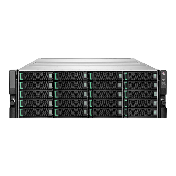
Array Components Each array has the following components: A chassis Two storage controllers Two power supplies for each controller One NIC on each controller Up to 24 2.5-inch NVMe SSDs Two OCP expansion slots Support for dual/quad 1G, 10G BaseT, 10GbE SFP+, 25GbE SFP28, 100GbE QSFP28, 32Gb FC Check HPE InfoSight for the latest updated configurations and specifications for your specific array model. -
Page 48: Shut Down The Array Using The Gui
Documentation Feedback: [email protected] Slot 1 Slot 6 Slot 2 Serial port Slot 3 OCP expansion slot Slot 4 Eth0 ports, onboard 5 Slot 5 Array rear view - HPE Alletra 6010 In this example, quad fc ports are installed in Slot 1 and quad eth ports are installed in Slot 2 and Slot 3. Slot 1 Serial port Slot 2... -
Page 49: Shut Down The Array Using The Cli
Documentation Feedback: [email protected] Shut Down the Array Using the CLI This action shuts down the array and any expansion shelves managed by the array. For most hardware changes you do not need to shut down (power off) the array because the components are redundant and hot swappable. - Page 50 Documentation Feedback: [email protected] Figure 19: Front LEDs Power button Controller health status Power status Controller B ID button Controller A ID button Controller power status The following table describes the front LEDs. Status Power button Solid green indicates that the array is powered on Power status Solid green indicates that power from all installed power supplies is within range...
-
Page 51: Drive Leds
Documentation Feedback: [email protected] Drive LEDs The following shows the drive and LED indicator lights and describes their functions. Drive operation Drive fault Each drive carrier has two LEDs. The following table describes the LEDs. Table 6: Drive LEDs Status Drive fault (bottom left) Amber indicates that the drive has failed or been removed LED off indicates normal drive operation Solid green indicates that the drive is online and ready... -
Page 52: Find The Serial Number Of An Array Using The Gui
Documentation Feedback: [email protected] Array information on the label includes: Serial number Controller A / Controller B location Port mappings The QR code on the label leads to the Welcome Center on HPE InfoSight. Visit the Welcome Center for help setting up your HPE storage array. -
Page 53: Check Array Model, Os Version, And Operating State Using The Gui
Documentation Feedback: [email protected] Active The controller is actively responding to read/write operations from the host or hosts. Standby The controller is powered on, synchronizing mirrored data to the active controller, and available for controller takeover, should it be required. Solo The controller is powered on, responding to reads/writes but there is no standby controller to takeover if a controller takeover is required. - Page 54 Documentation Feedback: [email protected] Example $ array --info $ ctrlr --list Array Components 54...
-
Page 55: Install The Expansion Shelf
Install the Expansion Shelf Use this procedure to install and activate up to two HPE Alletra 2140 expansion shelves, depending on the model of your HPE Storage array. CAUTION: When you activate the expansion shelf, there is a momentary pause in data services from the array. You might need to activate the expansion shelf during a maintenance window. - Page 56 Documentation Feedback: [email protected] OCP cards, if ordered, are shipped separately. Save all original packaging. 2. Install the outer rail assemblies onto the rack. Note: To ensure that the array thumbscrews align correctly, align the rail assembly in exactly 4U of rack space. The bottom stud on the rail assembly inserts into the bottom hole of the bottom unit of the 4U rack space allotted for the array.
- Page 57 Documentation Feedback: [email protected] 4. Secure the chassis to the rack. The chassis has two handles. Each handle has a thumbscrew that holds the chassis to the rails so it does not slide out of the rack. Tighten the thumbscrew in each handle until secure. Install the Expansion Shelf 57...
-
Page 58: Connect Power To The Expansion Shelf
Documentation Feedback: [email protected] Connect Power to the Expansion Shelf Before you begin Before you perform this task, you must have already installed the HPE expansion shelf in a rack. Procedure 1. Plug the power cables into the power supplies on the back of the expansion shelf. 2. -
Page 59: Connect And Activate The Expansion Shelf
Documentation Feedback: [email protected] c) Engage the OCP card latch to secure the card in the slot. Note: LEDs on the OCP card do not light until cables are connected and establish a link. 3. Disconnect both power cables from the power supplies of the standby controller, and then reconnect the power. The controller powers on automatically. - Page 60 Documentation Feedback: [email protected] Array Expansion shelf 1 OCP port 1 DAC port OCP port 2 Expansion shelf 2 3. (Optional) Cable another expansion shelf to the array: For HPE Alletra 6010: You can connect only one expansion shelf. For HPE Alletra 6030, 6050, 6070, 6090: You can connect up to two expansion shelves. a) Connect OCP port P2 of controller A on the array to the DAC port on expander A of the second expansion shelf.
- Page 61 Documentation Feedback: [email protected] Note: Ensure that all drives are detected and all drive LEDs are green before activating the expansion shelf. Activation will fail if any drives are missing or have failed. a) In the array GUI, click Hardware, then select the array that contains the new drives. b) In the array list, click the array that manages the expansion shelf.
-
Page 62: Expansion Shelf Components
The rear of the HPE Alletra 2140 expansion shelf includes the expanders and power supplies. Data and power cabling are done at the rear of the HPE Alletra 2140. The array manages the HPE Alletra 2140 through the expansion cables. There are no network connectors on an AFS4. -
Page 63: Expansion Shelf Leds
Documentation Feedback: [email protected] Slot 1 Expander B 2 Expander A Expansion Shelf LEDs Power LED Expander health status Power status Expander B ID Expander A ID Expander power status The expansion shelf front LEDs are located on the right handle. The power button on the right handle turns the expanders on and off. -
Page 64: Drive Leds
Documentation Feedback: [email protected] Status Expander A ID Blue LED changes state when an ID command is received Off indicates expander power is off Expander health status Solid green indicates the expander is running and system status is healthy Blinking amber indicates a degraded state, such as a fan failure or PSU failure Solid amber indicates the system is over temperature Off indicates power is off... -
Page 65: Maintenance Procedures
Maintenance Procedures The following topics describe maintenance procedures for the HPE storage array. Drive Maintenance The procedures for maintaining drives are the same for the following: Solid State Drives (SSDs) Arrays Expansion Shelves How the Storage Array Handles a Failed Drive The HPE storage array is designed to be highly available, with redundant components. - Page 66 Documentation Feedback: [email protected] Information required: RMA (Return Materials Authorization) work order Case number Array name or serial number The array serial number can be found on the pullout System Info tab. Support contact: See Support. HPE recommends using the Maintenance Window functionality within the HPE InfoSight portal to inform HPE Support of upcoming maintenance windows.
- Page 67 Documentation Feedback: [email protected] 2. Identify the failed drive. A failed drive has an amber drive fault LED. 1 Drive fault 3. Release and remove the drive from the drive carrier. a) To release the handle, press the release tab toward the carrier LEDs. b) Pull the drive carrier handle to remove the drive from the chassis.
-
Page 68: Controller Maintenance
Documentation Feedback: [email protected] Controller Maintenance You can replace the following components on a controller: Network interface card (NIC) Fibre Channel (FC) host bus adapter (HBA) Storage class memory (SCM) card Note: If any non-replaceable component on a controller fails, replace the entire controller. Replace a Controller Use this procedure to replace a controller in your HPE storage array. - Page 69 Documentation Feedback: [email protected] Replacement controllers are shipped with empty PCIe cages and without an OCP card or power supplies installed. Before installing the replacement controller, you must move the PCIe cage, OCP card, and power supplies from the failed controller to the replacement controller. Important: Before you attempt to replace the controller: Do not remove the failed controller until you are ready to install the replacement.
- Page 70 Documentation Feedback: [email protected] Controller release lever (open) Chassis 2 Controller Important: To avoid electrostatic damage, place array components on a grounded anti-static mat. Use an ESD wrist strap during removal and replacement. 3. Remove the empty primary PCIe cage (left) from the new controller. a) Lift the tab of the fastener and turn the fastener one half turn (180°) counter clockwise to release the PCIe cage.
- Page 71 Documentation Feedback: [email protected] Fastener Connector 2 Riser card 4. Move the primary PCIe cage (left) from the failed controller to the new controller. a) Lift the tab of the fastener and turn the fastener one half turn (180°) counter clockwise to release the PCIe cage. b) Grasp the PCIe cage with both hands and lift the cage out of the controller to unseat the underlying riser card from its connector.
- Page 72 Documentation Feedback: [email protected] Guide post Riser card 2 Groove d) With the riser card and connector properly aligned, press down on the top of the PCIe cage to seat the riser card in the connector. e) Press down on the fastener and turn the fastener tab one half turn (180°) clockwise to secure the PCIe cage. 5.
- Page 73 Documentation Feedback: [email protected] Right PCIe cage Riser card Fastener Connector 6. Move the secondary PCIe cage (right), if present, from the failed controller to the new controller. a) Lift the tab of the fastener and turn the fastener one half turn (180°) counter clockwise to release the PCIe cage. b) Grasp both sides of the PCIe cage and lift the cage out of the controller to unseat the underlying riser cards from their connectors.
- Page 74 Documentation Feedback: [email protected] Guide post Riser card Groove Connector d) With the riser cards and connectors properly aligned, press down on the top of the PCIe cage to seat the riser cards in their connectors. e) Press down on the fastener and turn the fastener tab one half turn (180°) clockwise to secure the PCIe cage. 7.
- Page 75 Documentation Feedback: [email protected] OCP card OCP card latch b) Remove the slot cover from the OCP expansion slot on the back of the controller. c) Gently insert the OCP card into the expansion slot of the replacement controller. Be sure the OCP card is properly seated. d) Engage the OCP card latch to secure the card in the slot.
-
Page 76: Replace A Pcie Card
Documentation Feedback: [email protected] Note: If firmware updates are required, the new controller can take longer to appear in the UI. If the controller takes longer than 45 minutes to report an Active/Standby state, contact HPE Support for assistance. 11. Return the failed controller as directed on the RMA work order that came with the replacement kit. Replace a PCIe Card Use this procedure to replace existing network interface cards (NICs), host bus adapters (HBAs), or storage class memory (SCM) on your HPE storage array. - Page 77 Documentation Feedback: [email protected] Important: Controllers may only be serviced in Standby mode. Never remove a controller running in Active mode. You do not have to shut down the array or expansion shelf to replace or add a component. The storage array can function with one active controller while the component is added on the standby controller.
- Page 78 Documentation Feedback: [email protected] Controller release lever (open) Chassis 2 Controller Important: To avoid electrostatic damage, place array components on a grounded anti-static mat. Use an ESD wrist strap during removal and replacement. 3. Remove the PCIe cage from the controller. For the primary cage (left), proceed to Step 4.
- Page 79 Documentation Feedback: [email protected] Fastener Connector 2 Riser card c) Turn the PCIe cage upside down and place it on a flat surface. 5. Remove the secondary PCIe cage (right), if present, from the controller. Note: The HPE Alletra 6010 model does not include a secondary PCIe cage. a) Lift the tab of the fastener and turn the fastener one half turn (180°) counter clockwise to release the PCIe cage.
- Page 80 Documentation Feedback: [email protected] Right PCIe cage Riser card Fastener Connector c) Turn the PCIe cage upside down and place it on a flat surface. 6. Remove the PCIe card. a) Loosen the thumbscrew on the PCIe card holder. Maintenance Procedures 80...
- Page 81 Documentation Feedback: [email protected] Thumbscrew PCIe card PCIe card holder Riser card b) Open the PCIe card holder. PCIe card Rubber tab Connector PCIe cage slot c) Pull the PCIe card straight out of the card slot. 7. Insert the new PCIe card. a) Insert the new PCIe card into the card slot.
- Page 82 Documentation Feedback: [email protected] Guide post Riser card 2 Groove b) With the riser card and connector properly aligned, press down on the top of the PCIe cage to seat the riser card in the connector. c) Press down on the fastener and turn the fastener tab one half turn (180°) clockwise to secure the PCIe cage. 10.
- Page 83 Documentation Feedback: [email protected] Guide post Riser card Groove Connector b) With the riser cards and connectors properly aligned, press down on the top of the PCIe cage to seat the riser cards in their connectors. c) Press down on the fastener and turn the fastener tab one half turn (180°) clockwise to secure the PCIe cage. 11.
-
Page 84: Replace An Sfp Transceiver
Documentation Feedback: [email protected] Replace an SFP Transceiver Use this procedure to replace a failed SFP transceiver on your HPE storage array. Before you begin Time required: 5 minutes Parts required: Replacement SFP transceiver ordered from HPE Tools required: ESD (electrostatic discharge) strap or appropriate grounding device Information required: RMA (Return Materials Authorization) work order Case number... -
Page 85: Replace A Fan
Documentation Feedback: [email protected] 4. Replace the SFP transceiver. a) With the retaining latch closed, gently slide the new SFP transceiver into the port. b) Remove the dust cover from the new SFP transceiver. c) Insert the cable into the new SFP transceiver. 5. - Page 86 Documentation Feedback: [email protected] HPE recommends using the Maintenance Window functionality within the HPE InfoSight portal to inform HPE Support of upcoming maintenance windows. Refer to https://infosight.hpe.com/dashboards/nimble/wellness/maintenance-windows for more information. Important: Controllers may only be serviced in Standby mode. Never remove a controller running in Active mode. You do not have to shut down the array or expansion shelf to replace or add a component.
-
Page 87: Replace The Usb Boot Device
Documentation Feedback: [email protected] Note: The HPE Alletra 6030, 6050, 6070, and 6090 model array have six fans (shown). The HPE Alletra 6010 model array has only four fans. Fans are numbered sequentially, right to left in this illustration. Fan 1 Fan 6 c) Gently push the new fan into the empty slot until you hear the release latch click into place. - Page 88 Documentation Feedback: [email protected] Tools required: ESD strap or appropriate grounding device Information required: RMA (Return Materials Authorization) work order Case number Array name or serial number The array serial number can be found on the pullout System Info tab. Support contact: See Support.
- Page 89 Documentation Feedback: [email protected] d) Pull the controller release levers down until they stop. The controller ejects slightly from the chassis. e) Supporting the weight of the controller, pull the controller release levers to slide the controller out of the chassis. Then place the controller on a flat surface.
-
Page 90: Fail Over A Controller Using The Gui
Documentation Feedback: [email protected] USB ports Left PCIe cage USB boot device Fans 3 Secondary PCIe cage (if present) b) Gently but firmly pull the USB boot device out of its port. c) Insert the new boot device into the same USB port. You should feel it seat into the port. -
Page 91: Fail Over A Controller Using The Cli
Documentation Feedback: [email protected] Procedure 1. In the GUI, choose Hardware. 2. From the list of arrays, click the array you want to fail over. 3. In the Array view, note which controller is Active and which is Standby. 4. Click Make Active on the Standby controller. 5. -
Page 92: Expander Maintenance
Documentation Feedback: [email protected] Expander Maintenance You can replace the fan in an expander. If any non-replaceable component in an expander fails, replace the entire expander. Replace an Expander Use this procedure to replace an expander in your expansion shelf. Before you begin Time required: 15 minutes per expander (Do not exceed 15 minutes to avoid overheating.) Parts required:... -
Page 93: Power Supply Maintenance
Documentation Feedback: [email protected] d) Pull the release levers down until they stop. The expander ejects slightly from the chassis. e) Supporting the weight of the expander, pull the release levers to slide the expander out of the chassis. Then place the expander on a flat surface. - Page 94 Documentation Feedback: [email protected] Information required: RMA (Return Materials Authorization) work order Case number Array name or serial number The array serial number can be found on the pullout System Info tab. Support contact: See Support. HPE recommends using the Maintenance Window functionality within the HPE InfoSight portal to inform HPE Support of upcoming maintenance windows.
-
Page 95: Replace Ac Power Supplies With Dc Power Supplies
Documentation Feedback: [email protected] Power cord Strain relief strap 2 Power supply handle 7. Connect the power cord to the power source. Power is automatically restored to the PSU as soon as the cord is plugged in. Replace AC Power Supplies with DC Power Supplies Use this procedure to replace the AC power supply units (PSUs) on your HPE storage array with DC PSUs. - Page 96 Documentation Feedback: [email protected] Procedure 1. Install the provided ground bracket. a) Fit the ground bracket over the four T-studs on the left side of the array chassis near the rear. Ground bracket Chassis T-studs M4 nut b) Slide the bracket to engage the T-studs, and secure the bracket to the chassis with the provided M4 nut. 2.
-
Page 97: Replace A Dc Power Supply
Documentation Feedback: [email protected] Power supply LED Power supply handle 2 Power supply release lever 5. Insert the new PSU. Push in gently until you hear a click. Do not force the power supply. If it does not slide in properly, remove it and try again. The DC PSU has an internal fuse for overload protection. - Page 98 Documentation Feedback: [email protected] Parts required: Replacement DC power supply ordered from HPE Information required: RMA (Return Material Authorization) work order Case number Array serial number Tools required: ESD (electrostatic discharge) strap or appropriate grounding device Phillips screwdriver Support contact: See Support. HPE recommends using the Maintenance Window functionality within the HPE InfoSight portal to inform HPE Support of upcoming maintenance windows.
- Page 99 Documentation Feedback: [email protected] Power supply release lever Ground screw Connector cover Power supply LED 3 Connector screws b) Remove the connector cover from the PSU. c) Unscrew the two wire connections labeled + (RTN) and - (-48V) from the PSU and pull the wires out. d) Remove the PSU.
-
Page 100: Chassis Maintenance
Documentation Feedback: [email protected] Chassis Maintenance If your existing chassis needs to be replaced, you can move your array components (drives, controllers, and power supplies) with all network cabling to a new chassis ordered from HPE Storage. Replace the Chassis Use this procedure to replace the chassis of your HPE storage array or expansion shelf. Before you begin Time required: 1 hour... - Page 101 Documentation Feedback: [email protected] a) Slide the black release tab toward the carrier LED. The handle springs open. b) Pull the drive carrier handle to remove the drive in slot 1 from the existing array. Use firm, steady pressure. c) Slide the drive into the drive bay of slot 1 on the new chassis. Do not force the drive. If it does not slide in smoothly, remove it and start again.
- Page 102 Documentation Feedback: [email protected] Thumbscrew Controller 2 Controller release lever 8. Move the System Info label from the old chassis to the new chassis. a) With the System Info label partially extended, slide a flat card over the label to depress the left and right corner tray lock tabs on the chassis.
-
Page 103: Upgrade Procedures
Upgrade Procedures Your HPE storage array can be upgraded to add SSDs to increase capacity, as well as by installing new NICs, FC HBAs, or SCM cards and cabling additional expansion shelves. To check supported upgrades for your array, refer to the Array Configuration Matrix available on InfoSight at :https://infosight.hpe.com/InfoSight/media/local/active/89/HPE%20Alletra%206000%20Config%20Matrix.pdf Upgrade SSDs Use this procedure to add SSDs to your HPE storage array or expansion shelves. - Page 104 Documentation Feedback: [email protected] Drive set A Drive set B Procedure 1. Gently pull the front bezel away from the array chassis. Bezel Chassis 2. Release and remove the empty drive carrier from the chassis. a) To release the handle, press the release tab toward the carrier LEDs. b) Pull the handle to remove the empty carrier from the chassis.
- Page 105 Documentation Feedback: [email protected] 3. Slide the new drive into the empty drive bay. Do not force the drive. If it does not slide in smoothly, remove it and try again. 4. Close the drive carrier handle. Push the handle until it fully engages with the release tab. 5.
-
Page 106: Upgrade A Pcie Card
Documentation Feedback: [email protected] Upgrade a PCIe Card Use this procedure to upgrade network interface cards (NICs), host bus adapters (HBAs), or storage class memory (SCM) in your HPE storage array, including upgrading from dual to quad port NICs or HBAs. Each upgrade kit contains two PCIe cards. Before you begin Time required: 15 minutes per controller... - Page 107 Documentation Feedback: [email protected] halt --array array_name --controller {A | B} 2. Remove the controller from the chassis. a) Disconnect the power cords from the two controller power supplies. b) Label all cables to ensure proper recabling later, then remove them from the controller. c) Loosen the left and right thumbscrews to free the controller release levers from the controller.
- Page 108 Documentation Feedback: [email protected] For the primary cage (left), proceed to Step 4. For the secondary cage (right), proceed to Step 5. 4. Remove the primary PCIe cage (left) from the controller. a) Lift the tab of the fastener and turn the fastener one half turn (180°) counter clockwise to release the PCIe cage. b) Grasp the PCIe cage with both hands and lift the cage out of the controller to unseat the underlying riser card from its connector.
- Page 109 Documentation Feedback: [email protected] Right PCIe cage Riser card Fastener Connector c) Turn the PCIe cage upside down and place it on a flat surface. 6. Remove the PCIe card. a) Loosen the thumbscrew on the PCIe card holder. Upgrade Procedures 109...
- Page 110 Documentation Feedback: [email protected] Thumbscrew PCIe card PCIe card holder Riser card b) Open the PCIe card holder. PCIe card Rubber tab Connector PCIe cage slot c) Pull the PCIe card straight out of the card slot. 7. Insert the new PCIe card. a) Insert the PCIe card into the card slot.
- Page 111 Documentation Feedback: [email protected] Guide post Riser card 2 Groove b) With the riser card and connector properly aligned, press down on the top of the PCIe cage to seat the riser card in the connector. c) Press down on the fastener and turn the fastener tab one half turn (180°) clockwise to secure the PCIe cage. 10.
- Page 112 Documentation Feedback: [email protected] Guide post Riser card Groove Connector b) With the riser cards and connectors properly aligned, press down on the top of the PCIe cage to seat the riser cards in their connectors. c) Press down on the fastener and turn the fastener tab one half turn (180°) clockwise to secure the PCIe cage. 11.
-
Page 113: Upgrade The Controllers
Documentation Feedback: [email protected] b) For HBAs: Communicate the new Fibre Channel configuration out to the fabric. fc --update_config Important: Use this command only when upgrading an HBA, not when replacing a failed HBA. Running the command outside of an upgrade causes the WWPNs on the HBA to change, triggering an outage. WWPN values are tied to the physical slot in the system, not the physical HBA. - Page 114 Documentation Feedback: [email protected] Original Model To Model HPE Alletra 6010 HPE Alletra 6030, 6050, 6070, 6090 Upgrade to HPE Alletra 6030, 6050 strongly recommends 1600W PSU for highest redundancy Upgrade to HPE Alletra 6070, 6090 requires 1600W PSU HPE Alletra 6030 HPE Alletra 6050, 6070, 6090 Upgrade to HPE Alletra 6050 strongly recommends 1600W PSU for highest redundancy...
- Page 115 Documentation Feedback: [email protected] ctrlr --list --array array_name c) Halt the standby controller. halt --array array_name --controller {A | B} Example $ halt --array array123 --controller A 2. Remove the existing Standby controller to be upgraded. a) Disconnect the power cords from the two controller power supplies. b) Label all cables to ensure proper recabling later, then remove them from the controller.
- Page 116 Documentation Feedback: [email protected] Important: To avoid electrostatic damage, place array components on a grounded anti-static mat. Use an ESD wrist strap during removal and replacement. 3. Remove the empty left PCIe cage from the upgrade controller. a) Lift the tab of the fastener and turn the fastener one half turn (180°) counter clockwise to release the PCIe cage. b) Grasp the PCIe cage with both hands and lift the cage out of the controller.
- Page 117 Documentation Feedback: [email protected] Guide post Riser card 2 Groove d) With the riser card and connector properly aligned, press down on the top of the PCIe cage to seat the riser card in the connector. e) Press down on the fastener and turn the fastener tab one half turn (180°) clockwise to secure the PCIe cage. 5.
- Page 118 Documentation Feedback: [email protected] Right PCIe cage Riser card Fastener Connector 6. Move the right PCIe cage if present, from the existing controller to the upgrade controller. a) Lift the tab of the fastener and turn the fastener one half turn (180°) counter clockwise to release the PCIe cage. b) Grasp both sides of the PCIe cage and lift the cage out of the controller to unseat the underlying riser cards from their connectors.
- Page 119 Documentation Feedback: [email protected] Guide post Riser card Groove Connector d) With the riser cards and connectors properly aligned, press down on the top of the PCIe cage to seat the riser cards in their connectors. e) Press down on the fastener and turn the fastener tab one half turn (180°) clockwise to secure the PCIe cage. Important: If you are upgrading to an HPE Alletra 6030, 6050, 6070, or 6090 controller and your existing array uses 800W power supplies:...
- Page 120 Documentation Feedback: [email protected] 8. Move the power supplies from the existing controller to the upgrade controller. Skip this step if you upgraded the power supplies. a) Push the power supply release lever to the left, grasp the handle, and pull the power supply out of the bay. Power supply release lever Power supply handle b) Slide the power supply into a bay of the controller until it clicks into place.
-
Page 121: Upgrade To 1600W Power Supplies
Documentation Feedback: [email protected] For HPE Alletra 6010 only: Shortly after both controllers are upgraded, the active controller automatically fails over a second time to upgrade the NVRAM format. 15. Verify that the model number of the array has changed. shelf --array array_name --list Look for Model in the list of information. -
Page 122: Hardware And Model Specifications
Documentation Feedback: [email protected] Hardware and Model Specifications This section describes the environmental, electrical, and physical specifications of HPE storage arrays. Hardware Specifications Generic specifications that apply to all models appear first, followed by model-specific hardware specifications. Table 9: Chassis Dimensions and Weight Component Specification Height... -
Page 123: Model Specifications
Maximum rated input current: 9.4-4.5 A Rated input frequency: 50-60 Hz IEC 60320 C14 connector HPE Alletra 2140 expansion shelf rating, configuration and warning information is based on IEC 62368-1. Power supply connectors 800 W power supply: IEC 60320 C14 connector... -
Page 124: Sfp Specifications
Documentation Feedback: [email protected] SFP Specifications Optical Fiber The following tables list supported SFP+, SFP28, and QSFP28 optical transceivers for HPE storage array 10GbE cards, 25GbE cards, 100GbE cards, and 32Gb Fibre Channel (FC) cards. SFP+ Specifications (10GbE) Table 12: Finisar Item Description Description... - Page 125 Documentation Feedback: [email protected] Table 14: Avago Item Description Manufacturer / Part number Avago AFBR-725SMZ Media type Multimode Data Rate 25Gb/s Wavelength 850nm VCSEL laser Applications Ethernet NIC Cards/Adapters Voltage, per power supply 3.3V Connector type LC Duplex RoHS RoHS-compliant Operating temperature 0°...
- Page 126 Documentation Feedback: [email protected] Item Description Voltage, per power supply 3.3V Connector type LC Duplex RoHS RoHS-compliant Operating temperature 0° to 70°C (32° to 158°F) Maximum link length Up to 70m on OM3 MMF; 100m on OM4 MMF Table 17: Finisar Item Description Manufacturer / Part number...
- Page 127 Documentation Feedback: [email protected] Table 19: HPE Item Description Description Manufacturer / Part number HPE 845966-B21 HPE 845972-B21 AFBR-89BDDZ-HP1 AFBR-89BDDZ-HP1 Media type Multimode Multimode Data Rate 100Gb/s 100Gb/s Wavelength 850nm 855 nm / 908 nm Applications Ethernet NIC Cards/Adapters Ethernet NIC Cards/Adapters Voltage, per power supply 3.3V...
-
Page 128: Statement Of Volatility
Documentation Feedback: [email protected] Note: HPE recommends OM3 or better Fibre Channel (FC) cables. Table 21: Fibre Channel Cabling Cable Grade Speed Maximum Distance by Optical Cable/Media Type OM1 62.5μm OM2 50μm multi OM3 50μm multi OM4 50μm multi multi mode 200 mode 500 MHz M6 mode 2000 MHz mode 4700 MHz... - Page 129 Documentation Feedback: [email protected] Board Purpose Type Size User Data? Procedure to Clear Motherboard iLO SRAM SRAM Remove Power from unit, remove coin cell battery Motherboard iLO DRAM DRAM Remove Power from unit Motherboard NAND Controller Registers Remove Power from unit Motherboard iLO ASIC Unknown...
- Page 130 Documentation Feedback: [email protected] Board Purpose Type Size User Data? Procedure to Clear Motherboard NIC ROM Flash ROM 256b Motherboard UEFI ROM Flash ROM 32Mb Motherboard DIMM Vital product SPD - EEPROM data Hardware and Model Specifications 130...
-
Page 131: Troubleshooting
Troubleshooting This section describes how to check the temperature of your storage array and expansion shelves to prevent overheating, and keep your system operating at safe levels. Check System Temperature Like any electronic device, HPE storage arrays and expansion shelves generate heat. The amount of heat generated, BTU per hour, depends on the model. -
Page 132: Check System Temperature Using The Gui
Documentation Feedback: [email protected] If you believe that the ambient temperature might exceed the specified safe level for the array, consider stopping I/O and then manually shutting down the array and its attached expansion shelves. That action avoids the possibility of a sudden, unplanned array shutdown. -
Page 133: Regulatory And Safety Information
Regulatory and Safety Information For important safety, environmental, and regulatory information, refer to this section and to the Safety and Compliance Information for Server, Storage, Power, Networking, and Rack Products guide available at http://www.hpe.com/support/Safety-Compliance-EnterpriseProducts. Regulatory Warnings This section describes all regulatory warnings that apply to HPE storage arrays. Regulatory Model Numbers: NMBLA-0003-800, NMBLA-0003-800E, NMBLA-0003-1600 European Union (EU) Warning... - Page 134 Documentation Feedback: [email protected] Taiwan This is a Class A product. In a domestic environment this product may cause radio interference in which case the user may be required to take adequate measures. Warning 警告:為避免電磁干擾,本 品不應安裝或使用於住宅環境 Regulatory and Safety Information 134...
-
Page 135: Safety Warnings
Documentation Feedback: [email protected] Warning This equipment has been tested and found to comply with the limits for a Class A digital device, pursuant to part 15 of the FCC Rules. These limits are designed to provide reasonable protection against harmful interference when the equipment is operated in a commercial environment. -
Page 136: System Safety
Documentation Feedback: [email protected] AC Power Electrical Safety CAUTION: The AC input voltage for each 800W AC power supply is 100 to 240 V. The AC input voltage for each 1600W AC power supply is 200-240 V. Start-up current draw may exceed 8 A. Locate the power switch on the array and the emergency power switch of the room so that you can quickly stop power to the system if an electrical issue occurs.