HP EliteDesk 800 G4 SFF Maintenance And Service Manual
Business pc
Hide thumbs
Also See for EliteDesk 800 G4 SFF:
- Disassembly instructions manual (10 pages) ,
- Maintenance and service manual (147 pages)
Table of Contents
Table of Contents

Related Manuals for HP EliteDesk 800 G4 SFF


Summary of Contents for HP EliteDesk 800 G4 SFF
- Page 1 Maintenance and Service Guide HP EliteDesk 800 G4 SFF Business PC...
- Page 2 HP Inc. under license. user guide, go to http://www.hp.com/support, bound by the terms of the HP End User License Intel, Celeron, and Pentium are trademarks of and follow the instructions to find your Agreement (EULA).
- Page 3 Safety warning notice WARNING! To reduce the possibility of heat-related injuries or of overheating the device, do not place the device directly on your lap or obstruct the device air vents. Use the device only on a hard, flat surface. Do not allow another hard surface, such as an adjoining optional printer, or a soft surface, such as pillows or rugs or clothing, to block airflow.
- Page 4 Safety warning notice...
-
Page 5: Table Of Contents
Table of contents 1 Product features ............................1 Standard configuration features ........................... 1 Front panel components ............................2 Rear panel components ............................3 Serial number location ............................3 2 Illustrated parts catalog ..........................4 Computer major components ..........................4 Miscellaneous parts ............................... 7 3 Routine care, SATA drive guidelines, and disassembly preparation .............. - Page 6 4 Removal and replacement procedures ......................17 Preparation for disassembly ..........................17 Access panel ................................. 18 Front bezel ................................19 Slim optical drive bezel blank ..........................20 Front bezel dust filter ............................21 System board connections ..........................22 Memory ................................23 Populating DIMM sockets ........................
- Page 7 Clearing and resetting the BIOS ........................116 9 Using HP PC Hardware Diagnostics ......................117 Using HP PC Hardware Diagnostics Windows ....................117 Downloading HP PC Hardware Diagnostics Windows ..............117 Downloading the latest HP PC Hardware Diagnostics Windows version ..... 118...
- Page 8 Using HP PC Hardware Diagnostics UEFI ......................118 Starting HP PC Hardware Diagnostics UEFI ..................119 Downloading HP PC Hardware Diagnostics UEFI to a USB flash drive ..........119 Downloading the latest HP PC Hardware Diagnostics UEFI version ......119 Downloading HP PC Hardware Diagnostics UEFI by product name or number (select products only) ....................
-
Page 9: Product Features
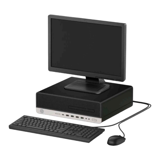
Standard configuration features Features may vary depending on the model. For support assistance and to learn more about the hardware and software installed on your computer model, run the HP Support Assistant utility. NOTE: This computer model can be used in a tower orientation or a desktop orientation. -
Page 10: Front Panel Components
Front panel components Drive configuration may vary by model. Some models have a bezel blank covering the slim optical drive bay. Front panel components Slim optical drive (optional) USB 2.0 port (fast charging port) SD card reader (optional) Audio-out (headphone) jack USB Type-C port (10 Gbit/s data speed) Audio-out (headphone)/Audio-in (microphone) combo jack... -
Page 11: Rear Panel Components
NOTE: Your model may have additional optional ports available from HP. When a graphics card is installed in one of the system board slots, the video connectors on the graphics card and/or the integrated graphics on the system board may be used. The specific graphics card installed and software configuration will determine the behavior. -
Page 12: Illustrated Parts Catalog
Illustrated parts catalog NOTE: HP continually improves and changes product parts. For complete and current information on supported parts for your computer, go to http://partsurfer.hp.com, select your country or region, and then follow the on-screen instructions. Computer major components Item... - Page 13 Item Description USB-C option board HDMI option board DisplayPort option board Thunderbolt 3 option board (uses PCIe slot; not illustrated)) Rear fan (for use only in models with a 95 W processor) WLAN modules Intel 7265 802.11AC 2x2 with Bluetooth M.2 Combo Card (non-vPro) Intel 7265 802.11AC 2x2 with Bluetooth M.2 Combo Card (vPro) Intel Dual Band Wireless-AC 9560 802.11 AC 2x2 WiFi + Bluetooth 5.0 Combo Adapter (vPro) Intel Dual Band Wireless-AC 9560 802.11 AC 2x2 WiFi + Bluetooth 5.0 Combo Adapter (non-vPro)
- Page 14 Item Description Intel Pentium G5500 processor Intel Pentium G5400 processor Intel Celeron G4900 processor (14) RTC battery (15) Bezel blank, slim optical drive (16) Memory module (UDIMM, non-ECC, 1.2v, PC4-2666) 16-GB 8-GB 4-GB (17) Front bezel (18) System board (includes replacement thermal material) (19) Graphics cards (full-height, PCIe x16) AMD Radeon™...
-
Page 15: Miscellaneous Parts
Optical drives, 9.5 mm DVD Blu-ray-writer DVD±RW drive DVD-ROM drive Stand (not illustrated) Miscellaneous parts Description HP USB-Type C to USB Type-A Hub SATA drive power cable DisplayPort cable DVI monitor cable Adapters DisplayPort to VGA DisplayPort to DVI DisplayPort to HDMI 2.0 USB Type-C to USB 3.0... - Page 16 Description Smart card, slim, CCID, USB Conferencing, USB Slim, PS/2 USB, slim Wireless keyboard and mouse Slim, PCR, USB (Brazil and Latin America) Anti-microbial, slim Grey, slim, USB Collaboration, USB Collaboration, wireless Wireless, premium Premium, USB Health care, wired, USB Premium, wireless, keyboard and mouse Mouse PS/2, optical...
-
Page 17: Routine Care, Sata Drive Guidelines, And Disassembly Preparation
Routine care, SATA drive guidelines, and disassembly preparation This chapter provides general service information for the computer. Adherence to the procedures and precautions described in this chapter is essential for proper service. CAUTION: When the computer is plugged into an AC power source, voltage is always applied to the system board. -
Page 18: Preventing Electrostatic Damage To Equipment
Preventing electrostatic damage to equipment Many electronic components are sensitive to ESD. Circuitry design and structure determine the degree of sensitivity. The following packaging and grounding precautions are necessary to prevent damage to electric components and accessories. ● To avoid hand contact, transport products in static-safe containers such as tubes, bags, or boxes. Protect all electrostatic parts and assemblies with conductive or approved containers or packaging. -
Page 19: Recommended Materials And Equipment
Recommended materials and equipment Materials and equipment that are recommended for use in preventing static electricity include: ● Antistatic tape ● Antistatic smocks, aprons, or sleeve protectors ● Conductive bins and other assembly or soldering aids ● Conductive foam ● Conductive tabletop workstations with ground cord of one-megohm +/- 10% resistance ●... -
Page 20: Routine Care
Never cover the ventilation slots on the monitor with any type of material. ● ● Install or enable power management functions of the operating system or other software, including sleep states. Routine care General cleaning safety precautions Never use solvents or flammable solutions to clean the computer. Never immerse any parts in water or cleaning solutions;... -
Page 21: Cleaning The Monitor
The screws used in the computer are not interchangeable. They may have standard or metric threads and may be of different lengths. If an incorrect screw is used during the reassembly process, it can damage the unit. HP Service considerations... -
Page 22: Cables And Connectors
Batteries, battery packs, and accumulators should not be disposed of together with the general household waste. In order to forward them to recycling or proper disposal, please use the public collection system or return them to HP, their authorized partners, or their agents. Chapter 3 Routine care, SATA drive guidelines, and disassembly preparation... -
Page 23: Sata Hard Drives
Data transfer rate 6.0 Gb/s SATA data cable Always use an HP approved SATA 6.0 Gb/s cable as it is fully backwards compatible with the SATA 1.5 Gb/s drives. Current HP desktop products ship with SATA 6.0 Gb/s hard drives. -
Page 24: Cable Management
Cable management Always follow good cable management practices when working inside the computer. ● Keep cables away from major heat sources like the heat sink. ● Do not jam cables on top of expansion cards or memory modules. Printed circuit cards like these are not designed to take excessive pressure on them. -
Page 25: Removal And Replacement Procedures
Removal and replacement procedures Adherence to the procedures and precautions described in this chapter is essential for proper service. After completing all necessary removal and replacement procedures, run the Diagnostics utility to verify that all components operate properly. NOTE: Not all features listed in this guide are available on all computers. Preparation for disassembly Routine care, SATA drive guidelines, and disassembly preparation on page 9 for initial safety procedures. -
Page 26: Access Panel
Access panel Prepare the computer for disassembly (Preparation for disassembly on page 17). Slide the access panel release lever to the left (1) so that it locks into place. Then slide the access panel back (2) and lift it off the computer (3). To install the access panel, reverse the removal procedure. -
Page 27: Front Bezel
Front bezel Prepare the computer for disassembly (Preparation for disassembly on page 17). Remove the access panel (Access panel on page 18). Lift up the three tabs on the top of the bezel (1), and then rotate the bezel off the chassis (2). To install the front bezel, reverse the removal procedure. -
Page 28: Slim Optical Drive Bezel Blank
After removing the slim optical drive bezel blank and installing a slim optical drive, you can install an optional bezel trim piece (available from HP) that surrounds the front of the slim optical drive. Chapter 4 Removal and replacement procedures... -
Page 29: Front Bezel Dust Filter
NOTE: The optional front bezel dust filter is available from HP. To remove, clean, and replace the dust filter: Prepare the computer for disassembly (Preparation for disassembly on page 17). -
Page 30: System Board Connections
System board connections Refer to the following illustration and table to identify the system board connectors for your model. Item System board connector System board label Color Component PCI Express x16 downshifted to X4PCIEXP White Expansion card a x4 PCI Express x1 X1PCIEXP2 Black Expansion card... -
Page 31: Memory
Memory The computer comes with double data rate 4 synchronous dynamic random access memory (DDR4-SDRAM) dual inline memory modules (DIMMs). The memory sockets on the system board are populated with at least one preinstalled memory module. To achieve the maximum memory support, you can populate the system board with up to 64 GB of memory configured in a high-performing dual-channel mode. -
Page 32: Removing And Installing Dimms
DIMM and one 1 GB DIMM, and Channel B should be populated with the other two 1 GB DIMMs. With this configuration, 4 GB will run as dual-channel and 1 GB will run as single-channel. In any mode, the maximum operational speed is determined by the slowest DIMM in the system. ●... - Page 33 Push the module down into the socket, ensuring that the module is fully inserted and properly seated. Make sure the latches are in the closed position (3). Replace the access panel. If the computer was on a stand, replace the stand. Reconnect the power cord and turn on the computer.
-
Page 34: Expansion Card
Expansion card For a list of available expansion cards, see Computer major components on page The computer has two PCI Express x1 expansion sockets, one PCI Express x16 expansion socket, and one PCI Express x16 expansion socket that is downshifted to a x4 socket. NOTE: The PCI Express sockets support only low profile cards. - Page 35 If you are removing a PCI Express x1 card, hold the card at each end and carefully rock it back and forth until the connectors pull free from the socket. Lift the card straight up (1) then away from the inside of the chassis (2) to remove it.
- Page 36 If you are removing a PCI Express x16 card, pull the retention arm on the back of the expansion socket away from the card (1) and carefully rock the card back and forth until the connectors pull free from the socket. Lift the card straight up (2) then away from the inside of the chassis (3) to remove it.
- Page 37 To install a new expansion card, hold the card just above the expansion socket on the system board then move the card toward the rear of the chassis (1) so that the bottom of the bracket on the card slides into the small slot on the chassis.
-
Page 38: Drives
Drives For a list of available drives, see Computer major components on page Drive positions Drive positions 3.5-inch secondary hard drive bay 3.5-inch primary hard drive bay 2.5-inch hard drive bay 9.5 mm slim optical drive bay NOTE: The drive configuration on your computer may be different than the drive configuration shown above. -
Page 39: Removing A 9.5 Mm Slim Optical Drive
IMPORTANT: To prevent loss of work and damage to the computer or drive: If you are inserting or removing a drive, shut down the operating system properly, turn off the computer, and unplug the power cord. Do not remove a drive while the computer is on or in standby mode. Before handling a drive, be sure that you are discharged of static electricity. - Page 40 Push the green release latch on the right rear side of the drive toward the center of the drive (1), and then slide the drive forward and out of the bay (2). Chapter 4 Removal and replacement procedures...
-
Page 41: Installing A 9.5 Mm Slim Optical Drive
Installing a 9.5 mm slim optical drive Prepare the computer for disassembly (Preparation for disassembly on page 17). Remove the access panel (Access panel on page 18). If you are installing a slim optical drive in a bay covered by a bezel blank, remove the front bezel and then remove the bezel blank. -
Page 42: Removing A 3.5-Inch Hard Drive
Connect the power cable and data cable to the rear of the drive. Connect the opposite end of the data cable to one of the light-blue SATA connectors on the system board labeled SATA1 or SATA2. NOTE: Refer to System board connections on page 22 for an illustration of the system board drive connectors. - Page 43 Pull the release lever next to the rear of the hard drive outward (1). While pulling the release lever out, lift the rear of the drive up (2), and then slide the front of the drive back and lift it out of the bay (3). Remove the four mounting screws (two on each side) from the old drive.
-
Page 44: Installing A 3.5-Inch Hard Drive
If replacing a 3.5-inch hard drive, transfer the mounting screws from the old hard drive to the new hard drive. If you are adding a second 3.5-inch hard drive, you can purchase extra mounting screws from HP. Install four silver-and-blue 6-32 mounting screws (two on each side of the drive). - Page 45 – Secure the drive to the bay adapter bracket by installing four black M3 adapter bracket screws through the underside of the bracket and into the drive. Drives...
- Page 46 Install four 6-32 silver-and-blue mounting screws in the adapter bracket (two on each side of – the bracket). Align the mounting screws on the front of the hard drive with the slots on the drive cage and press the front of the drive down and forward into the bay (1). Then press the rear of the drive down into the drive bay (2) to lock it in place.
- Page 47 Connect the power cable (1) and data cable (2) to the rear of the hard drive. NOTE: If the 3.5-inch hard drive is the primary drive, connect the other end of the data cable to the dark-blue SATA connector on the system board labeled SATA0. If it is a secondary hard drive, connect the other end of the data cable to one of the light-blue SATA connectors on the system board.
-
Page 48: Drive Cage
Drive cage Rotate the drive cage to remove and install a 2.5-inch hard drive, and to access components underneath. Prepare the computer for disassembly (Preparation for disassembly on page 17). Remove the access panel (Access panel on page 18). Rotate the drive cage to its upright position. Rotate the drive cage back down to its normal position. -
Page 49: Removing A 2.5-Inch Hard Drive
Removing a 2.5-inch hard drive Prepare the computer for disassembly (Preparation for disassembly on page 17). Remove the access panel (Access panel on page 18). Rotate the drive cage to its upright position (Drive cage on page 40). Disconnect the power cable (1) and data cable (2) from the rear of the hard drive. Pull the release lever at the rear of the drive outward (1). -
Page 50: Installing A 2.5-Inch Hard Drive
Install four black-and-blue M3 mounting screws (two on each side of the drive). NOTE: M3 metric mounting screws can be purchased from HP. When replacing a drive, transfer the four mounting screws from the old drive to the new drive. - Page 51 Align the mounting screws on the drive with the J-slots on the sides of the drive bay. Press the drive into the drive bay, and then slide the drive forward until it locks in place. Connect the power cable (1) and data cable (2) to the rear of the hard drive. NOTE: If the 2.5-inch hard drive is the primary drive, connect the other end of the data cable to the dark-blue SATA connector on the system board labeled SATA0.
-
Page 52: Removing And Installing An M.2 Ssd Storage Card
Removing and installing an M.2 SSD storage card NOTE: The computer supports 2230 and 2280 M.2 SSD cards. Prepare the computer for disassembly (Preparation for disassembly on page 17). Remove the access panel (Access panel on page 18). Remove the front bezel (Front bezel on page 19). - Page 53 To install an M.2 SSD card, slide the pins on the card into the system board connector while holding the card at approximately a 30° angle (1). Press the other end of the card down (2), and then secure the card with the screw (3).
-
Page 54: Wlan Module
WLAN module The WLAN module installs into a connector on the system board. For a list of available WLAN modules, see Computer major components on page To remove the WLAN module: Prepare the computer for disassembly (Preparation for disassembly on page 17). -
Page 55: Hood Lock
Hood lock The hood lock is secured to the back of the computer. Prepare the computer for disassembly (Preparation for disassembly on page 17). Remove the access panel (Access panel on page 18). Disconnect the cable from the system board connector labeled HLCK (1), and then remove the cable from the clip on the fan duct (2). -
Page 56: Card Reader
Card reader The card reader is secured to the front of the computer behind the bezel. Prepare the computer for disassembly (Preparation for disassembly on page 17). Remove the access panel (Access panel on page 18). Remove the front bezel (Front bezel on page 19). -
Page 57: Antennas
Antennas The wireless antennas are secured to both the front and back of the computer behind. Prepare the computer for disassembly (Preparation for disassembly on page 17). Remove the access panel (Access panel on page 18). Remove the front bezel (Front bezel on page 19). - Page 58 Remove the Torx T15 screw (2) that secures the antenna to the front of the chassis (2), and then pull the antenna off the chassis and the cable out of the chassis (3). To install the antennas, reverse the removal procedure. Chapter 4 Removal and replacement procedures...
-
Page 59: Air Duct
Air duct The air duct sits over the fan sink. Air ducts are available for models that use up to a 65 W processor and models that use a 95 W processor. Prepare the computer for disassembly (Preparation for disassembly on page 17). -
Page 60: Option Board
Option board An option board can be installed near the back of the system board that provides an additional connector on the rear I/O panel. Prepare the computer for disassembly (Preparation for disassembly on page 17). Remove the access panel (Access panel on page 18). -
Page 61: Optional Rear Port
Optional rear port The optional rear port is attached to the rear of the chassis with two screws. To remove the optional rear port: Prepare the computer for disassembly (Preparation for disassembly on page 17). Remove the access panel (Access panel on page 18). -
Page 62: Fan Sink
Fan sink CAUTION: The bond between the fan sink and the processor may be very tight. If the computer will power on, before removing the fan sink, turn on the computer until it warms the fan sink. Warming the heat sink lessens the bond between the fan sink and the processor, thereby making separating them easier. - Page 63 Lift the fan sink from atop the processor (3) and set it on its side to keep from contaminating the work area with thermal grease. Up to 65 W processor models 95 W processor models Fan sink...
- Page 64 Each time the heat sink is removed, apply fresh thermal grease to the top of the processor (1) and thoroughly clean the thermal grease from the bottom of the heat sink (2). Replacement thermal material is included with the fan sink and system board spare part kits. When reinstalling the fan sink, make sure that its bottom has been cleaned with an alcohol wipe and fresh thermal grease has been applied to the top of the processor.
-
Page 65: Fan
The fan is secured to the back of the computer. IMPORTANT: The rear fan is used only in models with a 95 W processor. Prepare the computer for disassembly (Preparation for disassembly on page 17). Remove the access panel (Access panel on page 18). -
Page 66: Processor
After installing a new processor onto the system board, always update the system ROM to ensure that the latest version of the BIOS is being used on the computer. The latest system BIOS can be found on the Web at: http://www.hp.com/support. Chapter 4 Removal and replacement procedures... -
Page 67: Power Supply
Computer major components on page WARNING! To reduce potential safety issues, only the power supply provided with the computer, a replacement power supply provided by HP, or a power supply purchased as an accessory from HP should be used with the computer. WARNING! Voltage is always present on the system board when the computer is plugged into an active AC outlet. -
Page 68: Speaker
Speaker The speaker is attached to the front of the rotating drive cage. Prepare the computer for disassembly (Preparation for disassembly on page 17). Remove the access panel (Access panel on page 18). Remove the front bezel (Front bezel on page 19). -
Page 69: System Board
System board NOTE: All system board spare part kits include replacement thermal material. NOTE: System board appearance may vary. Prepare the computer for disassembly (Preparation for disassembly on page 17). Remove the access panel (Access panel on page 18). Remove the air duct (Air duct on page 51). - Page 70 Disconnect the following cables from the system board: IMPORTANT: Connected cables may vary depending on system configuration. (1) Black drive power connector (SATAPWR0) (2) Hard drive connector (SATA0) (3) Optical drive connector (SATA1) (4) Speaker connector (SPKR) (5) White power supply connector (PWR) (6) White power supply connector (PWRCMD) Remove the eight Torx T15 screws that secure the system board to the chassis.
- Page 71 Slide the system board toward the front of the computer to disengage the I/O panel (1), then lift the rear of the system board upward (2), and then pull it out of the computer (3). When reinstalling the system board, first insert the I/O panel back into the slots in the rear of the chassis, and then align the board with the chassis screw holes.
-
Page 72: System Board Callouts
System board callouts Sys Bd Label Color Component Sys Bd Label Color Component PWRCPU White 4-pin processor power SPKR White Speaker Silver Processor SSD2 Black M.2 solid-state drive CPUFAN White Processor fan SSD1 Black M.2 solid-state drive DIMM4 White Memory module White 6-pin main power DIMM3... -
Page 73: Changing From Desktop To Tower Orientation
The Small Form Factor computer can be used in a tower orientation with an optional tower stand that can be purchased from HP. NOTE: To stabilize the computer in a tower orientation, HP recommends the use of the optional tower stand. Prepare the computer for disassembly (Preparation for disassembly on page 17). -
Page 74: Computer Setup (F10) Utility
Computer Setup (F10) Utility Computer Setup (F10) Utilities Use Computer Setup (F10) Utility to do the following: ● Change settings from the defaults or restore the settings to default values. View the system configuration, including settings for processor, graphics, memory, audio, storage, ●... - Page 75 Use the arrow (left and right) keys to select the appropriate heading. Use the arrow (up and down) keys to select the option you want, then press Enter. To return to the Computer Setup Utilities menu, press Esc. To apply and save changes, select Main > Save Changes and Exit. If you have made changes that you do not want applied, select Ignore Changes and Exit.
-
Page 76: Computer Setup-Main
Integrated MAC Address System Diagnostics If the hard drive has the HP Advanced Diagnostics installed, the application will launch. If HP Advanced Diagnostics is not installed, then a basic version built into the BIOS will provide the capability to perform the following functions: ●... - Page 77 Show test logs ● Language selection Update System BIOS Lets you update the system BIOS from www.hp.com or another network server, from a removable USB drive, or from a file located on the hard drive. Displays current BIOS version information. ●...
-
Page 78: Computer Setup-Security
Table 5-1 Computer Setup—Main (continued) Option Description Apply Factory Defaults Restores the factory system configuration settings to the computer after rebooting. Does not apply to and Exit options in the Security menu. Ignore Changes and Exit Exits Computer Setup without applying or saving any changes. Save Changes and Exit Saves changes to current system configuration, exits Computer Setup, and reboots. - Page 79 Only select Manual in situations in which forensic analysis is to be performed before HP Sure Start Recovery. When this policy is set to manual, HP Sure Start will not correct any issues that are found until the manual recovery key sequence is entered by the local user. This can result in a system that is unable to boot after inputting the manual recovery key sequence.
- Page 80 Table 5-2 Computer Setup—Security (continued) Option Description NOTE: Notify user alerts the user with a POST error on the first boot after the sensor detects removal of the cover. If the password is set, Administrator Password requires that the password be entered to boot the computer if the sensor detects that the cover has been removed.
-
Page 81: Computer Setup-Advanced
Table 5-2 Computer Setup—Security (continued) Option Description Set DriveLock Master Password. Sets the drive’s master password but does not enable DriveLock. Enable DriveLock. Sets the drive’s user password and enables DriveLock. ● Secure Erase Lets you select a hard drive to completely erase. Once a hard drive has been erased with a program that utilizes Secure Erase firmware commands, no file recovery program, partition recovery program, or other data recovery method will be able to extract data from the drive. - Page 82 Table 5-3 Computer Setup—Advanced (for advanced users) (continued) Option Heading ● UEFI Boot Order. Default is enabled. Specify the order in which UEFI boot sources (such as a internal hard drive, USB hard drive, USB optical drive, or internal optical drive) are checked for a bootable operating system image.
- Page 83 Table 5-3 Computer Setup—Advanced (for advanced users) (continued) Option Heading Controls virtualization DMA remapping features of the chipset. Changing this setting requires turning the computer off and then back on. Default is disabled. PCI Express Slot x (enable/disable) Lets you disable individual expansion slots. Default is enabled. M.2 WLAN/BT Lets you disable the wireless module slot.
- Page 84 Table 5-3 Computer Setup—Advanced (for advanced users) (continued) Option Heading NOTE: Serial Port A and/or Serial Port B settings are available depending on installed hardware. I/O Address A/B Lets you specify the address. Default is enabled. Interrupt A/B Lets you specify the address. Default is enabled. Lets you disable the following ports (default is enabled): ●...
- Page 85 Table 5-3 Computer Setup—Advanced (for advanced users) (continued) Option Heading Enables or disables SATA bus and/or device power management. Default is enabled. PCI Express Power Management (enable/disable) Enabling this option permits the PCI Express links to use Active Power State Management (ASPM) to enter lower power states while not in use.
-
Page 86: Computer Setup-Uefi Drivers
Table 5-3 Computer Setup—Advanced (for advanced users) (continued) Option Heading CIRA is Customer Initiated Remote Assistance, an Intel service to help users employing Active Management Technology (AMT). Computer Setup—UEFI Drivers Lets you restart the computer into the 3rd Party Option ROM Management application. You can start this application directly by pressing during startup. -
Page 87: Troubleshooting Without Diagnostics
To assist you in resolving problems online, HP Instant Support Professional Edition provides you with self- solve diagnostics. If you need to contact HP support, use HP Instant Support Professional Edition's online chat feature. Access HP Instant Support Professional Edition at: http://www.hp.com/go/ispe. -
Page 88: Helpful Hints
If it becomes necessary to call for technical assistance, be prepared to do the following to ensure that your service call is handled properly: Be in front of your computer when you call. ● ● Write down the computer serial number, product ID number, and monitor serial number before calling. ●... -
Page 89: Solving General Problems
● If you have installed an operating system other than the factory-installed operating system, check to be sure that it is supported on the system. ● If the system has multiple video sources (embedded, PCI, or PCI-Express adapters) installed (embedded video on some models only) and a single monitor, the monitor must be plugged into the monitor connector on the source selected as the primary VGA adapter. - Page 90 In case of forgotten password, power loss, or computer malfunction, you must manually disable the Smart Cover lock . A key to unlock the Smart Cover Lock is not available from HP. Keys are typically available from a hardware store.
- Page 91 Poor performance. Cause Solution Hard drive fragmented. Defragment hard drive. Program previously accessed did not release reserved memory Restart the computer. back to the system. Virus resident on the hard drive. Run virus protection program. Too many applications running. Close unnecessary applications to free up memory. Add more memory.
- Page 92 System does not power on and the LEDs on the front of the computer are not flashing. Cause Solution If equipped with a voltage selector, check that the voltage selector (located on the rear of the power supply) is set to the appropriate voltage.
-
Page 93: Solving Power Problems
Solving power problems Common causes and solutions for power problems are listed in the following table. Power supply shuts down intermittently. Cause Solution If equipped with a voltage selector, voltage selector switch on Select the proper AC voltage using the selector switch. rear of computer chassis (some models) not switched to correct line voltage (115V or 230V). -
Page 94: Solving Hard Drive Problems
Solving hard drive problems Hard drive error occurs. Cause Solution Hard disk has bad sectors or has failed. In Windows 10, type file in the taskbar search box, and then select File Explorer from the list of applications. In the left column, expand This PC, right-click on a drive, select Properties, and then select the Tools tab. - Page 95 Nonsystem disk/NTLDR missing message. Cause Solution the File Backup Program option, and then restore the system. Install system files for the appropriate operating system. Hard drive boot has been disabled in Computer Setup. Run the Computer Setup utility and enable the hard drive entry in the Advanced >...
-
Page 96: Solving Media Card Reader Problems
Solving media card reader problems Media card will not work in a digital camera after formatting it in Windows. Cause Solution By default, Windows will format any media card with a capacity Either format the media card in the digital camera or select FAT greater than 32MB with the FAT32 format. -
Page 97: Solving Display Problems
After installing the media card reader and booting to Windows, the reader and the inserted cards are not recognized by the computer. Cause Solution The operating system needs time to recognize the device if the Wait a few seconds so that the operating system can recognize reader was just installed into the computer and you are turning the reader and the available ports, and then recognize the media the PC on for the first time. - Page 98 Reseat DIMMs. Power on the system. Replace DIMMs one at a time to isolate the faulty module. Replace third-party memory with HP memory. Replace the system board. Blank screen and the power LED flashes Red six times, once every second, followed by a two second pause, and the computer beeps six times.
- Page 99 Dim characters. Cause Solution The brightness and contrast controls are not set properly. Adjust the monitor brightness and contrast controls. Cables are not properly connected. Check that the graphics cable is securely connected to the graphics card (if applicable) or video connector and the monitor. Blurry video or requested resolution cannot be set.
- Page 100 To download a SoftPaq that will assist you with the synchronization, go to the following Web site, select the appropriate monitor, and download either SP32347 or SP32202: http://www.hp.com/support Graphics card is not seated properly or is bad (some models). Reseat the graphics card. Replace the graphics card.
-
Page 101: Solving Audio Problems
Solving audio problems If the computer has audio features and you encounter audio problems, see the common causes and solutions listed in the following table. Headset microphone connected to the front is not working or is very quiet. Cause Solution The front Headset connector supports CTIA (Cellular Telephone Make sure that a CTIA style headset is being used or use an OMTP Industries Association) style headsets and not OMTP (Open Mobile... - Page 102 Sound does not come out of the speaker or headphones. Cause Solution Some applications can select which audio output device is used. Make sure the application has selected the correct audio device. The operating system controls may be set to use a different audio Set the operating system to use the correct audio device.
-
Page 103: Solving Printer Problems
Solving printer problems If you encounter printer problems, see the documentation that came with the printer and to the common causes and solutions listed in the following table. Printer will not print. Cause Solution Printer is not turned on and online. Turn the printer on and make sure it is online. -
Page 104: Solving Keyboard And Mouse Problems
Solving keyboard and mouse problems If you encounter keyboard or mouse problems, see the documentation that came with the equipment and to the common causes and solutions listed in the following table. A wireless keyboard/mouse is not working correctly. Symptoms include lagging mouse movement, jumpy mouse/keyboard, or no function of mouse/keyboard and external drive. -
Page 105: Solving Hardware Installation Problems
Mouse does not respond to movement or is too slow. Cause Solution Mouse may need repair. See the Worldwide Limited Warranty for terms and conditions. Computer is in Sleep state. Press the power button to resume from Sleep state. CAUTION: When attempting to resume from Sleep state, do not hold down the power button for more than four seconds. -
Page 106: Solving Network Problems
DIMM1 or XMM1 must always be installed. DIMM1 must be installed before DIMM2, and DIMM3 must be installed before DIMM4 Replace third-party memory with HP memory. Replace the system board. Solving network problems Some common causes and solutions for network problems are listed in the following table. These guidelines do not discuss the process of debugging the network cabling. - Page 107 Network driver does not detect network controller. Cause Solution Network controller is disabled. Run Computer Setup and enable network controller. Enable the network controller in the operating system using Device Manager. To access Device Manager in Windows 10, type device manager in the taskbar search box, and then select Device Manager from the list of applications.
- Page 108 Diagnostics passes, but the computer does not communicate with the network. Cause Solution Network drivers are not loaded, or driver parameters do not Make sure the network drivers are loaded and that the driver match current configuration. parameters match the configuration of the network controller. Make sure the correct network client and protocol is installed.
-
Page 109: Solving Memory Problems
Management Engine (ME) settings). To avoid damage to the DIMMs or the system board, you must unplug the computer power cord before attempting to reseat, install, or remove a memory module. For those systems that support ECC memory, HP does not support mixing ECC and non-ECC memory. Otherwise, the computer will not boot the operating system. -
Page 110: Solving Cd-Rom And Dvd Problems
Memory is installed incorrectly or is bad. Reseat DIMMs. Power on the system. Replace DIMMs one at a time to isolate the faulty module. Replace third-party memory with HP memory. Replace the system board. Solving CD-ROM and DVD problems If you encounter CD-ROM or DVD problems, see the common causes and solutions listed in the following table or to the documentation that came with the optional device. - Page 111 CD-ROM or DVD devices are not detected or driver is not loaded. Cause Solution Drive is not connected properly or not properly configured. See the documentation that came with the optional device. Movie will not play in the DVD drive. Cause Solution Movie may be regionalized for a different country.
-
Page 112: Solving Usb Flash Drive Problems
Recording or copying CDs is difficult or impossible. Cause Solution Wrong or poor quality media type. Try using a slower speed when recording. Verify that you are using the correct media for the drive. Try a different brand of media. Quality varies widely between manufacturers. -
Page 113: Solving Front Panel Component Problems
Solving front panel component problems If you encounter problems with devices connected to the front panel, refer to the common causes and solutions listed in the following table. A USB device, headphone, or microphone is not recognized by the computer. Cause Solution Device is not properly connected. -
Page 114: Solving Software Problems
● sure it is supported on the system. If you encounter software problems, see the applicable solutions listed in the following table. Computer will not continue and the HP logo does not display. Cause Solution ROM issue - POST error has occurred. -
Page 115: Post Error Messages And Diagnostic Front Panel Leds And Audible Codes
POST error messages and diagnostic front panel LEDs and audible codes This appendix lists the error codes, error messages, and the various indicator light and audible sequences that you may encounter during Power-On Self-Test (POST) or computer restart, the probable source of the problem, and steps you can take to resolve the error condition. - Page 116 Control panel message Description Recommended action RTC (real-time clock) battery may need to problem persists, replace the RTC battery. See be replaced. the Removal and Replacement section for instructions on installing a new battery. 008–Microcode Patch Error Processor is not supported by the BIOS. Upgrade BIOS to proper version.
- Page 117 Run the Drive Protection erroneous error message.) System test under using F2 Diagnostics when booting the computer. Apply hard drive firmware patch if applicable. (Available at http://www.hp.com/support.) POST numeric codes and text messages 109...
- Page 118 System test under using F2 Diagnostics when booting the computer. Apply hard drive firmware patch if applicable. (Available at http://www.hp.com/support.) Back up contents and replace hard drive. 309 – 30C: Hard Disk 3–6: SMART Hard Drive Hard drive is about to fail. (Some hard drives...
- Page 119 Control panel message Description Recommended action Reconfigure card resources and/or run Computer Setup or Windows utilities. 419-Out of Memory Space for Option ROMs Recently added PCI expansion card contains an If a PCI expansion card was recently ▲ option ROM too large to download during POST. added, remove it to see if the problem remains.
-
Page 120: Interpreting System Validation Diagnostic Front Panel Leds And Audible Codes
Control panel message Description Recommended action 90B-Fan Failure The system has detected that a cooling fan is Reseat fan. not operating correctly. Reseat fan cable. Replace fan. 90D-System Temperature Thermal shutdown occurred. The system BIOS Make sure system has proper airflow. has detected your machine was previously shut down to avoid overheating. - Page 121 Thermal System board Patterns of blink/beep codes are determined by using the following parameters: ● 1 second pause occurs after the last major blink. ● 2 second pause occurs after the last minor blink. ● Beep error code sequences occur for the first 5 iterations of the pattern and then stop. ●...
-
Page 122: Password Security And Resetting Cmos
If you lose or forget the password when in stringent security mode, the system can only be reset by System Management Command. This is a way for HP Service and Support to provide a secure method to access the BIOS and command a password reset for a specifically identified unit under the direction of the owner. This scenario may not be covered under warranty. - Page 123 Shut down the operating system properly, then turn off the computer and any external devices, and disconnect the power cord from the power outlet. With the power cord disconnected, press the power button again to drain the system of any residual power.
-
Page 124: Clearing And Resetting The Bios
Clearing and resetting the BIOS The CMOS button resets BIOS settings to default, but does not clear the passwords or affect any of the other Security settings. On Intel systems with advanced manageability features, the CMOS button will also partially unprovision AMT. -
Page 125: Using Hp Pc Hardware Diagnostics
The tool runs within the Windows operating system in order to diagnose hardware failures. If HP PC Hardware Diagnostics Windows is not installed on your computer, first you must download and install it. To download HP PC Hardware Diagnostics Windows, see... -
Page 126: Downloading The Latest Hp Pc Hardware Diagnostics Windows Version
If your PC will not boot into Windows, you can use HP PC Hardware Diagnostics UEFI to diagnose hardware issues. -
Page 127: Starting Hp Pc Hardware Diagnostics Uefi
Downloading HP PC Hardware Diagnostics UEFI to a USB flash drive Downloading HP PC Hardware Diagnostics UEFI to a USB flash drive can be useful in the following situations: HP PC Hardware Diagnostics UEFI is not included in the preinstall image. -
Page 128: Using Remote Hp Pc Hardware Diagnostics Uefi Settings (Select Products Only)
Find out more. Downloading Remote HP PC Hardware Diagnostics UEFI NOTE: HP Remote PC Hardware Diagnostics UEFI is also available as a Softpaq that can be downloaded to a server. Downloading the latest Remote HP PC Hardware Diagnostics UEFI version To download the latest Remote HP PC Hardware Diagnostics UEFI version, follow these steps: Go to http://www.hp.com/go/techcenter/pcdiags. - Page 129 Make your customization selections. Select Main, and then Save Changes and Exit to save your settings. Your changes take effect when the computer restarts. Using Remote HP PC Hardware Diagnostics UEFI settings (select products only) 121...
-
Page 130: Appendix A Battery Replacement
The lithium battery is only used when the computer is NOT connected to AC power. HP encourages customers to recycle used electronic hardware, HP original print cartridges, and rechargeable batteries. For more information about recycling programs, go to http://www.hp.com/recycle. - Page 131 Slide the replacement battery into position, positive side up. The battery holder automatically secures the battery in the proper position. Type 2 To release the battery from its holder, squeeze the metal clamp that extends above one edge of the battery. When the battery pops up, lift it out (1). To insert the new battery, slide one edge of the replacement battery under the lip of the holder with the positive side up.
- Page 132 Insert the new battery and position the clip back into place. NOTE: After the battery has been replaced, use the following steps to complete this procedure. Replace the computer access panel. Plug in the computer and turn on power to the computer. Reset the date and time, your passwords, and any special system setups using Computer Setup.
-
Page 133: Appendix B Power Cord Set Requirements
Power cord set requirements The power supplies on some computers have external power switches. The voltage select switch feature on the computer permits it to operate from any line voltage between 100-120 or 220-240 volts AC. Power supplies on those computers that do not have external power switches are equipped with internal switches that sense the incoming voltage and automatically switch to the proper voltage. -
Page 134: Country-Specific Requirements
Country-Specific Requirements Additional requirements specific to a country are shown in parentheses and explained below. Country Accrediting Agency Country Accrediting Agency Australia (1) EANSW Italy (1) Austria (1) Japan (3) METI Belgium (1) CEBC Norway (1) NEMKO Canada (2) Sweden (1) SEMKO Denmark (1) DEMKO... -
Page 135: Appendix C Statement Of Memory Volatility
Intel-based and AMD-based system boards contain nonvolatile memory subcomponents as originally shipped from HP, assuming that no subsequent modifications have been made to the system and assuming that no applications, features, or functionality have been added to or installed on the system. - Page 136 If a DriveLock password is set, select the Security menu, and scroll down to Hard Drive Utilities under the Utilities menu. Select Hard Drive Utilities, select DriveLock, then uncheck the checkbox for DriveLock password on restart. Select OK to proceed. Select the Main menu, and then select Reset BIOS Security to factory default.
-
Page 137: Nonvolatile Memory Usage
HP Sure Start only) backup of The content is managed Embedded Controller. critical System solely by the HP Sure Start BIOS code, EC Embedded Controller. firmware, and critical computer configuration data for select... - Page 138 Stores Fingerprint reader memory is Only a digitally signed (select products fingerprint programmed by user application can make the only) templates. enrollment in HP call to write to the flash. ProtectTools Security Manager. 130 Appendix C Statement of memory volatility...
-
Page 139: Questions And Answers
HP has provided options in Computer Setup (BIOS) to allow you to run in legacy BIOS, if required by the operating system. Examples of this requirement would be if you upgrade or downgrade the OS. -
Page 140: Using Hp Sure Start (Select Models Only)
BIOS to its previously safe state, without user intervention. Those select computer models ship with HP Sure Start configured and enabled. HP Sure Start is configured and already enabled so that most users can use the HP Sure Start default configuration. The default configuration can be customized by advanced users. -
Page 141: Appendix D Specifications
Specifications Item Metric U.S. Dimensions Width 3.94 in 100 mm Depth 13.3 in 338 mm Height 12.13 in 308 mm Weight 19.82 lb 9.00 kg Max supported weight (desktop orientation) 77 lb 35 kg Temperature range Operating 41° to 113°F 5°... -
Page 142: Index
Full Boot 107 removal and replacement 47 installation 26 Quick Boot 107 HP PC Hardware Diagnostics UEFI removal 26 downloading 119 starting 119 cable management 16 using 118 F10 Setup cable pinouts, SATA data 15... - Page 143 33 software options 7 problems 106 problems 102 rear panel components 3 servicing computer 13 removal 31 Remote HP PC Hardware Diagnostics solid-state drives option board UEFI settings sizes 5, 7 removal and replacement 52 customizing 120 speaker optional rear port...
- Page 144 temperature control 11 tools, servicing 13 Torx T15 screwdriver 13 tower orientation 65 ventilation, proper 11 wireless antennas disconnecting 46 WLAN module removal 46 spare part number 46 136 Index...