Fujitsu AIRSTAGE AUXB09GALH Installation Manual
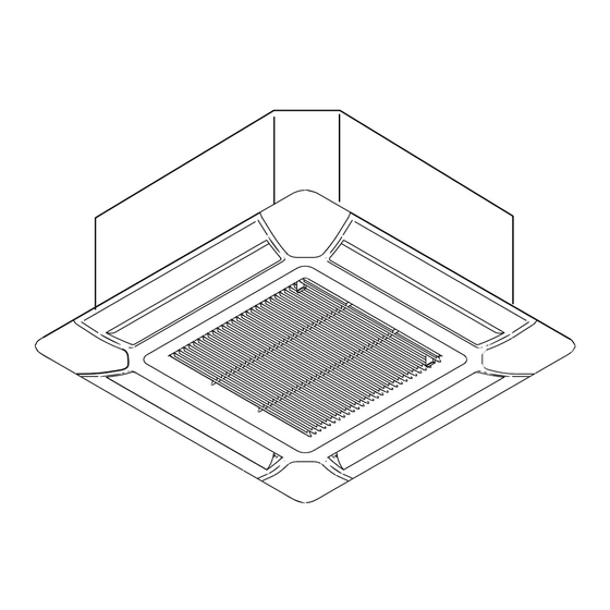
Indoor unit (cassette type)
Hide thumbs
Also See for AIRSTAGE AUXB09GALH:
- Service manual (255 pages) ,
- Installation manual (144 pages) ,
- Operating manual (6 pages)
Table of Contents
Quick Links
AUXB04GBLH
AUXB07GALH
AUXB09GALH
AUXB12GALH
AUXB14GALH
AUXB18GALH
AUXB24GALH
Refer to the rating label for the serial number,
manufactured year and month.
TM
INSTALLATION MANUAL
INSTALLATIONSANLEITUNG
MANUEL D'INSTALLATION
MANUAL DE INSTALACIÓN
Únicamente para personal de servicio autorizado.
MANUALE DI INSTALLAZIONE
A uso esclusivo del personale tecnico autorizzato.
ΕΓΧΕΙΡΙΔΙΟ ΕΓΚΑΤΑΣΤΑΣΗΣ
ΕΣΩΤΕΡΙΚΗ ΜΟΝΑΔΑ (Τύπος Κασέτας)
Μόνο για εξουσιοδοτημένο τεχνικό προσωπικό.
MANUAL DE INSTALAÇÃO
РУКОВОДСТВО ПО УСТАНОВКЕ
ВНУТРЕННИЙ МОДУЛЬ (кассетного типа)
Только для авторизованного обслуживающего персонала.
INDOOR UNIT (Cassette Type)
For authorized service personnel only.
INNENGERÄT (Kassettentyp)
Nur für autorisiertes Fachpersonal.
UNITÉ INTÉRIEURE (type cassette)
Pour le personnel agréé uniquement.
UNIDAD INTERIOR (Tipo casete)
UNITÀ INTERNA (tipo a cassetta)
UNIDADE INTERIOR (Tipo Cassete)
Apenas para técnicos autorizados.
MONTAJ KILAVUZU
İÇ ÜNİTE (Kaset Tipi)
Yalnızca yetkili servis personeli için.
[Original instructions]
PART No. 9371022611
MADE IN P.R.C.
Table of Contents

Related Manuals for Fujitsu AIRSTAGE AUXB09GALH


Summary of Contents for Fujitsu AIRSTAGE AUXB09GALH
- Page 1 INSTALLATION MANUAL INDOOR UNIT (Cassette Type) For authorized service personnel only. INSTALLATIONSANLEITUNG INNENGERÄT (Kassettentyp) Nur für autorisiertes Fachpersonal. MANUEL D’INSTALLATION UNITÉ INTÉRIEURE (type cassette) AUXB04GBLH Pour le personnel agréé uniquement. AUXB07GALH MANUAL DE INSTALACIÓN AUXB09GALH AUXB12GALH UNIDAD INTERIOR (Tipo casete) Únicamente para personal de servicio autorizado.
-
Page 2: Table Of Contents
INSTALLATION MANUAL This mark indicates procedures which, if improperly performed, CAUTION might possibly result in personal harm to the user, or damage PART NO. 9371022611 to property. VRF system indoor unit (Cassette type) Read carefully all security information before use or install the air conditioner. Contents Do not attempt to install the air conditioner or a part of the air conditioner by yourself. -
Page 3: Optional Parts
Do not discard any accessories needed for installation until the installation work has been 3. INSTALLATION WORK completed. Correct initial installation location is important because it is difficult to move unit after it is Name and Shape Q’ty Application installed. Operating manual 3.1. -
Page 4: Discharge Direction Setting
H: Maximum height from floor to ceiling Fig. D Drain pipe (O.D. ø25.4) Unit: mm H (mm) Model name AUXB04 AUXB07 AUXB09 AUXB12 AUXB14 AUXB18 AUXB24 Standard mode 2,700 2,700 2,700 2,700 2,700 2,700 2,700 High Ceiling 3,000 3,000 3,000 3,000 mode * Be sure to make the function settings with the remote controller according to the... -
Page 5: Pipe Requirement
4.3.3. Pipe connection 4.2. Pipe requirement When the flare nut is tightened properly by Tighten with 2 your hand, hold the body side coupling with wrenches. CAUTION a separate spanner, then tighten with a Holding torque wrench. (See the table below for the Refer to the installation manual for the outdoor unit for description of allowable pipe wrench flare nut tightening torques.) -
Page 6: Electrical Wiring
NOTE: When lifting up drain: Check for drainage Drain pipe • Height of inclined pipe should be less than 700 mm from the ceiling. A rise dimension Pour about 1 liter of water over this range will cause leakage. from the position shown in the •... -
Page 7: Wiring Method
Breaker should be installed at every refrigerant system. Do not use a breaker in a different 6.3. Unit wiring refrigerant system. Refer to the table for the breaker specifications of each installation condition. Perform Before attaching the cable to terminal block. the power crossover wiring within the range of the same refrigerant system. -
Page 8: Connection Of Wiring
6.3.2. Transmission and Remote controller cable 3WIRE Transmission cable DIP switch (SW1) 30 mm 2WIRE Y1,Y2,Y3: Remote controller cable Shielded cable (no fi lm) 40 mm Cable tie (Medium) (Accessories) Remote controller cable For 3-wire type For 2-wire type X1, X2: Transmission cable 30 mm 30 mm... -
Page 9: External Input And External Output (Optional Parts)
6.5.2 Connection methods DC power supply Wire modification IMPORTANT: P.C.B 12 to 24V (1) Remove insulation from wire at- Be sure to insulate the connection between the Load resis- tached to wire kit connector. wires. tance (2) Remove insulation from field CNA01 supplied cable. -
Page 10: Field Setting
● When function setting is “Emergency stop” mode. 7. FIELD SETTING [In the case of “Edge” input] There are 3 methods for address setting by FIELD SETTING as follows. Connector Input signal Command Set by either of the methods. OFF → ON Emergency stop Each setting method is described (1) to (3) below. -
Page 11: Custom Code Setting
(3) Remote controller address Function details Function i) 3-wire type Function Setting number Default Details number • Rotary switch (RC AD SW)...Factory setting “0” Standard Adjust the fi lter cleaning interval noti- • When connecting multiple indoor units to 1 standard wired remote controller, set the ad- Filter indica- fi... -
Page 12: Cassette Grille Installation
(2) Open the intake grille and remove. 7.3.2. Checking the function settings Press and hold the “MANUAL AUTO” button on the indoor unit for 3 seconds to check the function settings. It is necessary to disconnect the power in order to return to normal operation mode. -
Page 13: Attach The Intake Grille
8.3. Attach the intake grille Error indication (lamp) Error code Error contents OPERATION TIMER FILTER (Wired RC) The installation is the reverse of “REMOVING THE INTAKE GRILLE”. (green) (orange) (red) The intake grille can be rotated and installed 4 ways to suit the user’s preference. Indoor unit room temp.