Summary of Contents for Siemens SIMEAS-T
- Page 1 Operating instructions SIMEAS-T Bedienungsanleitung SIMEAS-T Transducer with Auxiliary Power for DC voltage or DC current 7KG6131 Compact unit for use on mounting rails Operating instructions...
-
Page 3: Table Of Contents
2 OPERATING INSTRUCTIONS Application range Performance features Working principle Overview circuit diagram Characteristic curves General remarks Technical specifi cations Description Ordering data 2.10 Installation and operation 2.11 Startup 2.12 Maintenance 2.13 Calibration and testing... -
Page 4: Operating Instructions
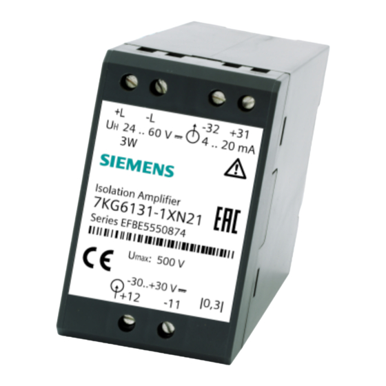
SIMEAS-T - Transducer with Auxiliary Power 2.1 Application range SIMEAS transducers for DC current or DC voltage with auxiliary power convert the input current or the input voltage into load-independent DC output current or load-independent DC output voltage. As long as the maximum permissible limit... -
Page 5: Working Principle
SIMEAS-T - Transducer with Auxiliary Power 2.3 Working principle Via resistors (1), the input voltage U is adapted to the pulse-pause-ratio voltage converter (2). The rectangular signal generated by this is transmitted via a transformer (3) to the output side, fi ltered and conditioned by the amplifi er (4). -
Page 6: Characteristic Curves
SIMEAS-T - Transducer with Auxiliary Power 2.5 Characteristic curves DC current and DC voltage A in mA -E -E -E -E A = output signal, DC (mA, V) = nominal output signal E = input signal, DC (mA, V) = nominal input signal... -
Page 7: General Remarks
If further information is required or if special problems occur which are not suffi ciently described in this document, please request the specifi c information from your local Siemens offi ce or contact one of the departments listed on the back cover of this manual. - Page 8 SIMEAS-T - Transducer with Auxiliary Power QUALIFIED PERSONNEL Grievous physical injury or damage may result if this appliance/system is interfered with by unqualifi ed persons or if the safety warnings in this manual are not heeded. Therefore, only suitably qualifi ed personnel may service this appliance/system.
-
Page 9: Technical Specifi Cations
SIMEAS-T - Transducer with Auxiliary Power 2.7 Technical specifi cations Input Only for connection to DC voltage systems with maximum nominal voltage of input 500/1000 V see 2.8 description DC voltage signal E or DC current I standard nominal current I 1 mA;... - Page 10 SIMEAS-T - Transducer with Auxiliary Power Auxiliary power U nominal input voltage U - DC voltage DC 24-60 V; 110-220 V - AC voltage AC 100; 115; 230 V; 45-65 Hz input range - DC voltage ± 20 % - AC voltage ±...
- Page 11 SIMEAS-T - Transducer with Auxiliary Power Other technical specifi cations surge voltage VDE 0435, Part 303 for type testing - input to output Ü = 5 kV, 1.2/50 µsec Ri = 500 Ω - input to auxiliary power Ü = 5 kV, 1.2/50 µsec Ri = 500 Ω...
-
Page 12: Description
SIMEAS-T - Transducer with Auxiliary Power 2.8 Description The transducers in their housing are permanently-wired and tested function units. They include snap-on mounting for a 35 mm top-hat rail according to DIN EN 50022. Inputs and outputs can be safely connected with screw terminals. -
Page 13: Ordering Data
SIMEAS-T - Transducer with Auxiliary Power Ordering data for DC voltage, DC current, isolation amplifi er Designation Designation Order-No. Order-No. Code Code 6 1 3 1 6 1 3 1 6 1 3 1 6 1 3 1 6 1 3 1... -
Page 14: Installation And Operation
SIMEAS-T - Transducer with Auxiliary Power 2.10 Installation and operation Í Í Í WARNING Certain parts of electrical appliances are inevitably under hazardous voltage during operation. Grievous physical injury or damage can occur if the operating instructions are not heeded. -
Page 15: Startup
SIMEAS-T - Transducer with Auxiliary Power 2.11 Startup Make sure that the operating data match the data given on the rating plate. Do not modify any transducer settings. The transducer is operational after a 15 minute warm-up period and will keep within the error tolerances. -
Page 16: Calibration And Testing
SIMEAS-T - Transducer with Auxiliary Power 2.13 Calibration and testing Í Í Í WARNING When carrying out these tasks, the provisions and instructions of the accident prevention regulations VBG 4.0 must be observed. Point 8 is of particular importance: “Permissible deviations while working on active parts“. Appropriate electrical tools are to be used. - Page 17 SIMEAS-T - Transducer with Auxiliary Power Test circuit for voltage and current transducers. 1. DC voltage sensor 0 to 1000 V or DC current sensor 0 to 30 mA 2. voltmeter, class 0.01 3. amperemeter, class 0.01, Ri ≤ 10 Ω...
- Page 18 SIMEAS-T - Transducer with Auxiliary Power Arrangement of the balance potentiometers and bridges on the measuring module. BR13.1 2 3 X14.2 1 R41 BR12 G34924-J1003-H2 BR11.1 2 3 current output BR13.1 – BR13.2: open BR13.2 – BR13.3: closed voltage output BR13.1 –...
- Page 19 SIMEAS-T - Transducer with Auxiliary Power Transducer with a linear characteristic input and output unipolar or input and output symmetrically bipolar BR11.1 – BR11.2 : open BR11.2 – BR11.3 : open BR12.1 – BR12.2 : open X14.1 – X14.2 : closed Zero adjustment Apply E = 0 ±...
- Page 20 SIMEAS-T - Transducer with Auxiliary Power Transducer with a linear characteristic input unipolar 0 bis +E output unipolar +4 mA to +20 mA BR11.1 – BR11.2 : open BR11.2 – BR11.3 : open BR12.1 – BR12.2 : closed Zero adjustment X14.1 –...
- Page 21 SIMEAS-T - Transducer with Auxiliary Power Transducer with a linear characteristic input unipolar +4 mA to + 20 mA output unipolar 0 to +A BR11.1 – BR 11.2 : closed BR11.2 – BR11.3 : open BR12.1 – BR 12.2 : open X14.1 –...
- Page 22 Bernd Müller Weissacher Straße 11 D-70499 Stuttgart E-Mail: [email protected] Tel.: + 49 ( 7 11) 137-61 01 Fax: + 49 ( 7 11) 137-60 90 Internet: http://www.siemens.de Siemens Aktiengesellschaft © Siemens AG 2006 All Rights Reserved Printed in Germany 08/2006...


