
Related Manuals for Siemens SICAM T 7KG966


Summary of Contents for Siemens SICAM T 7KG966
- Page 1 Multifunktionaler Messumformer SICAM T 7KG966 Produktinformation E50417-B1050-C493-A4...
- Page 2 Beachten Sie die Hinweise und Warnungen in diesem Doku- ment. Diese Produktinformation enthält wichtige Informationen zum SICAM T 7KG966. Sie ist Bestandteil des gelieferten Produkts. Angaben zur Konformität Das Produkt entspricht den Bestimmungen der Richtlinie des Rates der Europäischen Gemeinschaften zur Anglei- chung der Rechtsvorschriften der Mitgliedsstaaten über die...
-
Page 3: Table Of Contents
Verwendete Symbole Bestellinformationen Anwendung Aufbau Montage und Inbetriebnahme Anschlussarten 10 Gemessene und berechnete Größen 11 Schnittstellen 12 Abgleich 13 Batterieaustausch 14 LED-Meldungen 15 Fehlersuche, Instandsetzung, Reinigung 16 Lagerung und Transport 17 Technische Daten (Auswahl) SICAM T 7KG966, Betriebsanleitung E50417-B1050-C493-A4, Ausgabestand 12.2012... -
Page 4: Vorwort
Geschäftsbeziehung noch ändern sie diese ab. Alle Verpflichtungen der Siemens AG gehen aus den entsprechenden vertraglichen Vereinbarungen hervor. Die Siemens AG behält sich das Recht vor, dieses Dokument von Zeit zu Zeit zu ändern. Copyright Copyright © Siemens AG 2012. Alle Rechte vorbehal- ten. -
Page 5: Allgemeine Hinweise
Eingetragene Marken ® SICAM ist eine eingetragene Marke der Siemens AG. Jede nicht autorisierte Verwendung ist unzulässig. Alle anderen Beschreibungen in diesem Dokument bzw. in diesen Informationen können Marken enthal- ten, deren Verwendung durch Dritte für ihre eigenen Zwecke die Rechte des Eigentümers möglicherweise verletzen. -
Page 6: Hinweise Zu Ihrer Sicherheit
Es enthält jedoch Hin- weise, die Sie zu Ihrer persönlichen Sicherheit sowie zur Vermeidung von Sachschäden beachten müssen. Die Hinweise sind durch ein Warndreieck hervorgeho- ben und je nach Gefährdungsgrad wie folgt dargestellt: SICAM T 7KG966, Betriebsanleitung E50417-B1050-C493-A4, Ausgabestand 12.2012... - Page 7 Beachten Sie alle Hinweise, um Sachschäden zu vermeiden. HINWEIS ist eine wichtige Information über das Produkt, die Handhabung des Produktes oder den jeweiligen Teil der Dokumentation, auf den besonders aufmerksam gemacht werden soll. SICAM T 7KG966, Betriebsanleitung E50417-B1050-C493-A4, Ausgabestand 12.2012...
- Page 8 Das Betriebsmittel (Gerät, Baugruppe) darf nur für die im Katalog und der technischen Beschreibung vorge- sehenen Einsatzfälle und nur in Verbindung mit von Siemens empfohlenen bzw. zugelassenen Fremdge- räten und -komponenten verwendet werden. Wird das Gerät nicht gemäß dieser Produktinformation benutzt, ist der vorgesehene Schutz beeinträchtigt.
-
Page 9: Verwendete Symbole
Inbetriebnahme zu beachten. Verwendete Symbole Tabelle 4-1 Verwendete Symbole Symbol Beschreibung Gleichstrom IEC 60417-5031 Wechselstrom IEC 60417-5032 Drehstrom Erdungsanschluss IEC 60417-5017 Schutzleiterklemme IEC 60417-5019 Vorsicht, Risiko eines elektrischen Schlages Vorsicht, Risiko einer Gefahr ISO 7000-0434 SICAM T 7KG966, Betriebsanleitung E50417-B1050-C493-A4, Ausgabestand 12.2012... -
Page 10: Bestellinformationen
Messungen: U, I, f, P, Q, S, cos phi, Energie IEC 61850 AC-Eingangskreise Spannungsteiler Galvanisch isolierte Spannungseingänge DC-Analogausgänge Ohne 4 DC-Analogausgänge -20 mA bis 20 mA/-10 V bis 10 V Optionales Zubehör ist im Gerätehandbuch aufgelistet. SICAM T 7KG966, Betriebsanleitung E50417-B1050-C493-A4, Ausgabestand 12.2012... -
Page 11: Anwendung
Anwendung Der Multifunktionale Messumformer SICAM T 7KG966 ist ein Gerät zur Erfassung von Messwerten in Energie- versorgungsnetzen. Er wird in Einphasennetzen sowie in 3-Leiter- und 4-Leiternetzen eingesetzt. Für Messungen werden den AC-Eingängen Wechsel- größen von Strom und Spannung zugeführt. Ohne Ver- wendung von externen Spannungs- und Stromwand- lern können Nenneingangswechselspannungen bis... -
Page 12: Aufbau
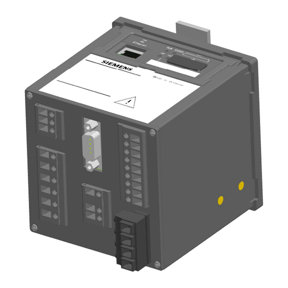
Ausgänge Klemmen für Versorgungsspannung und Schutzleiter Bild 7-1 Klemmenseite, SICAM T 7KG966 mit RS485 Auf der Geräteoberseite befinden sich der Ethernet- Steckverbinder RJ45 mit 2 LEDs und 4 weitere LEDs. Am Batteriefachdeckel befinden sich ein Beschriftungs- feld für die parametrierbaren LEDs H1/H2/ERROR und ein Batteriesymbol mit der Darstellung der Batteriepo- larität. - Page 13 Taster Default IP Address : 192. 168.0.55 Default Subnet Mask : 255.255 .255.0 Bild 7-2 Hutschienenseite des SICAM T 7KG966 Auf der Hutschienenseite ist mittig die Hutschienenhal- terung befestigt. Außerdem befindet sich im rechten unteren Teil der IP-Addr.-Taster, mit dem per Knopf- druck (>...
-
Page 14: Montage Und Inbetriebnahme
2,5 mm² ausgelegt. Das Gerät darf während des Betriebes keiner Kon- densation ausgesetzt werden. Platzieren Sie das Gerät so, dass es keiner direkten Sonneneinstrahlung und keinem starken Tempera- turwechsel ausgesetzt ist. SICAM T 7KG966, Betriebsanleitung E50417-B1050-C493-A4, Ausgabestand 12.2012... - Page 15 2. Schieben Sie das Gerät mit der Führung des Hut- schienen-Clips auf eine Seite der Hutschiene. 3. Schieben Sie das Gerät auf der Hutschiene an die gewünschte Position. 4. Lassen Sie die Entriegelung los. Das Gerät ist nun auf der Hutschiene fixiert. SICAM T 7KG966, Betriebsanleitung E50417-B1050-C493-A4, Ausgabestand 12.2012...
- Page 16 Trennvorrichtung für das Gerät gekennzeichnet sein. Sichern Sie die Versorgungsspannung mit einer UL/IEC- zugelassenen Sicherung: 1,6 A, Typ C. Wenn Sie eine Schmelzsicherung verwenden, müssen Sie hierfür auch einen UL/IEC-zugelassenen Siche- rungshalter verwenden. SICAM T 7KG966, Betriebsanleitung E50417-B1050-C493-A4, Ausgabestand 12.2012...
- Page 17 Die Polarität und die Phasenzuordnung an den Mess- wandlern sind durch Sie zu überprüfen. Siemens empfiehlt Ihnen, das Gerät mindestens 2 Stun- den im Betriebsraum liegen zu lassen, bevor Sie es in Be-trieb nehmen, um einen Temperaturausgleich zu schaffen und um Feuchtigkeit sowie Kondensation zu vermeiden.
- Page 18 Diese wird isoliert im Batteriefach des Gerätes ausgeliefert. 1. Hebeln Sie mit einem geeigneten Werkzeug (z.B. Feinmechaniker-Schraubendreher 2,0 mm) den Batteriefachdeckel aus der Fassung. Batteriefach- deckel Polaritäts- angabe der Batterie Typenschild Bild 8-2 Geräteoberseite SICAM T 7KG966, Betriebsanleitung E50417-B1050-C493-A4, Ausgabestand 12.2012...
-
Page 19: Anschlussarten
Die Parametrierung ist im Gerätehandbuch, Bestell- nummer E50417-H1000-C493, beschrieben. Anschlussarten Die folgenden Eingangsbeschaltungen sind Beispiele. SICAM T 7KG966 kann bis zu den maximal zulässigen Strom- und Spannungswerten (siehe Kapitel 17.1) auch ohne zwischengeschaltete Strom- oder Span- nungswandler angeschlossen werden. Erforderliche Spannungswandler können in Stern- oder Dreieckschaltung betrieben werden. - Page 20 Beachten Sie bei den Schaltungen 9.1, 9.4 und 9.5 die Einsatzbedingungen gemäß Kapitel 6 im Gerätehand- buch. HINWEIS Bei SICAM T 7KG966x-2xAx0-xAA0 ist in der Schal- tung 9.2 die elektrische Verbindung PE-N nicht zwin- gend erforderlich. SICAM T 7KG966, Betriebsanleitung E50417-B1050-C493-A4, Ausgabestand 12.2012...
- Page 21 Die Sekundärspannung am Anschluss F (Voltage) darf AC 480 V (max. AC 347 V für UL) nicht überschreiten. Es können Sachschäden entstehen. Achten Sie darauf, dass die maximal zulässige Span- nung Leiter - Erde (PE) nicht überschritten wird. SICAM T 7KG966, Betriebsanleitung E50417-B1050-C493-A4, Ausgabestand 12.2012...
- Page 22 AC 480 V (max. AC 347 V für UL) nicht überschreiten. Es können Sachschäden entstehen. Achten Sie darauf, dass die maximal zulässige Spannung Leiter - Erde (PE) nicht überschritten wird. Beispiel: 4-Leiternetz, gleiche Belastung Klemmen am SICAM T 10 A SICAM T 7KG966, Betriebsanleitung E50417-B1050-C493-A4, Ausgabestand 12.2012...
- Page 23 10 A Beispiel: 4-Leiternetz, beliebige Belastung Klemmen am SICAM T je 10 A HINWEIS Außer den in dieser Produktinformation enthaltenen Schaltungsbeispielen sind im Gerätehandbuch SICAM T 7KG966, Bestellnummer E50417-H1000- C493, weitere Anschlussbeispiele aufgeführt. SICAM T 7KG966, Betriebsanleitung E50417-B1050-C493-A4, Ausgabestand 12.2012...
-
Page 24: Gemessene Und Berechnete Größen
L1, L2, L3, Σ ±1 % Phasenwinkel Φ L1, L2, L3, Σ ±2° Netzfrequenz f L1-N siehe L1, L2, L3, Σ Wirkenergie WP Bezug ±0,5 % Wirkenergie WP Lieferung L1, L2, L3, Σ ±0,5 % SICAM T 7KG966, Betriebsanleitung E50417-B1050-C493-A4, Ausgabestand 12.2012... - Page 25 Messbereich (siehe Referenzbedingun- gen Kapitel 17.4) Die Genauigkeit der Frequenzmessung ist je nach Gerätetyp und Spannung unterschiedlich und liegt zwischen 10 mHz und 40 mHz. Detaillierte Anga- ben sind im Gerätehandbuch SICAM T 7KG966 beschrieben. SICAM T 7KG966, Betriebsanleitung E50417-B1050-C493-A4, Ausgabestand 12.2012...
-
Page 26: Schnittstellen
Leiterquerschnitt mit Aderendhülse 1,5 mm² mit Aderendhülse (Klemme F) 2,5 mm² Anzugsmoment 0,4 Nm bis 0,5 Nm RS485-Schnittstelle (J) auf der Klemmenseite: RS485-Kabel mit Steckverbinder Ethernet-Schnittstelle (Z) auf der Oberseite: Ethernet-Patch-Kabel mit Steckverbinder SICAM T 7KG966, Betriebsanleitung E50417-B1050-C493-A4, Ausgabestand 12.2012... - Page 27 GEFAHR Gefahr durch hohe Berührungsspannungen Nichtbeachtung hat Tod oder schwere Körperver- letzung zur Folge. Die Erdung müssen Sie am SICAM T 7KG966 immer an der Schutzleiterklemme (Klemmenblock H) anschließen. Wenn Sie die DC-Analogausgänge (K1 bis K9) nut- zen, müssen Sie die Funktionserde an der Klemme K1 anschließen.
- Page 28 K: 8/9 z.B. 1x Strom und 3x Spannung Ethernet- Ethernet-Anschluss; auf der Schnittstelle Oberseite des Gehäuses Nur bei Gerätevarianten, die über eine RS485- Schnittstelle verfügen Nur bei Gerätevarianten, die über DC-Analog- ausgänge verfügen SICAM T 7KG966, Betriebsanleitung E50417-B1050-C493-A4, Ausgabestand 12.2012...
-
Page 29: Abgleich
Betriebsdauer nicht erneut abgeglichen zu werden. Der Abgleich erfolgt ausschließlich bei betriebsinternem Bedarf. Eine ausführliche Beschreibung des Geräteabgleichs finden Sie im Gerätehandbuch des SICAM T 7KG966, Bestellnummer E50417-H1000-C493. SICAM T 7KG966, Betriebsanleitung E50417-B1050-C493-A4, Ausgabestand 12.2012... -
Page 30: Batterieaustausch
Werfen Sie die Batterie nicht in das Feuer. Setzen Sie die Batterie keinen Temperaturen über 100 °C aus. Versuchen Sie nicht, die Batterie aufzuladen. Verhindern Sie den Zugriff von Kindern auf die Lithium-Batterie. SICAM T 7KG966, Betriebsanleitung E50417-B1050-C493-A4, Ausgabestand 12.2012... - Page 31 Seite. 4. Entnehmen Sie die neue Batterie des Typs PANASONIC CR2032 oder VARTA 6032 101 501 der Verpackung (auf der Verpackung aufgedrucktes Verbrauchsdatum beachten). 5. Setzen Sie die Batterie vorsichtig unter Beachtung SICAM T 7KG966, Betriebsanleitung E50417-B1050-C493-A4, Ausgabestand 12.2012...
- Page 32 Die im Gerät befindliche Batterie enthält Lithium und darf nur durch Fachpersonal ausgewechselt und durch entsprechende Recyclingbetriebe entsorgt werden. Werfen Sie die Batterie nicht in den Abfall. Bei der Entsorgung der Batterie sind die nationalen und internationalen Bestimmungen einzuhalten. SICAM T 7KG966, Betriebsanleitung E50417-B1050-C493-A4, Ausgabestand 12.2012...
-
Page 33: Led-Meldungen
LED-Meldungen SICAM T 7KG966 überwacht automatisch die Funktio- nen seiner Hardware-/Software-/Firmware-Kompo- nenten. Die LEDs auf der Oberseite des Gehäuses signalisieren den aktuellen Gerätezustand. Bezeichnung der LEDs ERROR Speed Link/ Activity Bild 14-1 Bezeichnung der LEDs Bedeutung der LEDs LED (grün, rot, gelb): ein LED (grün, rot, gelb): blinkt... - Page 34 Boot-Programm ist gestartet, nachdem der ERROR IP-Addr.-Tastschalter während des Einschaltens der Versorgungsspannung gedrückt wurde. ERROR DHCP aktiv (H1 schaltet aus nach Empfang der IP-Adresse über DHCP) ERROR Default-IP-Adresse durch Drücken des IP-Addr.-Tastschalters SICAM T 7KG966, Betriebsanleitung E50417-B1050-C493-A4, Ausgabestand 12.2012...
- Page 35 DHCP aktiv (H1 schaltet aus nach Empfang der IP-Adresse über ERROR DHCP) Boot-Programm gestartet, ERROR Prozessapplikation wird geladen. Doppelte IP-Adresse wurde erkannt. ERROR Prozessapplikation Normaler Betrieb ERROR Nutzung der parametrierten IP-Adresse oder IP-Adresse über DHCP bezogen. SICAM T 7KG966, Betriebsanleitung E50417-B1050-C493-A4, Ausgabestand 12.2012...
-
Page 36: Fehlersuche, Instandsetzung, Reinigung
Gerät ins Herstellerwerk einzusenden. Hierzu verwenden Sie möglichst die Original-Trans- portverpackung oder eine gleichwertige Verpackung. Reinigung: Schalten Sie das Gerät aus. Wischen Sie es mit einem sauberen, trockenen und weichen Tuch ab. Verwenden Sie keine Lösungsmittel. SICAM T 7KG966, Betriebsanleitung E50417-B1050-C493-A4, Ausgabestand 12.2012... -
Page 37: Lagerung Und Transport
-25 °C bis +70 °C. Die relative Luft- feuchte darf weder zur Kondenswasser- noch zur Eis- bildung führen. Siemens empfiehlt Ihnen, bei der Lagerung einen ein- geschränkten Temperaturbereich zwischen +10 °C und +35 °C einzuhalten, um einer vorzeitigen Alterung der eingesetzten Elektrolytkondensatoren vorzubeugen. -
Page 38: Technische Daten (Auswahl)
Technische Daten (Auswahl) HINWEIS Weitere Angaben zu den technischen Daten sind im Gerätehandbuch SICAM T 7KG966, Bestellnummer E50417-H1000-C493, enthalten. 17.1 Eingänge Eingänge für Wechselspannungsmessungen Nenneingangsspannungen 63,5 V (L-N/PE) 110 V 230 V 400 V (max. 347 V für UL) Maximale Messspannung L-N/PE 480 V (max. - Page 39 Pulsstrom für 0,1 s 300 mA 35 Ω Innenwiderstand zulässige Schaltfrequenz 10 Hz DC-Analogausgänge Ansprechzeit 100 ms Nutzung als Stromausgänge (DC) Nennausgangsstrom ±20 mA maximaler Ausgangsstrom ±24 mA < 400 Ω maximaler Lastwiderstand SICAM T 7KG966, Betriebsanleitung E50417-B1050-C493-A4, Ausgabestand 12.2012...
- Page 40 DC 700 V Kat. III Schnittstelle 17.4 Genauigkeitsangaben unter Referenzbedingungen (Genauigkeitsangaben unter Referenzbedingungen) Eingangsstrom Nennstrom ± 1 % Eingangsspannung Nennspannung ± 1 % Frequenz 45 Hz bis 65 Hz Sinus, Klirrfaktor ≤ 5 % Kurvenform SICAM T 7KG966, Betriebsanleitung E50417-B1050-C493-A4, Ausgabestand 12.2012...
- Page 41 9-poliger D-SUB- Steckverbinder Busprotokoll Modbus RTU Baud-Rate 1200 Bit/s 2400 Bit/s 4800 Bit/s 9600 Bit/s 19 200 Bit/s 38 400 Bit/s 57 600 Bit/s 115 200 Bit/s Protokoll Halbduplex Max. Kabellänge 1000 m SICAM T 7KG966, Betriebsanleitung E50417-B1050-C493-A4, Ausgabestand 12.2012...
- Page 42 Maximale Leistungsaufnahme 5 W/16 VA 17.8 Batterie Typen PANASONIC CR2032 VARTA 6032 101 501 Spannung Kapazität 230 mAh Typische Lebensdauer bei ständig angelegter Versorgungsspannung 10 Jahre bei nicht ständig angelegter Versorgungsspannung 2 Monate innerhalb von 10 Jahren SICAM T 7KG966, Betriebsanleitung E50417-B1050-C493-A4, Ausgabestand 12.2012...
- Page 43 17.10 Zusätzliche technische Daten Interne Sicherung nicht austauschbar Typ T1.6A/250V gemäß IEC 60127 Interne Sicherung, sekundär nicht austauschbar Typ F2A/125V gemäß UL 248-14 17.11 Schutzklasse gemäß IEC 60529 Klemmenseite IP20 Hutschienenseite IP20 Oberseite IP20 SICAM T 7KG966, Betriebsanleitung E50417-B1050-C493-A4, Ausgabestand 12.2012...
- Page 44 17.12 Maße Masse ca. 0,5 kg Abmessungen (B x H x T) 96 mm x 96 mm x 100 mm 111,3 103,8 Maßangabe in mm Bild 17-1 Abmessungen SICAM T 7KG966, Betriebsanleitung E50417-B1050-C493-A4, Ausgabestand 12.2012...
- Page 45 Multifunctional Transducer SICAM T 7KG966 Product Information E50417-B1050-C493-A4...
- Page 46 Observe the Notes and Warnings for your own safety in this document. This Product Information contains important information about the SICAM T 7KG966 and is part of the product delivery. Statement of Conformity This product complies with the directive of the Council of the...
- Page 47 Connection Types 10 Measurands and Calculation of Measurands 24 11 Interfaces 12 Calibration 13 Replacing the Battery 14 LED Indications 15 Troubleshooting, Repair, Cleaning 16 Storage and Transport 17 Technical Data (Selection) SICAM T 7KG966, Product Information E50417-B1050-C493-A4, Edition 12.2012...
-
Page 48: Preface
Although Siemens AG has made best efforts to keep the document as precise and up-to-date as possible, Siemens AG shall not assume any liability for defects and damage which result through use of the information contained herein. -
Page 49: General Information
Registered Trademarks ® SICAM is a registered trademark of Siemens AG. An unauthorized use is illegal. All other designations in this document can be trademarks whose use by third parties for their own purposes can infringe the rights of the owner. -
Page 50: Information For Your Safety
Chapter 1. If you have any questions about the device, please con- tact our Siemens sales partner responsible in your region. Our Energy Customer Support Center is available to you twenty-four hours a day. - Page 51 Follow all advice instructions to prevent damage to property. NOTE is important information about the product, the handling of the product, or the part of the documentation in question to which special attention must be paid SICAM T 7KG966, Product Information E50417-B1050-C493-A4, Edition 12.2012...
- Page 52 Even after the supply voltage has been discon- nected, hazardous voltages can still be present in the equipment (capacitor storage). Equipment with current transformer circuits must not SICAM T 7KG966, Product Information E50417-B1050-C493-A4, Edition 12.2012...
-
Page 53: Used Symbols
Direct current IEC 60417-5031 Alternating current IEC 60417-5032 Three-phase alternating current Erarth (ground) terminal IEC 60417-5017 Protective conductor terminal IEC 60417-5019 Caution, risk of electric shoc Caution, risk of danger ISO 7000-0434 SICAM T 7KG966, Product Information E50417-B1050-C493-A4, Edition 12.2012... -
Page 54: Ordering Information
AC input circuits Resistive divider Galvanic isolated voltage transformers DC analog outputs Without 4 DC analog outputs -20 mA to 20 mA/-10 V to 10 V Optional accessories are listed in the device manual. SICAM T 7KG966, Product Information E50417-B1050-C493-A4, Edition 12.2012... -
Page 55: Application
Application The Multifunctional Transducer SICAM T 7KG966 is used for the acquisition of measured values in power supply systems. It is used in 1-phase systems, in 3-wire and 4-wire systems. The measurements are obtained from the alternating quantities of current and voltage supplied to the AC inputs. -
Page 56: Design
Figure 7-1 Terminal Side, SICAM T 7KG966 with RS485 The top side of the device accommodates the RJ45 Ethernet connector with 2 LEDs and 4 additional LEDs. At the cover of the battery compartment there is a labelling strip for the configurable LEDs H1/H2/ERROR and a battery symbol that indicates the polarity. - Page 57 Default IP Address : 192.168.0.55 Default Subnet Mask : 255.255 .255.0 Figure 7-2 DIN Rail Side of SICAM T 7KG966 The snap-on unit is mounted in the center of the DIN rail side. The IP-Addr. push-button is located in the lower right part.
-
Page 58: Mounting And Commissioning
2.5 mm² max. (AWG 14). The device must not be exposed to condensation during operation. The device must be installed in a location where it is not exposed to direct sunlight and strong temperature variations. SICAM T 7KG966, Product Information E50417-B1050-C493-A4, Edition 12.2012... - Page 59 DIN rail. 3. Move the device into the desired position on the DIN rail. 4. Release the release device. The device is now firmly mounted on the DIN rail. SICAM T 7KG966, Product Information E50417-B1050-C493-A4, Edition 12.2012...
- Page 60 Secure the supply voltage with an approved (UL/IEC) fuse: 1.6 A, type C. If a melting fuse is used, a suitable approved (UL/IEC) fuse holder has to be used. SICAM T 7KG966, Product Information E50417-B1050-C493-A4, Edition 12.2012...
- Page 61 IT networks to pick up. Make sure that the maximum allowable voltage at the inputs of SICAM T 7KG966 to ground V = 480 V (max. 347 V for UL) is not...
- Page 62 1. Lever the cover of the battery compartment out of the socket with a suitable tool (e.g. precision engineer screwdriver 2.0 mm). Cover of battery compartment Polarity of the battery Type plate Figure 8-2 Device Top Side SICAM T 7KG966, Product Information E50417-B1050-C493-A4, Edition 12.2012...
-
Page 63: Connection Types
Connection Types The following input wiring diagrams are examples. Up to the maximum allowable current and voltage values (see Chapter 17.1) SICAM T 7KG966 can also be connected without interconnected current and voltage transformers. Required voltage transformers can be operated in star connection or delta connection. - Page 64 Take into account the operating conditions at the cir- cuits 9.1, 9.4 and 9.5 in accordance with chapter 6 in the device manual. NOTE For SICAM T 7KG966x-2xAx0-xAA0, the electrical con- nection PE-N is not mandatory for the circuit 9.2. SICAM T 7KG966, Product Information E50417-B1050-C493-A4, Edition 12.2012...
- Page 65 The secondary voltage on terminal F (voltage) must not exceed AC 480 V (max. AC 347 V for UL). This could cause material damage. Please make sure that the maximum permissible voltage on conductor - ground (PE) is not exceeded. SICAM T 7KG966, Product Information E50417-B1050-C493-A4, Edition 12.2012...
- Page 66 AC 480 V (max. AC 347 V for UL). This could cause material damage. Please make sure that the maximum permissible voltage on conductor - ground (PE) is not exceeded. Example: 4-wire System, Balanced Terminals SICAM T 10 A SICAM T 7KG966, Product Information E50417-B1050-C493-A4, Edition 12.2012...
- Page 67 Example: 4-wire System, Unbalanced Terminals SICAM T resp. 10 A NOTE The SICAM T 7KG966 device manual, order number E50417-H1040-C493, provides more circuit examples in addition to the ones shown in these Product Information. SICAM T 7KG966, Product Information E50417-B1050-C493-A4, Edition 12.2012...
-
Page 68: Measurands And Calculation Of Measurands
±1 % Phase angle Φ a, b, c, Σ ±2° Frequency f a, b, c, Σ Active energy WP demand ±0.5 % a, b, c, Σ Active energy WP supply ±0.5 % SICAM T 7KG966, Product Information E50417-B1050-C493-A4, Edition 12.2012... - Page 69 (see reference conditions Chapter 17.4) The accuracy of the frequency measurement dif- fers according to device type and voltage and ranges between 10 mHz and 40 mHz. The SICAM T 7KG966 device manual provides detailed information. SICAM T 7KG966, Product Information E50417-B1050-C493-A4, Edition 12.2012...
-
Page 70: Interfaces
0.4 Nm to 0.5 Nm (3.5 in-lb to 4.5 in-lb) RS485 interface (J) on the terminal side: RS485 cable with plug connector Ethernet interface (Z) on the top side: Ethernet patch cable with plug connector SICAM T 7KG966, Product Information E50417-B1050-C493-A4, Edition 12.2012... - Page 71 DANGER Danger due to high voltages Non-observance will lead to death or serious injury. The grounding on the SICAM T 7KG966 always has to be connected to the protective conductor terminal (terminal block H). If you are using the DC analog outputs (K1 to K9), you have to connect the functional grounding terminal K1.
- Page 72 1 x current and 3 x voltage Ethernet Ethernet connection; on the top interface side of the housing Only for device variants which have a RS485 interface Only for device variants which have analog outputs SICAM T 7KG966, Product Information E50417-B1050-C493-A4, Edition 12.2012...
-
Page 73: Calibration
The calibration is only carried out if necessary due to internal requirements. For a detailed description of the device calibration, see the device manual of SICAM T 7KG966, order number E50417-H1040-C493. SICAM T 7KG966, Product Information E50417-B1050-C493-A4, Edition 12.2012... -
Page 74: Replacing The Battery
Caution: The battery used in this device may present a fire or chemical burn hazard if mistreated. Do not recharge, disassemble, heat above 100 °C (212 °F) or incinerate. Dispose of used battery promptly. Keep away from chil- dren. SICAM T 7KG966, Product Information E50417-B1050-C493-A4, Edition 12.2012... - Page 75 4. Remove the new battery type PANASONIC CR2032 or VARTA 6032 101 501 from the packaging (check the expiry date on the packaging) 5. Insert the battery carefully into the battery compartment with the polarity indicated above the SICAM T 7KG966, Product Information E50417-B1050-C493-A4, Edition 12.2012...
- Page 76 Do not dispose of the battery in the regular household waste. The national and international regulations must be observed when disposing of the battery. SICAM T 7KG966, Product Information E50417-B1050-C493-A4, Edition 12.2012...
-
Page 77: Led Indications
LED Indications SICAM T 7KG966 automatically monitors the functions of its hardware, software and firmware components. The LEDs on the top side of the housing indicate the current device status. Designation of the LEDs ERROR Link / Speed Activity Figure 14-1 Designation of the LEDs... - Page 78 Boot loader started after IP-Addr. push- ERROR button was pressed during power-on ERROR DHCP active (H1 switches off after reception of the IP address via DHCP) ERROR Default IP address by pressing the IP-Addr. push-button SICAM T 7KG966, Product Information E50417-B1050-C493-A4, Edition 12.2012...
- Page 79 IP address via ERROR DHCP) Boot loader started, process application is ERROR being loaded. Double IP address detected. ERROR Process Application Normal operation ERROR IP address as configured or obtained by DHCP. SICAM T 7KG966, Product Information E50417-B1050-C493-A4, Edition 12.2012...
-
Page 80: Troubleshooting, Repair, Cleaning
Furthermore, hazardous voltages can lead to lethal injuries when the work is performed improperly. If you suspect that the device has a defect, Siemens recommends to send the entire device back to the manufacturer. If possible, use the original transport packaging or an equivalent packaging. -
Page 81: Storage And Transport
+10 °C to +35 °C (+50 °F to +95 °F). If the device is stored for an extended period of time, Siemens recommend to connect the device to the supply voltage for 1 or 2 days once a year to reform the electrolytic capacitors in the device. -
Page 82: Technical Data (Selection)
Technical Data (Selection) NOTE For more information about the technical data, see the Device Manual SICAM T 7KG966, order number E50417-H1040-C493. 17.1 Inputs Inputs for alternating voltage measurements Rated input voltages 63.5 V (ph-N/PE) 110 V 230 V 400 V (max. 347 V... - Page 83 Admissible contact frequency 10 Hz DC analog outputs Pickup time 100 ms Use as current outputs (DC) Rated output current ±20 mA Maximum output current ±24 mA < 400 Ω Maximum load impedance SICAM T 7KG966, Product Information E50417-B1050-C493-A4, Edition 12.2012...
- Page 84 17.4 Precision specifications under reference condi- tions Input current Rated current ± 1 % Input voltage Rated voltage ± 1 % Frequency 45 Hz to 65 Hz sine, distortion factor ≤ 5 % Curve shape SICAM T 7KG966, Product Information E50417-B1050-C493-A4, Edition 12.2012...
- Page 85 Bus protocol Modbus RTU Baud rate 1200 bit/s 2400 bit/s 4800 bit/s 9600 bit/s 19 200 bit/s 38 400 bit/s 57 600 bit/s 115 200 bit/s Protocol half-duplex Max. cable length 1000 m SICAM T 7KG966, Product Information E50417-B1050-C493-A4, Edition 12.2012...
- Page 86 Types PANASONIC CR2032 VARTA 6032 101 501 Voltage Capacity 230 mAh Typical life time at permanently available power supply 10 years at not permanently available power supply 2 month within 10 years SICAM T 7KG966, Product Information E50417-B1050-C493-A4, Edition 12.2012...
- Page 87 IEC 60127 Internal fuse, secondary not replaceable type F2A/125V acc. to UL 248-14 17.11 Protection class according to IEC 60529 Terminal side IP20 DIN rail side IP20 Top side IP20 SICAM T 7KG966, Product Information E50417-B1050-C493-A4, Edition 12.2012...
- Page 88 Dimensions (W x H x D) 96 mm x 96 mm x 100 mm 3.78 inch x 3.78 inch x 3.94 inch 111.3 (4.38) 103.8 (4.09) Dimensions in mm (inch) Figure 17-1 Dimensions SICAM T 7KG966, Product Information E50417-B1050-C493-A4, Edition 12.2012...