
Related Manuals for Honeywell LT-32


Summary of Contents for Honeywell LT-32
- Page 1 Fire Alarm Control Panel LT-32 / LT-159 Installation and User Manual M-168.1-SERIE-LT-EN / 08.2022...
- Page 2 This documentation is subject to the copyright of Honeywell. The content must not be copied, published, modified, distributed, transmitted, sold or changed without the express prior written permission of Honeywell.
-
Page 3: Table Of Contents
Fire Alarm Control Panel LT-32 / LT-159 Contents General / Application ......................................................................5 Precautions .......................................................................... 6 CE marking and information ................................................................... 7 National Standards ......................................................................7 Transport damage inspection ..................................................................8 Pre-installation check list ................................................................... 9 Installation Overview ......................................................................10 Specifications ........................................................................... - Page 4 Fire Alarm Control Panel LT-32 / LT-159 Program menu ......................................................................... 32 13.1 Configuration – access to menu..............................................................33 13.2 Configuration - date and time setting ............................................................. 34 13.3 Configuration – panel configuration ............................................................36 13.4 Configuration – autolearn ................................................................39 13.5...
-
Page 5: General / Application
Fire Alarm Control Panel LT-32 / LT-159 GENERAL / APPLICATION The purpose of this manual is to provide the user with instructions concerning installation, use and maintenance of the LT-32 / LT-159 Fire Alarm Control Panel (FACP). SYSTEM EQUIPMENT The analogue-addressable LT-32 / LT-159 FACP is compact in size and very easy to install and configure. The system is specifically designed for Agile wireless equipments. -
Page 6: Precautions
Peripheral devices (sensors, etc.) which are not perfectly compatible with the control unit may cause damage to the control unit or cause the system to malfunction at any time. It is therefore essential to only use material which is guaranteed by Honeywell and is compatible with its control units. -
Page 7: Ce Marking And Information
Fire Alarm Control Panel LT-32 / LT-159 1.2 CE marking and information This document is a declaration that the products listed below conform to the essential protection requirements of the following European Directives: • RoHS - Restrictions on the Use of Certain Hazardous Substances in Electrical and Electronic Equipment •... -
Page 8: Transport Damage Inspection
It is important to check all supplied equipment for damage before proceeding with the installation! Before attempting to install the LT-32 / LT-159 control panel, or other equipment, you must do the following: 1. After removing the FACP, modules and other related equipments from... -
Page 9: Pre-Installation Check List
2.1 Pre-installation check list Before installing the LT-32 / LT-159 FACP you must first ensure that the following criteria have been met. Failure to do this, may not only result in damage to the equipment but may also cause problems during commissioning operations, or adversely affect its performance: •... -
Page 10: Installation Overview
Fire Alarm Control Panel LT-32 / LT-159 INSTALLATION OVERVIEW The panel range is designed for mounting onto an internal wall of a protected building, and is not suitable for mounting on outdoor applications. 1. Install the panel enclosure in accordance with the instructions reported in this manual. -
Page 11: Specifications
AC power supply with different plug options with a maximum rate power of 24 W • Autonomy in standby and alarm time, in absence of main power, are based on the system configuration. Please refer to Honeywell Loop Calculator for more details •... -
Page 12: Mechanical Specifications
Central entry prepared for 60 mm universal flush box • External connections: Removable Terminals for cables 0,5 mm • Housing color: LT-32 -> RAL 9002 / LT-159 -> RAL 9005 • Material: ABS flame retardant UL94 class V-0 • Weight: 400 g (incl. 6 batteries) Fig. -
Page 13: Electrical Specifications
Power connection terminal: European standard AC. UK connector optional • Maximum power consumption: 24 W • Supervised sounder outputs (1 in the LT-159, 2 in the LT-32), each with max. 50 mA • Max. 500 m distance depending on the cable section and current consumption in alarm •... -
Page 14: Panel Parts - Front View
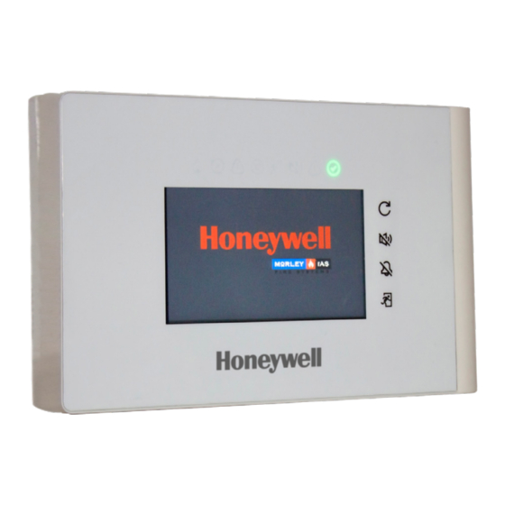
Fire Alarm Control Panel LT-32 / LT-159 PANEL PARTS – FRONT VIEW Fig. 6: Front view LED Indicators Functional Buttons Touch Display M-168.1-SERIE-LT-EN / 08.2022... -
Page 15: Panel Parts - Internal View
Fire Alarm Control Panel LT-32 / LT-159 5.1 Panel parts – internal view Fig. 7: Internal view Front Cover Buzzer LED Indicators USB Port B Type Display Batteries Location Fault Contact Jumper Rear Cover Alarm Contact Jumper Cable Entry Holes... - Page 16 Fire Alarm Control Panel LT-32 / LT-159 Fig. 8: Power Supply and Batteries Batteries used within this product may only be replaced by batteries that are in compliance with IEC 60896-11, IEC 60896-21, IEC 60896-22, IEC 61056-1 and IEC 61056-2 or IEC 62485-2 and made of material with flammability rating V-1 or better.
-
Page 17: Panel Installation
Fire Alarm Control Panel LT-32 / LT-159 PANEL INSTALLATION The equipment must be installed indoors, with requirements refer chapter 4.3. The installation of the panel must be carried out by qualified personnel. The electronic components that make up of the equipment, are vulnerable to physical damage or electrostatic discharge. -
Page 18: Surface Mounting
6.1 Surface mounting The LT-32 / LT-159 FACP can be surface mounted onto a flat wall, using suitable fixtures and fittings (height between 80 … 170 cm). As a general recommendation for type of wall surfaces, ensure assessments are made and suitable fixtures and fittings are used to hold the panel assembly. The panel backbox is mounted on a concrete block wall. -
Page 19: Cabling
Fire Alarm Control Panel LT-32 / LT-159 CABLING All wiring must comply with local regulations. Also observe the requirements for cabling and interconnection of a fire detection and alarm system. For information on how to wiring compatible field devices, please refer to the related product documentation. - Page 20 Fire Alarm Control Panel LT-32 / LT-159 QUALITY OF CABLE It is vitally important that good quality cable is used and that correct installation techniques are followed. In general, the following cable installation requirements must be met: All cable sections must be circular to allow effective cable clamping using the cable glands.
-
Page 21: Cable Routing And Connections
Fire Alarm Control Panel LT-32 / LT-159 7.1 Cable routing and connections Remove the keyholes and pass the cables through them. LT-32 Ref. Description LT-159 Ref. Description Fault NO/NC Fault NO/NC Fault C Fault C Alarm NO/NC... - Page 22 LT-159 requires a closed loop: connectors J12 and J11 are used to connect side “A” and side “B” of the loop. SOUNDER CONNECTION LT-32 is equipped with two sounder outputs: OUT 1 and OUT 2 balanced with diodes provided with the panel. LT-159 is equipped with one sounder output: OUT 1balanced with a diode provided with the panel.
-
Page 23: Setup And Connections Overview
Fire Alarm Control Panel LT-32 / LT-159 7.2 LT-32 setup and connections overview Relay Setup Sounder 2 + Sounder 2 - Sounder 1 + Sounder 1 - Batteries connected in two rows with polarity as shown. -
Page 24: 159 Setup And Connections Overview
Fig. 17: LT-159 setup and connections overview • When the front cover is opened a tamper fault is reported. Fault is reset automatically once the cover is closed again. • The connections shown have the purpose to underline the differences with LT-32. M-168.1-SERIE-LT-EN / 08.2022... -
Page 25: Detectors And Modules Overview
Fire Alarm Control Panel LT-32 / LT-159 DETECTORS AND MODULES OVERVIEW A Detector device such as a Smoke or Heat detector: • Has a given a unique "Address“ • Can be given a location label of up to 20 characters •... -
Page 26: Display And Controls
Fire Alarm Control Panel LT-32 / LT-159 DISPLAY AND CONTROLS The touch screen display and LED indications, allow the user to review the system status and, with appropriate user PIN, have access and perform tasks in accordance with the requirements of the local fire regulations. There are 8 status icons provided on the front panel and 4 push buttons for event conditions. - Page 27 Fire Alarm Control Panel LT-32 / LT-159 PUSH BUTTON DESCRIPTION FUNCTION RESET PANEL Pressing the ‘Reset Panel’ button will reset the panel to return it to normal condition after an event MUTE Pressing the ‘Mute’ button or tapping on the touch screen, will silence the active panel buzzer SILENCE SOUNDERS Pressing the ‘Silence Sounders’...
-
Page 28: System Default Password
Fire Alarm Control Panel LT-32 / LT-159 10 SYSTEM DEFAULT PASSWORD PASSWORD ENTRY When a function is protected by password, the below screens appear, indicating the Level required. Using the virtual keyboard, insert the password and confirm with enter: Fig. 18: Screen ... -
Page 29: Display Overview
Fire Alarm Control Panel LT-32 / LT-159 11 DISPLAY OVERVIEW The status of the unit and its connected devices is shown on the display. The display is turned off on stand-by and it can be reactivated just by pressing anywhere on the display screen. -
Page 30: Display Indications And Buttons
Fire Alarm Control Panel LT-32 / LT-159 11.1 Display indications and buttons Battery Charge Indicator Current Date & Time Event Detail Configuration Delay Override Event List ... -
Page 31: Configuration Menu
Fire Alarm Control Panel LT-32 / LT-159 12 CONFIGURATION MENU ACCESS LEVEL 2 (2222) CONFIGURATION MENU TEST ENABLE/ DATE STATUS PROGRAM QR CODE It allows the user DISABLE It allows the user It allows the user It allows the user... -
Page 32: Program Menu
Fire Alarm Control Panel LT-32 / LT-159 13 PROGRAM MENU ACCESS LEVEL 3 (33333333) PROGRAM MENU AUTOPROGRAM DESCRPITION PERIPHERALS SENSITIVITY PANEL MATRIX/ It allows the user It allows the user OPTIONS DAY/NIGHT CONFIGURATION CAUSE EFFECT to search for to define the For future use. -
Page 33: Configuration - Access To Menu
Fire Alarm Control Panel LT-32 / LT-159 13.1 Configuration – access to menu After having connected the devices and the power supply, activate it turning on the control unit and then connecting the batteries as shown in the previous setup and connection paragraph. -
Page 34: Configuration - Date And Time Setting
Fire Alarm Control Panel LT-32 / LT-159 13.2 Configuration - date and time setting After having pressed the "Date/Time" icon in the “Configuration” menu, press the "Date” icon to set the current date. Insert the date and then press the check mark to save the setting. - Page 35 Fire Alarm Control Panel LT-32 / LT-159 Then press "Time" icon to set the time and the check mark to save the setting. Press the back arrow to go back to the previous screen. By pressing the following icon , you can set the “Summertime” (future implementation).
-
Page 36: Configuration - Panel Configuration
Fire Alarm Control Panel LT-32 / LT-159 13.3 Configuration – panel configuration Press on the “Program” icon and insert the password of level 3 (33333333). Press the "enter" key to confirm the password. Press on the back arrow to go back. - Page 37 Fire Alarm Control Panel LT-32 / LT-159 Pressing the arrow down on Date Format field, you can change the date format between mm/dd/yyyy, yyyy/mm/dd or dd/mm/yyyy. Press on the back arrow to go back. Pressing the arrow down on Delays mains fault 230 Vac field, you can change the mains fault delay time from 5 second (default) to 180 seconds. Press on the back arrow to go back.
- Page 38 Fire Alarm Control Panel LT-32 / LT-159 Latched Faults option, enable / disable all faults to works in latched mode or unlatched mode, so that when the fault condition is restored, the related event is automatically reset. Press on the back arrow to go back to the previous screen.
-
Page 39: Configuration - Autolearn
Fire Alarm Control Panel LT-32 / LT-159 13.4 Configuration – autolearn Select “Autoprog” then press on the magnifying lens for searching for sensors and modules connected on the loop. After the scanning process press the check mark to save the configuration process. Press the back arrow to go back to the main screen. -
Page 40: Configuration - Description
Fire Alarm Control Panel LT-32 / LT-159 13.5 Configuration – description From the "Program menu", press the “Description" icon ; the "Zone" icon allows you to define the zones and the "Point" icon allows you to define the points. To define a Zone, press on the icon , then press at the right side of the zone number (e.g. - Page 41 Fire Alarm Control Panel LT-32 / LT-159 To define a Point, press on the icon , then press at the right side of the device number (e.g., S001) below the icon and type the name of the device. It is possible to insert up to 20 characters.
-
Page 42: Configuration - Matrix / Cause And Effect I/O Matrix
Fire Alarm Control Panel LT-32 / LT-159 13.6 Configuration – matrix / Cause and Effect I/O Matrix In this menu, you can associate the Zones General Fault events and Evacuation to the panel sounders and to the addressable outputs. The association happens simply clicking on the dot that cross the Zone/Function inputs and the outputs. - Page 43 Fire Alarm Control Panel LT-32 / LT-159 In the example shown, the I/O associations are: Fault will immediately activate Sounder Circuit 1 Evacuation will immediately activate: Sounder Circuit 1, Output Modules 001 and 002 Output Module 001 will be activated by: •...
-
Page 44: Configuration - Activation Delay
Fire Alarm Control Panel LT-32 / LT-159 13.7 Configuration – activation delay Follow the steps to enter in "Panel Configuration" menu. Click on the right of “Activation delay” option, then assigned the output delay activation from 0 (immediate activation) to 600 seconds and confirm with enter. - Page 45 Fire Alarm Control Panel LT-32 / LT-159 When a delay is active, a timeline appears on the main screen to show the delay progresses. If another Zone set to works with the delay goes into alarm, a + mark appears near the delay bar, indicating that another countdown is started.
-
Page 46: Operation - Enable / Disable Zone And Point
Fire Alarm Control Panel LT-32 / LT-159 14 OPERATION - ENABLE / DISABLE ZONE AND POINT Follow the steps to enter in "Configuration" menu, select “Enable/Disable” icon to have access to Zone and Point options, then select Zone to view the list and then click on the icon near the Zone you would like to Disable to change its status. -
Page 47: System Status - Wireless Devices
Fire Alarm Control Panel LT-32 / LT-159 14.1 System status – wireless devices Follow the steps to enter in “Configuration” menu, then select “Status" then press “Signal and battery levels”. Here you can see the status of AGILE battery life and the remaining lifetime. Press the back arrow to go back to the main screen. -
Page 48: System Status - Panel Diagnostic Values
Fire Alarm Control Panel LT-32 / LT-159 14.2 System status – panel diagnostic values Follow the steps to enter in “Configuration” menu, then select “Status" then press “Diagnostic values”. Select “Panel” to see current system status: loop current absorbed by the wired field devices, the battery voltage and the charging current. Press the back arrow to go back to the main screen. -
Page 49: System Status - Points Diagnostic Values
Fire Alarm Control Panel LT-32 / LT-159 14.3 System status – points diagnostic values Follow the steps to enter in “Configuration” menu, select “Status" then press “Diagnostic values”. Select “Points” to move to the next screen where you can select “Sensors” or “Modules” list. In this example, we will select Sensors to see the status represented by the relevant icons. -
Page 50: System Status - History Log
Fire Alarm Control Panel LT-32 / LT-159 14.4 System status – history log Follow the steps to enter in “Configuration” menu, then select “Log“ The events are shared in sequence, the latest is on top and the oldest is on the bottom of the list. Are shown date and time of the events, the type of the events, the Zone number and the related device address. -
Page 51: System Test - Panel User Interface And Relay
Fire Alarm Control Panel LT-32 / LT-159 14.5 System test - panel user interface and relay Follow the steps to enter in “Configuration” menu and select “Test" to access to the related options. Selecting the following icons, you will have:... -
Page 52: System Test - Zones
Fire Alarm Control Panel LT-32 / LT-159 14.6 System test – zones Follow the steps to enter in “Configuration” menu, select “Test" to access to the related options, then select “Zones” icon to view the Zone list. Click on the icon near the Zone you would like to put in Test. -
Page 53: System Test - Outputs
Fire Alarm Control Panel LT-32 / LT-159 14.7 System test – outputs Follow the steps to enter in “Configuration” menu, select “Test" to access to the related options, then select “Outputs” icon to view the list of the addressable Outputs installed in the system. -
Page 54: System Test - Sounders
Follow the steps 1 and 2 to enter in “Configuration” menu, select “Test" to access to the related options, then select “Sounders” icon to view the list of the panel outputs. Click on the empty circle near the Sounder you would like to activate it. In this example, we are activating the Sounder 1 (LT-32). To end the Sounder test, press on the full dot. Press the back arrow to go back to the main screen. -
Page 55: Maintenance
Fire Alarm Control Panel LT-32 / LT-159 15 MAINTENANCE A logbook should be used for recording day to day events in the system, it should be used to record service and maintenance work visits. ROUTINE TESTING In order to ensure that the system is fully operational it must be routinely tested in accordance with the requirements of EN 54-14, national code of practice and local requirements. -
Page 56: Product List
Fire Alarm Control Panel LT-32 / LT-159 16 PRODUCT LIST Lite 1 Open Loop Panel Advanced Protocol Lite 1 Closed Loop Panel Advanced Protocol up to 32 devices up to 159 devices Morley LT-32 Morley LT-159 16.1 Compatible Devices Detectors... - Page 57 Fire Alarm Control Panel LT-32 / LT-159 Notes M-168.1-SERIE-LT-EN / 08.2022...
- Page 58 Fire Alarm Control Panel LT-32 / LT-159 Notes M-168.1-SERIE-LT-EN / 08.2022...
- Page 59 Fire Alarm Control Panel LT-32 / LT-159 Notes M-168.1-SERIE-LT-EN / 08.2022...
- Page 60 Honeywell House Skimped Hill Lane BRACKNELL M-168.1-SERIE-LT-EN / 08.2022 Berkshire, RG12 1EB Technical changes reserved! © 2022 Honeywell International Inc.