Quick Links
DIGITAL CONTROLLER
XR03CH
1
GENERAL WARNING __________________________________________________________________ 1
2
GENERAL DESCRIPTION _______________________________________________________________ 1
3
REGULATION _________________________________________________________________________ 1
4
AUX OUTPUT _________________________________________________________________________ 1
5
FRONT PANEL COMMANDS ____________________________________________________________ 1
6
PARAMETERS ________________________________________________________________________ 2
7
DIGITAL INPUTS ______________________________________________________________________ 2
8
INSTALLATION AND MOUNTING_________________________________________________________ 2
9
ELECTRICAL CONNECTIONS ___________________________________________________________ 2
10
HOW TO USE THE HOT KEY ____________________________________________________________ 2
11
ALARM SIGNALLING ___________________________________________________________________ 2
12
TECHNICAL DATA _____________________________________________________________________ 2
13
CONNECTIONS _______________________________________________________________________ 3
14
DEFAULT SETTING VALUES ____________________________________________________________ 3
1
GENERAL WARNING
1.1 PLEASE READ BEFORE USING THIS MANUAL
This manual is part of the product and should be kept near the instrument for easy and quick
reference.
The instrument shall not be used for purposes different from those described hereunder. It cannot be
used as a safety device.
Check the application limits before proceeding.
Dixell Srl reserves the right to change the composition of its products, even without notice, ensuring
the same and unchanged functionality.
1.2 SAFETY PRECAUTIONS
Check the supply voltage is correct before connecting the instrument.
Do not expose to water or moisture: use the controller only within the operating limits avoiding
sudden temperature changes with high atmospheric humidity to prevent formation of condensation
Warning: disconnect all electrical connections before any kind of maintenance.
Fit the probe where it is not accessible by the End User. The instrument must not be opened.
In case of failure or faulty operation send the instrument back to the distributor or to "Dixell S.r.l." (see
address) with a detailed description of the fault.
Consider the maximum current which can be applied to each relay (see Technical Data).
Ensure that the wires for probes, loads and the power supply are separated and far enough from
each other, without crossing or intertwining.
In case of applications in industrial environments, the use of mains filters (our mod. FT1) in parallel
with inductive loads could be useful.
Dixell Srl reserves the right to change the composition of its products, even without notice, ensuring
the same and unchanged functionality.
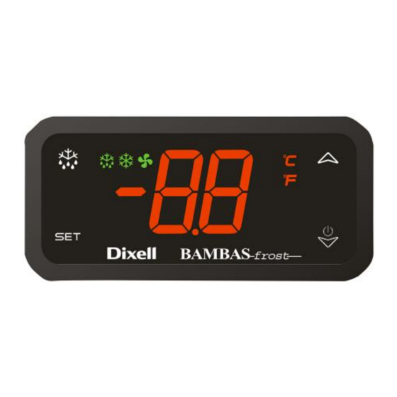
2
GENERAL DESCRIPTION
The XR03CH, in 3274x50mm short format, is microprocessor based controller suitable for applications on
normal temperature refrigerating units. It provides two relay output: one for compressor and the other one for
alarm signalling or as auxiliary output. It provides an NTC probe input and a digital input for alarm signalling,
for switching the auxiliary output or for start defrost. The instrument is fully configurable through special
parameters that can be easily programmed through the keyboard or the by HOTKEY.
3
REGULATION
The regulation is performed according to
the
temperature
measured
by
the
thermostat
probe
with
a
positive
differential from the set point: if the
temperature increases and reaches set
point plus differential the compressor is
started and then turned off when the
temperature reaches the set point value
again.
In case of fault in the thermostat probe the start and stop of the compressor are timed through
parameters Cy and Cn.
4
AUX OUTPUT
The function related to the second relay output can be selected by using par. o1:
-
on = output enabled
-
oFF = output disabled
5
FRONT PANEL COMMANDS
1598040330 XR03CH BMB GB r1.0 27.02.2018
To display target set point, in programming mode it selects a parameter or confirm an
operation
AUX
To activate the auxiliary output
In programming mode it browses the parameter codes or increases the displayed
value
In programming mode it browses the parameter codes or decreases the displayed
value.
Keep it pressed more than 3 sec to power ON and OFF the device.
5.1 KEYS COMBINATION
+
+
+
LED
MODO
On
Compressor enabled
Flashing
Anti-short cycle delay enabled (AC parameter)
On
Heating relay active (if o1=on)
on
Alarm/error
On
Measurement unit
Flashing
Programming mode
On
Measurement unit
Flashing
Programming mode
5.2 HOW TO SEE THE SET POINT
1.
Push and immediately release the SET key, the set point will be showed;
2.
Push and immediately release the SET key or wait about 5s to return to normal visualisation.
5.3 HOW TO CHANGE THE SETPOINT
1.
Push the SET key for more than 2 sec to change the Set point value;
2.
The value of the set point will be displayed and the "°C" or "°F" LED starts blinking;
3.
To change the Set value push the
4.
To memorise the new set point value push the SET key again or wait for 10 sec.
5.4 HOW TO CHANGE A PARAMETER VALUE
To change any parameter's value, operate as follows:
1. Enter the Programming mode by pressing the SET+
blinking).
2. Select the required parameter. Press the "SET" key to display its value
3. Use
or
to change its value.
4. Press "SET" to store the new value and move to the following parameter.
To exit: Press SET+
or wait for 15 sec without pressing a key.
NOTE: the set value is stored even when the procedure is exited by waiting the time-out to expire.
5.5 HIDDEN MENU
The hidden menu includes all the parameters of the instrument.
HOW TO ENTER THE HIDDEN MENU
1. Enter the Programming mode by pressing the SET+
blinking).
2. Released the keys, then push again the SET+
displayed immediately followed from the Hy parameter.
NOW THE HIDDEN MENU IS ACTIVE
3. Select the required parameter.
4. Press the "SET" key to display its value
5. Use
or
to change its value.
6. Press "SET" to store the new value and move to the following parameter.
To exit: Press SET+
or wait 15 sec without pressing a key.
NOTE1: if none parameter is present in L1, after 3 sec the "nP" message will be displayed. Keep the
keys pressed till the L2 message is displayed.
NOTE2: the set value is stored even when the procedure is exited by waiting the time-out to expire.
MOVE A PARAMETER FROM THE HIDDEN MENU TO THE FIRST LEVEL AND
VICEVERSA
Each parameter present in the HIDDEN MENU can be removed or put into "THE FIRST LEVEL"
(user level) by pressing SET+ . In HIDDEN MENU when a parameter is present in First Level the
decimal point is on.
5.6 TO LOCK THE KEYBOARD
Keep pressed for more than 3 sec both
The "OF" message will be displayed and the keyboard will be locked. If a key is pressed more than 3
sec the "OF" message will be displayed.
XR03CH
To lock or unlock the keyboard
To enter in programming mode
To return to room temperature display
SIGNIFICATO
or
arrows within 10 sec.
keys for 3 sec ("°C" or "°F" LED starts
keys for 3 sec ("°C" or "°F" LED starts
keys for more than 7 sec. The L2 label will be
and
buttons.
1/3

Related Manuals for Emerson Dixell XR03CH


Summary of Contents for Emerson Dixell XR03CH
- Page 1 DIGITAL CONTROLLER To display target set point, in programming mode it selects a parameter or confirm an operation XR03CH To activate the auxiliary output GENERAL WARNING __________________________________________________________________ 1 GENERAL DESCRIPTION _______________________________________________________________ 1 In programming mode it browses the parameter codes or increases the displayed REGULATION _________________________________________________________________________ 1 value AUX OUTPUT _________________________________________________________________________ 1...
- Page 2 INSTALLATION AND MOUNTING 5.7 TO UNLOCK THE KEYBOARD Keep pressed together for more than 3 sec both keys till the “on” message will be displayed. The XR03CH shall be mounted on vertical panel, in a 29x71 mm hole, and fixed using the special bracket supplied. PARAMETERS The temperature range allowed for correct operation is from 0 to 60°C.
- Page 3 13 CONNECTIONS NOTE: In model with 110Vac the power supply has to be connected to 6-7 terminals 14 DEFAULT SETTING VALUES LABEL DESCRIPTION RANGE DEFAULT 0.1 to 25°C Differential 2.0°C 1 to 45°F -55°C to SET Minimum Set Point -55°C -67°F to SET SET to 99°C Maximum Set Point...