
Related Manuals for GE BK MEDICAL 8838 Series


Summary of Contents for GE BK MEDICAL 8838 Series
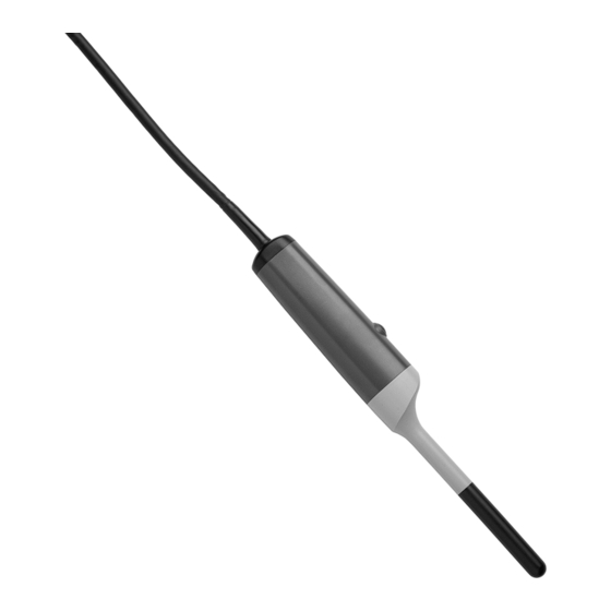
- Page 1 User Guide Type 8838 3DART Transducer English BB1857-H April-2023 For Professional Users Only...
- Page 2 BK MEDICAL Mileparken 34 2730 Herlev Denmark Tel.:+45 4452 8100/Fax:+45 4452 8199 www.bkmedical.com Email: [email protected] The serial number of a BK Medical product contains information about the year of manufacture. To obtain the date of manufacture of a product, please contact your BK Medical representative or write to us at the email address above, including the product’s serial number (SN number).
-
Page 3: Table Of Contents
Contents Introduction ............5 Intended use . -
Page 5: Introduction
Introduction This is the user guide for 3DART Transducer Type 8838 and must be used together with Care and Cleaning which contains important safety information. Caution Rx-c1 United States Federal law restricts this device to sale by or on the order of a physician. Physicians only Intended use... -
Page 6: General Information
Figure 3. 3D imaging plane. General Information Product specifications for this transducer can be found in the Product Data sheet that accompanies this user guide. Acoustic output data and data about EMC (electromagnetic compatibility) for this transducer are in Technical Data (BZ2100) that accompanies this user guide. A full explanation of acoustic output data is given in your system user guide. -
Page 7: Caring For The Transducer
Caring for the Transducer The transducer may be damaged during use or processing, so it must be checked before use for cracks or irregularities in the surface. It should also be checked thoroughly once a month following the procedure in Care and Cleaning. Cleaning and Disinfection To ensure the best results when using BK Medical equipment, it is important to maintain a strict cleaning routine. -
Page 8: Changing Frequency
The transducer is connected to the system using both the array Transducer Socket and the mechanical Transducer Socket. Caution BK-c4 The system must not be imaging when you connect the transducer. The image must be frozen or the system must be turned off. Do not unfreeze the image before you have connected the transducer to both sockets. -
Page 9: Using The Transducer Control Button
Make sure that there is enough imaging gel to cover the entire front end of the transducer (the black part of the transducer). This prevents image artifacts caused by air bubbles. Pull the transducer cover over the transducer. Before imaging, apply a small amount of gel to the outside of the transducer cover to create good acoustic contact between the patient and the transducer. -
Page 10: Rotating The 2D Imaging Plane
Rotating the 2D Imaging Plane Typically, you use a 2D imaging to locate the area where you want a 3D image.You Select key can rotate the 2D imaging plane from the system or the remote control. This allows you to locate the area where you want to image without moving the transducer inside the patient. -
Page 11: 3D Imaging
Figure 5. Rotation screen keys on the flex Focus 1202. On the 2202 UltraView system you have to assign rotation keys to the user-definable keys on the the keyboard. For more information on customizing the 2202 UIltraView keyboard, see the ‘Setting Up and Customizing Your System’... - Page 12 360° Images and the Stitch Angle If you set the Extent parameter for a 3D image to 360°, a stitch angle appears on the image. (The stitch angle parameter is only active when Extent is set to 360°.) The stitch angle is a parameter that you set on the screen. The stitch line is the line Stitch angle vs stitch line that is in the 3D image, reflecting the setting of the stitch angle parameter.
-
Page 13: Cleaning After Use
When you start the imaging, the control panel is locked to avoid accidental interruption of the imaging process. A progress bar is displayed at the top of the image as a graphic image and as the number of seconds remaining to show how much time is left to complete the image. -
Page 14: Disposal
Disposal When the transducer is scrapped at the end of its life, national rules for the relevant material in each individual land must be followed. Within the EU, when you discard the transducer, you must send it to appropriate facilities for recovery and recycling. See the applicable system user guide for further details.