Table of Contents
Quick Links
SIMATIC CM 1542-5
SIMATIC NET
S7-1500 - PROFIBUS
SIMATIC CM 1542-5
Operating Instructions
CM 1542-5, firmware V2.0 (6GK7542-5DX00-0XE0)
CM 1542-5, firmware V3.0 (6GK7542-5DX10-0XE0)
01/2023
C79000-G8976-C290-07
Preface
Application and functions
Installation, wiring,
commissioning, operation,
disassembly
Configuration, program
blocks
Diagnostics and upkeep
Technical specifications
Approvals
Dimension drawings
1
2
3
4
5
6
7
Table of Contents

Related Manuals for Siemens S7-1500 PROFIBUS


Summary of Contents for Siemens S7-1500 PROFIBUS
- Page 1 SIMATIC CM 1542-5 Preface Application and functions Installation, wiring, commissioning, operation, SIMATIC NET disassembly Configuration, program S7-1500 - PROFIBUS blocks SIMATIC CM 1542-5 Diagnostics and upkeep Operating Instructions Technical specifications Approvals Dimension drawings CM 1542-5, firmware V2.0 (6GK7542-5DX00-0XE0) CM 1542-5, firmware V3.0 (6GK7542-5DX10-0XE0) 01/2023 C79000-G8976-C290-07...
- Page 2 Note the following: WARNING Siemens products may only be used for the applications described in the catalog and in the relevant technical documentation. If products and components from other manufacturers are used, these must be recommended or approved by Siemens. Proper transport, storage, installation, assembly, commissioning, operation and maintenance are required to ensure that the products operate safely and without any problems.
-
Page 3: Preface
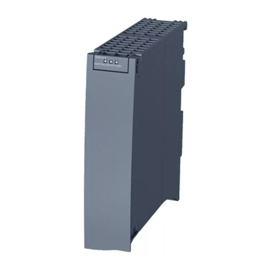
Preface Article number, validity and product names This description contains information on the following product: • CM 1542-5 Article number 6GK7 542-5DX00-0XE0 Hardware version 1 Firmware version V2.0.24 • CM 1542-5 Article number 6GK7 542-5DX10-0XE0 Hardware version 1 Firmware version V3.0 Communications modules for connecting S7-1500 to PROFIBUS DP View of the module ①... - Page 4 You will find the manual on the DVD supplied with the product. This DVD contains the product manuals valid at the time it is created. Current manual edition on the Internet You will also find the current version of this manual on the Internet pages of Siemens Industry Online Support: Link: (https://support.industry.siemens.com/cs/ww/en/ps/15671/man)
- Page 5 • OSS_CM15425_86.pdf • OSS_CM15425_99.pdf Firmware The firmware is signed and encrypted. This ensures that only firmware created by Siemens can be downloaded to the device. Note on firmware/software support Check regularly for new firmware/software versions or security updates and apply them. After the release of a new version, previous versions are no longer supported and are not maintained.
- Page 6 CM 1542-5. The documents are available on the Internet. Table 1 Documentation for the CM 1542-5 Topic Documentation Important contents System S7-1500 automation system • Application planning description (https://support.industry.siemens.com/cs/ww/e • Installation n/view/59191792) system manual • Connecting • Commissioning Module properties Power supplies • Connecting (https://support.industry.siemens.com/cs/ww/e...
- Page 7 Do not dispose of the product at public disposal sites. For environmentally friendly recycling and the disposal of your old device contact a certified disposal company for electronic scrap or your Siemens contact. Keep to the local regulations. SIMATIC CM 1542-5...
- Page 8 Preface You will find information on returning the product on the Internet pages of Siemens Industry Online Support: Link: (https://support.industry.siemens.com/cs/ww/en/view/109479891) SIMATIC NET glossary The SIMATIC NET glossary describes terms that may be used in this document. You will find the SIMATIC NET glossary in the Siemens Industry Online Support at the following address: Link: (https://support.industry.siemens.com/cs/ww/en/view/50305045)
-
Page 9: Table Of Contents
Table of contents Preface ..............................3 Application and functions........................11 Application ........................11 Further functions ....................... 12 Configuration limits and performance data................. 13 1.3.1 Configuration limits - number of CMs ................. 13 1.3.2 Transmission speeds supported ..................14 1.3.3 Characteristic data of the DP interface ................14 1.3.4 Characteristic data of FDL communication ................ - Page 10 Table of contents 4.1.1 Diagnostics options......................43 4.1.2 DP slave diagnostics ......................44 4.1.3 Standard diagnostics ......................45 4.1.4 Device-specific diagnostics in DP-V1 ................... 47 4.1.5 DP diagnostics frames when the CPU is in STOP ..............50 Maintenance ........................50 4.2.1 Update firmware........................
-
Page 11: Application And Functions
– DP master according to EN 50170, DP-V1 – DP master mode for DP slaves according to PROFIBUS DP-V0 and DP-V1 – DP master mode for Siemens DP slaves – Direct data exchange (DP slave to DP slave) As a DP master, the CM 1542-5 is capable of enabling direct data exchange for its assigned DP slaves. -
Page 12: Further Functions
Application and functions 1.2 Further functions • S7 communication – PG communication for uploading / downloading of S7 configuration, diagnostics and routing – Operator control and monitoring functions (HMI communication) – Data exchange over S7 connections • Data record routing / field device parameter assignment You can use the CM as a router for data records intended for field devices (DP slaves). -
Page 13: Configuration Limits And Performance Data
Application and functions 1.3 Configuration limits and performance data Time-of-day synchronization - time master or time slave The CM 1542-5 can be enabled for time-of-day synchronization. As an alternative, the CM can be configured as time master or time slave on PROFIBUS. •... -
Page 14: Transmission Speeds Supported
Remember the cable length For the selected transmission speed, the permitted cable length must be kept to. For this refer to the information in the PROFIBUS function manual: Link: (https://support.industry.siemens.com/cs/ww/en/view/59193579) 1.3.3 Characteristic data of the DP interface Characteristic data of DP mode No special program blocks are required for DP mode. -
Page 15: Characteristic Data Of Fdl Communication
For this reason, lower values than specified here can result. You will find detailed information on the topic of connection resources in the "Communication" function manual: Link: (http://support.automation.siemens.com/WW/view/en/59192925) 1.3.5 Characteristics of S7 communication Characteristics of S7 communication... -
Page 16: Performance Data / Operation
Performance data / operation Measured values of transfer or reaction times Measured values of transfer and reaction times in Ethernet, PROFIBUS and PROFINET networks for a series of configurations can be found on the Internet: Link: (https://support.industry.siemens.com/cs/ww/en/view/25209605) Requirements for use 1.4.1 Usable CPUs The following CPUs can be used as local CPU of the communications module: •... -
Page 17: Project Engineering
CPUs up to date. Check regularly for security updates for the firmware and use them. Information regarding product news and new firmware versions of the communications module is available at the following address: Link: (https://support.industry.siemens.com/cs/ww/en/ps/15671/dl) 1.4.2 Project engineering Configuration To configure the CM, the following configuration tool is required:... -
Page 18: Leds
You can find additional information on "Interrupts" in the STEP 7 online help. You can find additional information on "Diagnostics" and "System alarms" in the function manual on the Internet: Link: (https://support.industry.siemens.com/cs/ww/en/view/59192926) LED display The following figure shows the LEDs of the CM 1542-5. -
Page 19: Profibus Interface
Application and functions 1.6 PROFIBUS interface Meaning of the LED displays The CM 1542-5 has 3 LEDs to display the current operating status and the diagnostics status and these have the following meanings: (one-color LED: green) • RUN/STOP LED (one-color LED: red) •... - Page 20 Application and functions 1.6 PROFIBUS interface SIMATIC CM 1542-5 Operating Instructions, 01/2023, C79000-G8976-C290-07...
-
Page 21: Installation, Wiring, Commissioning, Operation, Disassembly
Installation, wiring, commissioning, operation, disassembly Important notes on using the device Safety notices on the use of the device Note the following safety notices when setting up and operating the device and during all associated work such as installation, connecting up or replacing the device. 2.1.1 Notes on use in hazardous areas WARNING... -
Page 22: Notes On Use In Hazardous Areas According To Atex / Ukex / Iecex / Ccc-Ex
Installation, wiring, commissioning, operation, disassembly 2.1 Important notes on using the device 2.1.2 Notes on use in hazardous areas according to ATEX / UKEX / IECEx / CCC-Ex WARNING Requirements for the cabinet To comply with EU Directive 2014/34 EU (ATEX 114), UK Regulation SI 2016/1107 or the conditions of IECEx or CCC-Ex, the housing or cabinet must meet the requirements of at least IP54 (according to EN/IEC 60529, GB/T 4208) in compliance with EN IEC/IEC 60079-7, GB 3836.8. -
Page 23: Installation, Removal And Repairs In Hazardous Areas
Installation, wiring, commissioning, operation, disassembly 2.2 Installation, removal and repairs in hazardous areas WARNING EXPLOSION HAZARD Replacing components may impair suitability for Class 1, Division 2 or Zone 2. WARNING If the device is installed in a cabinet, the inner temperature of the cabinet corresponds to the ambient temperature of the device. - Page 24 • Observe the device approvals applicable for your country. WARNING Unauthorized repair of devices in explosion-proof design Risk of explosion in hazardous areas • Repair work may only be performed by personnel authorized by Siemens. SIMATIC CM 1542-5 Operating Instructions, 01/2023, C79000-G8976-C290-07...
-
Page 25: Installing, Connecting And Commissioning
Installation, wiring, commissioning, operation, disassembly 2.3 Installing, connecting and commissioning Installing, connecting and commissioning WARNING Read the system manual "S7-1500 Automation System" Prior to mounting, connection and commissioning, read the relevant sections in the system manual "S7-1500 Automation System", see Preface (Page 3) > Documentation guide. Make sure that the power supply is turned off when installing/uninstalling the devices. -
Page 26: Mode Of The Cpu - Effect On The Cm
Installation, wiring, commissioning, operation, disassembly 2.4 Mode of the CPU - effect on the CM Procedure for connection and mounting Step Execution Notes and explanations Install the CM as described in the system manual "S7 1500 Automation System", section "Installing I/O devices". -
Page 27: Disassembly
Installation, wiring, commissioning, operation, disassembly 2.5 Disassembly Changing the CPU from STOP to RUN • Programmed connections are established. • In DP master mode: – Change from CLEAR to the OPERATE mode • In DP slave mode: – Going diagnostics interrupt to the master –... - Page 28 Installation, wiring, commissioning, operation, disassembly 2.5 Disassembly SIMATIC CM 1542-5 Operating Instructions, 01/2023, C79000-G8976-C290-07...
-
Page 29: Configuration, Program Blocks
Configuring in third-party systems via GSD file To allow configuration as DP slave in third-party systems, a GSD file is available. You will find this on the following page of Siemens Industry Online Support: Link: (https://support.industry.siemens.com/cs/ww/en/view/113652) The protocol variant DP-V1 or DP-V0 is decided during operation by the setting of the connected DP master. -
Page 30: Configuration Of The Extended Lsap Area
Configuration, program blocks 3.4 Configuration of the extended LSAP area Writing address with WRREC To write the PROFIBUS address, use the instruction WRREC. You enter the PROFIBUS address in the "RECORD" parameter (data record number 2101) of the block according to the following structure: record Struct UInt... - Page 31 Configuration, program blocks 3.4 Configuration of the extended LSAP area Requirements for the LSAP reservation • CM 1542-5 with firmware version V2.0.20 or higher • STEP 7 Professional V15.1 Update 2 Preparation of existing projects If you want to use the function in an existing STEP 7 project up to V15.1, do the following: 1.
- Page 32 Configuration, program blocks 3.4 Configuration of the extended LSAP area 4. In the global data block, create a variable of the data type "TCON_FDL". To do this, enter "TCON_FDL" in the data type field. The connection description for an FDL connection is created automatically. Figure 3-1 Parameters of the TCON_FDL variable in the connection description DB The connection type ("ConnectionType"...
- Page 33 Configuration, program blocks 3.4 Configuration of the extended LSAP area TRCV – Use the same connection ID as previously configured in "TCON". Please note: The payload received with this block does not contain the "RemotePBAddress" and "RemoteLSAP" parameters. Therefore, these parameters cannot be evaluated. TURCV –...
- Page 34 Configuration, program blocks 3.4 Configuration of the extended LSAP area 4. In the global data block, create a variable of the data type "TCON_FDL". To do this, enter "TCON_FDL" in the data type field. The connection description for an FDL connection is created automatically. The connection type ("ConnectionType"...
-
Page 35: Program Blocks For Communication And Distributed I/O
Configuration, program blocks 3.5 Program blocks for communication and distributed I/O Note: The "TSEND_C" block can also be used for connection establishment and sending. Configuration in the "Network data" editor Proceed as follows to assign the reserved LSAPs to a connection: 1. -
Page 36: Program Blocks For Fdl
Configuration, program blocks 3.6 Program blocks for FDL System blocks and Meaning when used with CM system functions SETIO Transferring the process image of a DP standard slave GETIO_PART Reading the process image partition of a DP standard slave SETIO_PART Transferring the process image partition of a DP standard slave D_ACT_DP Disable / enable DP slaves... - Page 37 Configuration, program blocks 3.6 Program blocks for FDL Supported program blocks for OUC The following instructions in the specified minimum version are available for programming Open User Communication to use FDL: • TSEND_C V3.1 / TRCV_C V3.1 Compact blocks for connection establishment and for sending and receiving data via a configured or programmed connection As an alternative: •...
- Page 38 Configuration, program blocks 3.6 Program blocks for FDL Note Connection abort If an existing connection is aborted by the communications partner or due to disturbances on the network, the connection must also be terminated by calling TDISCON. Make sure that you take this into account in your programming.
- Page 39 Configuration, program blocks 3.6 Program blocks for FDL Setting up a configured FDL connection using TSEND_C Proceed as follows to set up a configured FDL connection in STEP 7: 1. Create a TSEND_C instruction in the program editor. You will be prompted to create the relevant data block. 2.
- Page 40 Configuration, program blocks 3.6 Program blocks for FDL Setting up a programmed FDL connection using TSEND_C To set up a programmed FDL connection in STEP 7, follow the steps below: 1. Create a TSEND_C instruction in the program editor. You will be prompted to create the relevant data block. 2.
- Page 41 Configuration, program blocks 3.6 Program blocks for FDL Figure 3-4 Example: TCON instruction for FDL connection The parameters of TCON_FDL You will find information on the parameters of TCON_FDL in the STEP 7 information system. Note the special features of the parameters "RemoteSAP" and "RemotePBAddress": •...
- Page 42 Configuration, program blocks 3.6 Program blocks for FDL SIMATIC CM 1542-5 Operating Instructions, 01/2023, C79000-G8976-C290-07...
-
Page 43: Diagnostics And Upkeep
Diagnostics and upkeep Diagnostics 4.1.1 Diagnostics options Diagnostics options You have the following diagnostics options available for the module: • The LEDs of the module Diagnostics using the LEDs is the first means of narrowing down errors/faults. To narrow the error/fault down even further, evaluate the message on the display of the S7-1500 CPU. -
Page 44: Dp Slave Diagnostics
Diagnostics and upkeep 4.1 Diagnostics 4.1.2 DP slave diagnostics DP-V1 slave: Diagnostics interrupt The diagnostics data is transferred as a diagnostics interrupt. Diagnostics interrupts must be acknowledged by the DP master. Supported diagnostics functions The CM 1542-5 supports the following blocks of DP diagnostics: •... -
Page 45: Standard Diagnostics
Diagnostics and upkeep 4.1 Diagnostics DP-V1 slave Table 4- 1 Overview of device-specific diagnostics of the CM with DP-V1 slaves Device-specific diagnostics Byte Meaning Header Variant Variant Interrupt type Status type Slot number Variant Variant Interrupt specifier Status specifier 4...62 Module-specific diagnostics data 4.1.3 Standard diagnostics... - Page 46 Diagnostics and upkeep 4.1 Diagnostics Bit no. Name Explanation Station_Not_Ready The DP slave is not ready for productive data exchange. This is a temporary status that cannot be influenced by the DP master. Station_Non_Existent The DP slave is not reacting on the bus. This bit is set by the DP master 1 (the slave sets this bit permanently to 0).
-
Page 47: Device-Specific Diagnostics In Dp-V1
Diagnostics and upkeep 4.1 Diagnostics Bytes 4 and 5: Vendor ID of the slave ("Ident_Number") The vendor ID ("Ident_Number") for the DP slave type is entered in bytes 4 and 5. This identifier can be used to identify the slave. The more significant part of the value is in byte 5. - Page 48 Diagnostics and upkeep 4.1 Diagnostics Byte 1: Variant "Status type" Table 4- 6 Structure of byte 1 of the device-specific diagnostics (variant "status type") Bit no. Meaning Value Meaning Status information Status_Type 6...0 - reserved - Status information Modul_Status (see also bytes 4...62) 3...31 - reserved - 32...126...
- Page 49 Diagnostics and upkeep 4.1 Diagnostics Byte 3: Variant "Status specifier" Table 4- 8 Structure of byte 3 of the device-specific diagnostics (variant "status specifier") Bit no. Meaning 7...2 - reserved - 1...0 Status_Specifier No further distinction Status appears Status disappears - reserved - Bytes 4...62: Module-specific diagnostics: General coding This byte contains data with module-specific information that is described in the relevant...
-
Page 50: Dp Diagnostics Frames When The Cpu Is In Stop
Do not use any liquids or solvents. WARNING Unauthorized repair of devices in explosion-proof design Risk of explosion in hazardous areas • Repair work may only be performed by personnel authorized by Siemens. SIMATIC CM 1542-5 Operating Instructions, 01/2023, C79000-G8976-C290-07... -
Page 51: Update Firmware
New firmware versions of the module If a new firmware version is available for the communications module, you will find this on the Internet pages of Siemens Industry Online Support: Link: (https://support.industry.siemens.com/cs/ww/en/ps/15671/dl) Firmware files have the file format *.upd. Save the file on your PC. - Page 52 Diagnostics and upkeep 4.2 Maintenance Loading the firmware with the online functions of STEP 7 via Ethernet Note Duration of the firmware update Downloading a new firmware file can take several minutes. Always wait until the completion of the firmware update can be recognized from the LEDs (see below).
-
Page 53: Module Replacement
Diagnostics and upkeep 4.2 Maintenance Requirements: • You have copied the new firmware file from your PC to the SD card using a suitable card reader. • Optional: You have saved a backup file of the currently used firmware file. Procedure: 1. - Page 54 Diagnostics and upkeep 4.2 Maintenance SIMATIC CM 1542-5 Operating Instructions, 01/2023, C79000-G8976-C290-07...
-
Page 55: Technical Specifications
Technical specifications Technical specifications of the CM (6GK7542-5DX00-0XE0) You will find the product functions in the section Configuration limits and performance data (Page 13). In the preface, "Guide to documentation" section, note the information in the SIMATIC S7- 1500 System Manual (Page 3). In addition to the information in the system description, the following technical specifications apply to the module. -
Page 56: Technical Specifications Of The Cm (6Gk7542-5Dx10-0Xe0)
Technical specifications 5.2 Technical specifications of the CM (6GK7542-5DX10-0XE0) Technical specifications of the CM (6GK7542-5DX10-0XE0) You will find the product functions in the section Configuration limits and performance data (Page 13). In the preface, "Guide to documentation" section, note the information in the SIMATIC S7- 1500 System Manual (Page 3). -
Page 57: Profibus Interface Terminal Assignment
Technical specifications 5.3 PROFIBUS interface terminal assignment PROFIBUS interface terminal assignment PROFIBUS interface The table below shows the terminal assignment of the PROFIBUS interface. The assignment corresponds to the standard assignment of RS485 interface. Table 5- 1 Terminal assignment PROFIBUS interface View Signal name Designation... - Page 58 Technical specifications 5.4 Ambient temperature The following derating factors and maximum ambient temperatures apply. Table 5- 2 Restrictions of the maximum permissible ambient temperature in relation to the installation altitude Installation altitude Derating factor Maximum ambient temperature when the rack is mounted horizontally (Height above mean sea level)
-
Page 59: Approvals
The approvals for shipbuilding are an exception to this. Certificates for shipbuilding and national approvals The device certificates for shipbuilding and special national approvals can be found in Siemens Industry Online Support on the Internet: Link: (https://support.industry.siemens.com/cs/ww/en/ps/15671/cert) Documents on the Internet... - Page 60 Directive of the European Parliament and of the Council of 8 June 2011 on the restriction of the use of certain hazardous substances in electrical and electronic equipment UK Declaration of Conformity Importer UK: Siemens plc Sir William Siemens House Princess Road Manchester M20 2UR The product meets the requirements of the following directives: •...
- Page 61 • EN IEC 60079-0 - Explosive atmospheres - Part 0: Equipment - General requirements • EN 60079-7 - Explosive Atmospheres - Part 7: Equipment protection by increased safety 'e' Importer UK: Siemens plc (see above) CCC-Ex classification:Ex na IIC T4 Gc The product meets the requirements of the following standards: •...
- Page 62 Approvals Applied standards: • EN 61000-6-2 Electromagnetic compatibility (EMC) - Part 6-2: Generic standards - Immunity for industrial environments • EN 61000-6-4 Electromagnetic compatibility (EMC) - Part 6-4: Generic standards - Emission standard for industrial environments RoHS The device meets the requirements of the following guidelines: •...
- Page 63 Approvals Note For devices with C-PLUG memory: The C-PLUG memory module may only be inserted or removed when the power is off. CSA Certification Mark Canadian Standard Association (CSA) nach Standard C 22.2 No. 142: • Certification Record 063533–C-000 Factory Mutual Approval Standards: •...
- Page 64 SIMATIC NET products are regularly submitted to the relevant authorities and approval centers for approvals relating to specific markets and applications. If you require a list of the current approvals for individual devices, consult your Siemens contact or check the Internet pages of Siemens Industry Online Support: Link: (https://support.industry.siemens.com/cs/ww/en/ps/15671/cert)
-
Page 65: Dimension Drawings
Dimension drawings All dimensions in the dimension drawings are in millimeters. Figure 7-1 Front view SIMATIC CM 1542-5 Operating Instructions, 01/2023, C79000-G8976-C290-07... - Page 66 Dimension drawings Figure 7-2 Side view SIMATIC CM 1542-5 Operating Instructions, 01/2023, C79000-G8976-C290-07...
-
Page 67: Index
Index Firmware CM (for FDL), 18 CPU, 18 Updating, 51 Bus topology, 12 Glossary, 8 Cable length, 14 Characteristic data (DP), 14 Characteristic data (FDL), 15 Characteristics (S7 communication), 15 Configuration data HMI functions, 15 Downloading, 17 Connection resources of the CPU, 15 Instruction DE_ACT, 12 Data record routing, 11, 15... - Page 68 Index S7 communication, 11 S7 connections, 11, 15 S7 routing function, 27 Safety notices, 21 Siemens DP slave, 11 SIMATIC NET glossary, 8 Startup parameters DP, 14 STEP 7 (version), 17 SYNC/FREEZE, 11 TCON_FDL, 36, 40 Time master, 13 Time slave, 13...