ABB SafeRing Product Manual
Hide thumbs
Also See for SafeRing:
- Installation, service and maintenance instructions (36 pages) ,
- Installation and operating instructions manual (24 pages) ,
- Installation instructions manual (15 pages)

Related Manuals for ABB SafeRing


Summary of Contents for ABB SafeRing
- Page 1 Product manual SafeRing / SafePlus 12-24kV Installation and operating instructions...
-
Page 2: Table Of Contents
Crucial information General description Outer assembly Transport and handling By receiving inspection Storage Technical data Electrical data SafeRing Electrical data SafePlus Installation Standard 3-way switchgear 3-way switchgear with base frame (AFL) 3-way switchgear with base frame (AFLR) Dimensions Internal arc classification (IAC) - Page 3 Service and maintenance 20.1 General warnings and cautions 20.2 Maintenance intervals 20.3 Inspection 20.4 Servicing 20.5 Repairs 20.6 Tool list SafeRing/SafePlus Environmental certification 21.1 Life expectancy of product 21.2 Recycling capability 21.3 End-of-life...
-
Page 4: Safety
IEC safety regulations and those of other technical authorities, and also respecting other overriding instructions. It is recommended that ABB service personnel be called in to perform the servic- ing and repair work. 1.3 CRUCIAL INFORMATION... -
Page 5: General Description
The units are delivered from the factory ready for installation. SafeRing can be supplied as a 2, 3 or 4-way unit in standard configurations with additional equipment according to custo- mer specification. -
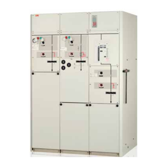
Page 6: Outer Assembly
2.1 OUTER ASSEMBLY Upper front cover 1. Manometer 2. Nameplate of module SafePlus 3. Short circuit indicator 4. Capacitive voltage indication 5. Load break / earthing switch position indicator 6. Push buttons close/open operation 7. Charged spring indicator 8. Self-powered protection relay 9. -
Page 7: Transport And Handling
350 kg The weights are without additional equipment, except for transformers for M- and Mt-modules SafeRing / SafePlus is fitted with lifting lugs, but can also be moved on a pallet with a forklift truck. Make sure to secure the switchgear. -
Page 8: Technical Data
4. TECHNICAL DATA 4.1 ELECTRICAL DATA SAFERING C-module F-module V-module SafeRing Switch Switch-fuse Vacuum Earthing switch Earthing switch Earthing switch disconnector combination circuit-breaker Rated voltage 12/17,5/24 12/17,5/24 12/17,5/24 12/17,5/24 12/17,5/24 12/17,5/24 Power frequency withstand voltage kV /38/50 /38/50 /38/50 /38/50... -
Page 9: Installation
5. INSTALLATION NOTE NOTE The floor must be well leveled and the unit must be The tools required for installation and maintenance fixed by means of anchor bolts in accordance with of the switchgear are specified in the tool list in the dimensional drawing for the number of modules chapter 20.6. -
Page 10: 3-Way Switchgear With Base Frame (Afl)
5.2 3-WAY SWITCHGEAR WITH BASE FRAME (AFL) Unit 1-way 2-way 3-way 1021 4-way 1272 1312 1346 5-way 1597 1637 1671... -
Page 11: 3-Way Switchgear With Base Frame (Aflr)
5.3 3-WAY SWITCHGEAR WITH BASE FRAME (AFLR) indicates cable entry Unit 1-way 2-way 3-way 1021 4-way 1273 1312 1346 5-way 1598 1637 1671 81/87* Distance between two units which are connec- ted to each other by means of external busbars *) Top extension: 8 mm / 81 mm Side extension: 14 mm / 87 mm 8/14*... - Page 12 Base frame, height 450 mm Base frame, height 290 mm AFLR baseframe * Dimensions for 290 mm baseframe Standard switchgear installed on cable Low version switchgear installed on cable trench trench...
-
Page 13: Dimensions
6. DIMENSIONS Height (mm) Standard switchgear Lower version switchgear Standard 1336 1626 1786 2002 2002 1100 1390 1550 without low Top connection without dead ends 1466 1756 1916 2002 2002 1230 1520 1680 voltage Top connection with dead ends 1561 1851 2011 2002... -
Page 14: Internal Arc Classification (Iac)
7. INTERNAL ARC CLASSIFICATION (IAC) During development of all ABB products, focus is put on personnel safety. This is why the SafeRing/SafePlus portfolio was designed and tested for a variety of internal arc scenarios in order to withstand an internal arc of the same current level as a maximum short circuit current. - Page 15 When installing Ring Main Unit or Compact Switchgear with Internal Arc Classification AFL with ventilation be- hind the switchgear, the following must be considered: − Unit must be equipped with arc proof cable covers. − Distance from floor to roof must be minimum 2400 mm −...
- Page 16 For installation of switchgear with Internal Arc Classifi- cation AFLR with ventilation upwards through exhaust channel, the following must be considered: − Unit must be equipped with arc proof cable covers − Unit can be installed as free standing − Minimum height of ceiling: 2600 mm −...
-
Page 17: Cable Compartment
8. CABLE COMPARTMENT CAUTION NOTE In case of interlocked cable compartment, cover The tools required for installation and maintenance can be opened / closed only when earthing switch of the switchgear are specified in the tool list in is in closed position. chapter 20.6. -
Page 18: Cable Connection
All bushings are situated in the same height from the floor and are protected by the cable cover. SafeRing / SafePlus can be supplied with the following bus- hings for the various type of cubicles: Type of module... -
Page 19: Extension Of Switchgear
SafePlus SafePlus SafePlus 1VDD006006 GB. 9.2 SIDE EXTENSION SafeRing and SafePlus can be equipped with a side extensi- on. See separate instruction manual 1VDD006106GB. 10. CURRENT AND VOLTAGE TRANSFORMERS SafeRing and SafePlus can be equipped with current and/or voltage transformers. -
Page 20: Motor Operation
We reserve all rights in this document and in the information contained therein: Reproduction, use or disclosure to third parties without express authority is strictly forbidden. © ABB Technology Ltd. without express authority is strictly forbidden. © ABB Technology Ltd. -
Page 21: Relay And Current Transformers
SafeRing / SafePlus with vacuum circuit-breakers are delivered with self-powered OC / EF protection relay ABB type REJ 603 V.1,5. Relays with auxiliary voltage SafePlus can be delivered with advanced protection relays: −... -
Page 22: Pressure Indicator
SafeRing / SafePlus contain SF -gas with a nominal pressure of 1,4 bar absolute at 20 SafeRing / SafePlus are «sealed for life» and fitted with a temperature-compensated pressure indicator. Pointer in green area - unit has sufficient pressure. Pointer in red area - pressure is too low. -
Page 23: Altitude
1500 meters. In the interval from 1500 to pressure in higher altitudes 2500 meters, gas pressure has to be reduced according to the above figure. For installation above 2500 meters, please contact ABB for instructions. 13.2.1 ADJUSTMENT OF GAS PRESSURE IN HIGHER ALTITUDES Remove the front cover in order to get access to the top of the manometer. -
Page 24: Operation Of The Switchgear
One of the physical properties of vacuum insulation is the Normal ambient conditions possibility of X-ray emissions when the contact gap is open. SafeRing / SafePlus is generally equipped for operation/ The specified test performed by the Physikalisch-Technische service in normal indoor conditions in accordance with Bundesanstalt (PTB) in Braunschweig demonstrates that the IEC 62271-1. -
Page 25: General Warnings And Precautions
Operations and any type of work must be carried − Pressure resistance in the case of an arc fault out by trained and specialized personnel who are − Ventilation familiar with SafeRing/SafePlus and follow all the − Temperature safety regulations in accordance with the IEC Stan- − Humidity dards and other regulations in force, as well as any local work regulations and instructions. -
Page 26: Operation Of Cable Switch
15. OPERATION 15.1 OPERATION OF CABLE SWITCH All switches can be operated with the included operating handle. Internal mechanical interlocking between the switch discon- nector/isolator and the associated earthing switches pre- vents incorrect operation. For detailed interlocking descrip- tion, see dedicated overview for each module in catalogue 1VDD006104 GB. -
Page 27: Operation Of Vacuum Circuit-Breaker
15.2 OPERATION OF VACUUM CIRCUIT-BREAKER The isolator in the V-module can only be opened after the circuit-breaker is opened. Then the circuit-breaker can be closed for testing purposes. Mechanical position indicators: Switch disconnector: Green push-button closes the switch Close: Turn the operating handle clockwise. Red push-button opens the switch Open: Turn the operating handle anti-clockwise. -
Page 28: Operation Of Vacuum Circuit-Breaker 12Kv/25Ka, 24Kv/20Ka
15.3 OPERATION OF VACUUM CIRCUIT-BREAKER - 12kV/25kA, 24kV/20kA Push button - vacuum circuit-breaker (OFF) Push button - vacuum circuit-breaker (ON) Indication - spring charged / discharged Vacuum circuit-breaker position indicator Counter - closing and opening operations Spring-charging lever Before operating of the vacuum circuit-breaker, check that the spring is charged. -
Page 29: Operation Of Fuse-Switch Disconnector
15.4 OPERATION OF FUSE-SWITCH DISCONNECTOR 15.5 INSTALLATION AND REPLACEMENT OF FUSE-LINKS A red indicator below the fuse symbol on the lower front panel WARNING indicates that at least one fuse-link has blown. Fuse links are For correct function of F-module, it is required replaced as shown in the sequence of illustrations. - Page 30 3. Unscrew the fuse panel. 7. Fix the fuses to the fuse cover using the contact screw. 4. Tilt out the fuse panel to gain access to fuse canisters This point is not applicable if fuse fastening is spring - If safety wires are installed, make sure they are latched at based.
-
Page 31: Fuse Selection Tables
7,2 kV 12 kV 13,8 17,5 kV 17,5 24 kV - The table is based on using fuses type ABB CEF - Normal operating conditions with no overload - Ambient temperature -25 C - +40 Fuse-link 120% Transformer rating (kVA) -
Page 32: Fuse Selection Table - Cef-S
– Magnetizing inrush current for transformers above 630kVA - 10 x In during 100ms – Standard ambient working conditions for SafeRing / SafePlus switchgear (most important: ambient temperature -25 ºC to +40 ºC),... -
Page 33: Metering Module
16. METERING MODULE DANGER! Make sure there is no voltage in the busbars and cable terminals and that the risk of reconnection is eliminated in all units. Any remote control must also be prevented. Turn 90 to open 2. Use handles to lift door first up (vertical), then pull the door out (horizontal). -
Page 34: Capacitive Voltage Indicators
17. CAPACITIVE VOLTAGE INDICATORS Each module of switchgears is equipped with a capacitive voltage indicator in accordance with either IEC 61958 (VPIS) or IEC 61243-5 (VDS). 17.1 VOLTAGE INDICATORS VPIS VPIS indicators are used to indicate the presence of service medium voltage. -
Page 35: Voltage Indicators Vds
17.2 VOLTAGE INDICATORS VDS VDS is used to detect the presence or absence of medium voltage according to IEC 61243-5. The VDS are based on the HR system. The system consists of a fixed device, installed in the switchgear, coupled with a mobile device to visually detect the presence or absence of service voltage and phase balance and on which the indicator lights are installed. -
Page 36: Additional Equipment
A shunt trip coil (AC or DC) can be fitted on the transformer switch/breaker. 18.2 REMOTE CONTROL AND MONITORING UNIT SafeRing can be equipped with an integrated remote control and monitoring unit (see picture left). This unit is pre-engineered and can be delivered and installed as a retrofit solution or complete from factory. -
Page 37: Cable Testing
Remember that the cable has two ends. Both ends of the cable need to be isolated. This is typically done by opening the disconnectors of SafeRing SafePlus switchgears connected to the cable. The free end of the tested cable needs to be secured against accidental access. -
Page 38: Procedure For Testing Directly On The Cable Connector With The Cable Connected To The Switchgear
7. Disconnect test equipment. 19.3 PROCEDURE FOR TESTING DIRECTLY ON THE 19.2 PROCEDURE FOR TESTING DIRECTLY ON THE CABLE CONNECTOR WITH THE CABLE DISCONNECTED CABLE CONNECTOR WITH THE CABLE CONNECTED TO FROM THE SWITCHGEAR THE SWITCHGEAR 1. Open switch disconnector. 1. -
Page 39: Service And Maintenance
Other services may be required, as when max number of ope- 4. Make sure that auxiliary circuits are also dis- rations is reached, please contact ABB to order inspection. connected from all possible power supply sources (including instrument transformers) -
Page 40: Servicing
“ over the surface concerned is often effective as a maintenance work as described in chapter 20. temporary remedy. It is advisable to ask the ABB after-sales service department for advice regarding permanent solutions to this uncommon type of Tools Required problem. - Page 41 Tools Required Extra tools Adjustable wrench 10“ Head lamp - LED Side cutting plier - ergo Flashlight LED Strippling plier Multi-purpose service spray 5-56 Universal plier Permanent Marker Bits set with screwdriver handle Small cable ties L=203 x 2,5mm 3/8“ Long ratchet L = 50 cm Large cable ties L=375 x 7,6mm 3/8“...
-
Page 42: Environmental Certification
We also recommend ABB’s website : http://www.abb.com/sf6 the protection of the environment and adhere to ISO 14001 standards. It is our obligation to facilitate end-of-life recycling ABB AS, Electrification Products division in Skien is equipped for our products. to reclaim SF gas from discarded switchgears. - Page 44 Text and illustrations are not For more information please contact: binding. The right to make alterations ABB AS is reserved Electrification Products division P.O. Box 108, Sentrum ©Copyright 2016 ABB N-3701 Skien, Norway All rights reserved Phone: +47 35 58 20 00 www.abb.com...