Dormakaba ED50 Installation Instructions Manual
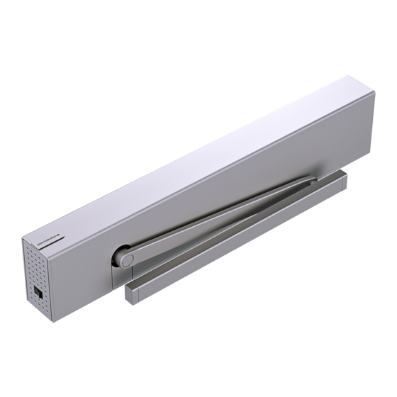
Swing door operators narrow header
Hide thumbs
Also See for ED50:
- Installation instructions manual (116 pages) ,
- Manual (74 pages) ,
- Owner's manual (20 pages)

Related Manuals for Dormakaba ED50


Summary of Contents for Dormakaba ED50
- Page 1 ED50/ED100/ED250 Swing Door Operators Narrow header Installation Instructions DL4616-005– 11-2022 | EN |...
-
Page 2: Table Of Contents
ED50/ED100/ED250 operators – Narrow header Table of Contents Installation Instructions Table of contents Table of contents Installation templates General information Narrow header (4 x 6") – General information push arm template Product overview Narrow header (4 x 6") –... - Page 3 ED50/ED100/ED250 operators – Narrow header Table of Contents Installation Instructions Pull arm installation 10.1 Pull arm installation 10.2 Pull arm assemblies 10.3 Deep pull arm hardware 10.4 Slide shoe assembly 10.5 Install hardware into track 10.6 Standard arm 10.7 Deep pull arm 10.8...
-
Page 4: General Information
ED50/ED100/ED250 operators – Narrow header Chapter 1 Installation Instructions 1 General information 1.1 General information 1.1.1 Installation Instructions. 1.1.5 Symbols used in these instructions. This manual provides installation instructions for the following ED50/ED100/ED250 narrow header surface WARNING applied door configurations. -
Page 5: Product Overview
Installation Instructions 2 Product overview 2.1 Maximum door weights and door installation 2.1.1 Interior building surface installation. Table 2.1.1 ED50 low energy door panel Exterior and interior applications NOTICE Prevailing conditions at opening must be considered Installation on an interior building surface. -
Page 6: Single Door Configuration Examples
ED50/ED100/ED250 operators – Narrow header Chapter 2 Installation Instructions 2.2 Single door configuration examples Fig. 2.2.1 RH pull Fig. 2.2.2 RH pull as a push Fig. 2.2.3 RH push 2.3 Double door configuration examples Fig. 2.3.1 Pull Fig. 2.3.2 Push Fig. -
Page 7: Single Door Narrow Header
ED50/ED100/ED250 operators – Narrow header Chapter 2 Installation Instructions 2.4 Single door narrow header Fig. 2.4.1 Narrow header with cover ED50/ED100/ ED250 surface applied 4" x 6" header ED100/ED250 operator Fig. 2.4.2 Narrow header with cover removed 2.5 Double door narrow header Fig. -
Page 8: Screw Packs
ED50/ED100/ED250 operators – Narrow header Chapter 2 Installation Instructions 2.7 Screw packs Fig. 2.7.1 Mounting plate screws Fig. 2.7.2 Header mounting screw pack DK4608-010 #12 x 2.5 RHWSP 8.2 1/4-20 x 1.5 PHSLFP 1/4-20 x 1" FHMSP (flat head machine screw, Phillips) 2.8 Axle extensions, ED50/ED100/ED250... -
Page 9: Kit, Ed Operator Labels
ED50/ED100/ED250 operators – Narrow header Chapter 2 Installation Instructions 2.10 Kit, ED operator labels Label, Service call Fig. 2.10.1 Kit, ED Operator Label LE, DK3137-0X0 Assembly # Item # Quantity DD3425-010 SAFETY INFORMATION Safety Information Low Energy Swinging Doors... -
Page 10: Mode And Exit Only Switch Panel
ED50/ED100/ED250 operators – Narrow header Chapter 2 Installation Instructions 2.11 Mode and Exit Only switch panel 2.11.1 Mode switch kit. Fig. 2.11.1 Kit, Mode switch Mode Switch Mode switch cable Item Description Kit # length Kit, Mode Switch DX4604-04C... -
Page 11: Push Arm Kits
ED50/ED100/ED250 operators – Narrow header Chapter 2 Installation Instructions 2.14 Push arm kits Fig. 2.14.1 Push arm kit Fig. 2.14.2 Deep push arm kit Standard push DK4709-01X DK4709-02X DC4677-01X Deep push arm, DC4677-02X Screw kit, DK2719-010 2.15 Pull arm kits Fig. -
Page 12: Technical Data
ED50/ED100/ED250 operators – Narrow header Chapter 3 Installation Instructions 3 Technical data 3.1 ED50/ED100/ED250 operator technical data 3.1.1 Operating conditions. 3.1.3 Inputs Wire size Ambient temperature 5 to 122 °F [-15 to 50⁰ C] 14 AWG Connector plug 1/16”... -
Page 13: Ed50 Operating Specifications
ED50/ED100/ED250 operators – Narrow header Chapter 3 Installation Instructions 3.2 ED50 operating specifications 3.2.1 ED50 Maximum opening May be limited by speed, °/s Maximum power door weight after 120 watt Maximum closing consumption learning cycle. speed, °/s Opening force... -
Page 14: Ed100/Ed250 Torque Overview
ED50/ED100/ED250 operators – Narrow header Chapter 3 Installation Instructions 3.4 ED100/ED250 torque overview Mounting on opposite hinge side, Mounting on hinge side, push version of standard arm/ pull version of slide channel. push version of slide channel 3.3.1 ED100... -
Page 15: Ed50/E100/Ed250 Terminal Board
ED50/ED100/ED250 operators – Narrow header Chapter 4 Installation Instructions 4 ED50/E100/ED250 terminal board interfaces 4.1 ED50/ED100/ED250 terminal board interfaces Fig. 4.1.1 Terminal board electrical connections Green LED Activation inputs Night- Yellow LED Interior Exterior Safety sensors bank Red LED... -
Page 16: Recommended Tools And Torque Chart
ED50/ED100/ED250 operators – Narrow header Chapter 5 Installation Instructions 5 Recommended tools and torque chart 5.1 Recommended tools Fig. 5.1.1 Recommended tools T-handle hex key, 5 Hex keys, 2.5 mm, 3 mm, 6 mm Screwdriver, flat blade Door pressure... -
Page 17: Ed50/Ed100/Ed250 Door Signage
ED50/ED100/ED250 operators – Narrow header Chapter 6 Installation Instructions 6 ED50/ED100/ED250 door signage 6.1 ED100/ED250 full energy operator 6.1.1 Overview Fig. 6.1.1 One decal, approach side, non-approach side Signage and warnings are specified in ANSI /BHMA A156.10, American National Standard for Power DO NOT Operated Pedestrian Doors, paragraph 11. -
Page 18: Safety Label, Automatic Swing Doors
The appropriate be in good condition. signage should be present. by an ED50 operator or an ED100/ED250 operator configured for the low energy mode. 7. Have door inspected by an 6. Have door inspected by an AAADM certified inspector... -
Page 19: Door Signage, Full Energy Single Swing Doors
ED50/ED100/ED250 operators – Narrow header Chapter 6 Installation Instructions 6.5 Door signage, full energy single swing doors Fig. 6.5.1 One decal, one way traffic Fig. 6.5.2 One decal, two way traffic Non-swing side Swing side Approach Non-approach DO NOT... -
Page 20: Door Signage, Full Energy Double Swing
ED50/ED100/ED250 operators – Narrow header Chapter 6 Installation Instructions 6.7 Door signage, full energy double swing doors Fig. 6.7.1 One way traffic, approach side Fig. 6.7.2 One way traffic, non-approach side DO NOT DO NOT ENTER ENTER dormakaba dormakaba... - Page 21 ED50/ED100/ED250 operators – Narrow header Chapter 6 Installation Instructions Fig. 6.7.7 Double egress, RH, one way traffic, interior Fig. 6.7.8 Double egress, RH, one way traffic, exterior Approach side Swing side Swing side Approach side DO NOT DO NOT...
-
Page 22: Door Signage, Low Energy Double Swing Doors
ED50/ED100/ED250 operators – Narrow header Chapter 6 Installation Instructions 6.8 Door signage, low energy double swing doors Fig. 6.8.1 Knowing act, SA header side Fig. 6.8.2 Knowing act, hinge side AUTOMATIC AUTOMATIC AUTOMATIC AUTOMATIC CAUTION CAUTION CAUTION CAUTION DOOR... -
Page 23: Installation Templates
ED50/ED100/ED250 operators – Narrow header Chapter 7 Installation Instructions 7 Installation templates 7.1 Narrow header (4 x 6") – push arm template Fig. 7.1.1 Standard push arm template 0 to 8 3/4” Reveal depth 90° 20” [509] Header width = door width + 3”... -
Page 24: Narrow Header (4 X 6") - Deep Push Arm Installation Template
ED50/ED100/ED250 operators – Narrow header Chapter 7 Installation Instructions 7.2 Narrow header (4 x 6") – deep push arm installation template Fig. 7.2.1 Deep push arm template 90° 26 1/4” [667] Header width = door width + 3” 1 1/2”... -
Page 25: Narrow Header (4 X 6") - Pull Arm Template
ED50/ED100/ED250 operators – Narrow header Chapter 7 Installation Instructions 7.3 Narrow header (4 x 6") – pull arm template Fig. 7.3.1 Pull arm template Header width = door width + 3” 1 1/2” 1 1/2” 5 3/4” [38] [38]... -
Page 26: Narrow Header (4 X 6") - Deep Pull Arm Template
ED50/ED100/ED250 operators – Narrow header Chapter 7 Installation Instructions 7.4 Narrow header (4 x 6") – deep pull arm template Fig. 7.4.1 Deep pull arm template Header width = door width + 3” 1 1/2” 5 3/4” [38] [146] 1 1/2”... -
Page 27: Center Hung Pivot Door, Narrow Header (4 X 6"), Push Arm Template
ED50/ED100/ED250 operators – Narrow header Chapter 7 Installation Instructions 7.5 Center hung pivot door, narrow header (4 x 6"), push arm template NOTICE ANSI/BHMA 156.10 Standard for Power Operator Pedestrian Doors – Finger guard requirement: Para. 10.2.10. The opening at hinge side of center pivoted swinging doors shall be: a) Less than 1/4"... -
Page 28: Center Hung Pivot Door, Narrow Header (4 X 6"), Pull Arm Template
ED50/ED100/ED250 operators – Narrow header Chapter 7 Installation Instructions 7.6 Center hung pivot door, narrow header (4 x 6"), pull arm template NOTICE ANSI/BHMA 156.10 Standard for Power Operator Pedestrian Doors – Finger guard requirement: Para. 10.2.10. The opening at hinge side of center pivoted swinging doors shall be: a) Less than 1/4"... -
Page 29: Ed50/Ed100/Ed250 Narrow Header Installation
ED50/ED100/ED250 operators – Narrow header Chapter 8 Installation Instructions 8 ED50/ED100/ED250 narrow header installation 8.1 Installation preparation 8.1.3 Narrow header installation preparation. NOTICE CAUTION Installation steps listed in Chapter 8 through 11 are a recommendation. Structural, local Use applicable ED50/ED100/ED250 conditions, available tools, or other factors or installation template (Chapter 7). -
Page 30: Remove Mounting Plate From Ed50/Ed100/Ed250 Operator
ED50/ED100/ED250 operators – Narrow header Chapter 8 Installation Instructions 8.2 Remove mounting plate from ED50/ED100/ED250 operator Fig. 8.2.1 115 Vac plug removal 8.2.1 Remove 115 Vac plug from receptacle. 1. Remove 115 Vac plug (5) from its receptacle (6). -
Page 31: Single Door Header Installation
ED50/ED100/ED250 operators – Narrow header Chapter 8 Installation Instructions 8.3 Single door header installation 8.3.1 Single door header installation preparation. Fig. 8.3.1 Door frame width 1. Door frame installed. Header width 2. Confirm header width. • Header width equals door frame width plus three inches. -
Page 32: Install Mode Switch Panel In Header
ED50/ED100/ED250 operators – Narrow header Chapter 8 Installation Instructions Fig. 8.3.4 Header located on door frame Screws in bottom slide channel Screws in top V-groove (located on stud centerlines) Program switch panel (may be in different location) Low voltage wiring... -
Page 33: Double Door Header Installation
ED50/ED100/ED250 operators – Narrow header Chapter 8 Installation Instructions 8.5 Double door header installation 8.5.1 Double door header installation preparation. Fig. 8.5.1 Header and door frame width 1. Door frame installed. Header width 2. Confirm header width. • Header width equals door frame width plus three Door frame width inches. -
Page 34: Ed50/Ed100/Ed250 Operator Installation
ED50/ED100/ED250 operators – Narrow header Chapter 9 Installation Instructions 9 ED50/ED100/ED250 operator installation 9.1 Single door narrow header mounting plate installation Fig. 9.1.1 Narrow header with header tracks Header track Operator axle hole Program switch panel Fig. 9.1.2 Mounting plate... -
Page 35: Double Door Narrow Header Mounting Plate Installation
ED50/ED100/ED250 operators – Narrow header Chapter 9 Installation Instructions 9.2 Double door narrow header mounting plate installation Fig. 9.2.1 Double door narrow header with header tracks Axle centerline Program switch Header track panel Fig. 9.2.2 Double header with mounting plates installed... -
Page 36: Customer 115 Vac Connection To Mounting Plate Terminal Block
ED50/ED100/ED250 operators – Narrow header Chapter 9 Installation Instructions 9.3 Customer 115 Vac connection to mounting plate terminal block 9.3.1 Connect 115 VAC wiring. Fig. 9.3.1 Mounting plate power connection side WARNING 115 Vac terminal block Routing and connection of 115 Vac... -
Page 37: Remove Protective Film Strips From Ed Operator
CAUTION Heat conductive pads must remain clean once protective film strips are removed! Fig. 9.5.1 ED50 operator heat conductive pads Heat conductive pad Fig. 9.5.2 ED100/ED250 operator heat conductive pads Heat conductive pad Fig. 9.5.3 Protective film strip Protective film strip 9.6 Install ED100/ED250 operator on mounting plate in header... -
Page 38: Mounting Plate In Header
ED50/ED100/ED250 operators – Narrow header Chapter 9 Installation Instructions 9.6.1 Install operator on mounting plate. 1. Place operator over the three mounting plate guide CAUTION pins. Insure protective film strips have been removed 2. Move operator in toward mounting plate, guiding all from heat conductive pads (Para. -
Page 39: Double Door Header Ed100/Ed250
ED50/ED100/ED250 operators – Narrow header Chapter 9 Installation Instructions 9.7 Double door header ED100/ED250 operator installation Fig. 9.7.1 Double door header with operators installed Fig. 9.7.2 115 Vac power cable installed on 9.7.1 Install operators on mounting plates. operator with 115 Vac customer 1. -
Page 40: Install Ed50 Operator On Mounting Plate In Header
ED50/ED100/ED250 operators – Narrow header Chapter 9 Installation Instructions 9.8 Install ED50 operator on mounting plate in header Fig. 9.8.1 Header with mounting plate installed Guide pin Mounting plate 115 VAC plug M6 SHCS mounting hole Program switch Fig. 9.8.2 Installing operator on mounting plate... -
Page 41: Double Header Ed50 Operator Installation
ED50/ED100/ED250 operators – Narrow header Chapter 9 Installation Instructions 9.9 Double header ED50 operator installation Fig. 9.9.1 Double header with operators installed 9.9.1 Install operators on mounting plates. Fig. 9.9.2 115 Vac power cable installed on 1. Refer to Para. 9.8 for installation of... -
Page 42: Connect Cables To Ed50/Ed100/Ed250
ED50/ED100/ED250 operators – Narrow header Chapter 9 Installation Instructions 9.10 Connect cables to ED50/ED100/ED250 operator Fig. 9.10.1 Narrow header with ED100/ED250 operator Program switch panel Header for program switch cable COM 1 service connector Fig. 9.10.2 Cable installation on operator Fig. -
Page 43: Pull Arm Installation
ED50/ED100/ED250 operators – Narrow header Chapter 10 Installation Instructions 10 Pull arm installation 10.1 Pull arm installation NOTICE Reference Chapter 7, Installation Templates. 10.2 Pull arm assemblies Fig. 10.2.1 Deep pull arm, LH Fig. 10.2.3 Pull arm Drive arm Track Fig. -
Page 44: Slide Shoe Assembly
ED50/ED100/ED250 operators – Narrow header Chapter 10 Installation Instructions 10.4 Slide shoe assembly 10.4.1 Install pivot pin into slide shoe. Fig. 10.4.1 Slide shoe and pivot pin 1. Insert pivot pin into slide shoe. Slide shoe Pivot pin 2. Install spring clip into pivot pin slot. -
Page 45: Standard Arm
ED50/ED100/ED250 operators – Narrow header Chapter 10 Installation Instructions 10.6 Standard arm Fig. 10.6.1 Pull arm assembly 10.7 Deep pull arm 10.7.1 Deep pull arm assembly. Fig. 10.7.1 Slotted Fig. 10.7.2 M6 x 10 spring SHCS M6 x 10 SHCS... -
Page 46: Deep Pull Arm Installation
ED50/ED100/ED250 operators – Narrow header Chapter 10 Installation Instructions 10.8 Deep pull arm installation NOTICE Reference Chapter 7 – Installation templates. Fig. 10.8.1 Deep pull arm parallel to door 10.8.1 Mount deep pull arm to operator. TIPS AND RECOMMENDATIONS ED100/ED250 operator shown in illustrations. - Page 47 ED50/ED100/ED250 operators – Narrow header Chapter 10 Installation Instructions 10.8.2 Locate and drill track mounting Fig. 10.8.4 Track mounting holes in door,deep pull arm with holes. 1/2" pivot pin 1. Using applicable template, locate and drill mounting holes for track.
-
Page 48: Standard Pull Arm Installation
ED50/ED100/ED250 operators – Narrow header Chapter 10 Installation Instructions 10.9 Standard pull arm installation 10.9.1 Mount drive arm to ED50/ED100/ NOTICE ED250 operator. Reference Chapter 7 – Installation templates. WARNING Use caution when working in Fig. 10.9.1 Drive arm parallel to door proximity of door and pull arm!. - Page 49 ED50/ED100/ED250 operators – Narrow header Chapter 10 Installation Instructions 10.9.2 Locate and drill track mounting Fig. 10.9.4 Track mounting holes in door, standard arm 1/2" pivot pin holes. 1. Using applicable template, locate and drill mounting holes for track.
-
Page 50: Push Arm Installation
ED50/ED100/ED250 operators – Narrow header Chapter 11 Installation Instructions 11 Push arm installation 11.1 Push arm installation templates NOTICE Reference Chapter 7 – Installation templates. Fig. 11.1.1 Push arm assemblies Standard push arm Deep push arm 11.2 Push arm installation Fig. -
Page 51: Adjustment Arm
ED50/ED100/ED250 operators – Narrow header Chapter 11 Installation Instructions Fig. 11.2.3 Drive arm 11.2.1 Attach drive arm to operator. Drive arm Socket CAUTION Arm axle sleeve Door must be fully closed! WARNING Use caution when working in Fig. 11.2.4 Drive arm extension installation proximity of door and push arm!. -
Page 52: M6 X 10 Mm Flanged
ED50/ED100/ED250 operators – Narrow header Chapter 11 Installation Instructions 11.2.4 Install shoe fastener covers. Fig.11.2.7 Shoe fastener covers 1. Install two shoe fastener covers. Shoe screw cover 11.2.5 Connect adjustment arm to drive arm. 1. Loosen the two adjustment M6 x 10 mm flanged button head screws. -
Page 53: Ed50/Ed100/Ed250 Operator Spring Tension
ED50/ED100/ED250 operators – Narrow header Chapter 12 Installation Instructions 12 ED50/ED100/ED250 Operator spring tension 12.1 Set ED50/ED100/ED250 operator spring tension 12.1.1 Spring tension setting revolutions. Fig. 12.1.1 Spring tension adjustment Door width Inches 1067 1219 Spring setting revolutions ED50... -
Page 54: Ansi/Bhma Standards
ED50/ED100/ED250 operators – Narrow header Chapter 13 Installation Instructions 13 ANSI/BHMA standards 13.1 A156.10 Power operated pedestrian doors The following table references portions of content from ANSI/BHMA A156.10. Refer to the standard, available through ANSI or BHMA for additional information. Standard material reprinted with BHMA permission. -
Page 55: A156.19 Low Energy Power Operated Doors
ED50/ED100/ED250 operators – Narrow header Chapter 13 Installation Instructions 13.2 A156.19 Low energy power operated doors The following table references portions of content from ANSI/BHMA A156.19. Refer to the standard, available through ANSI or BHMA for additional information. Standard material reprinted with BHMA permission. -
Page 56: Install Door Signage
ED50/ED100/ED250 door signage. 15 Cover, end caps and spindle caps 15.1 Cover end cap and spindle installation 15.1.1 Cover and end cap installation. Cover and end caps will be installed after ED50/ED100/ ED250 operator setup is completed. • Reference ED50/ED100/ED250 Setup and Troubleshooting Manual DL4617-002. -
Page 57: Maintenance
ED50/ED100/ED250 operators – Narrow header Chapter 16 Installation Instructions 16 Maintenance Fig. 161.1 Safety information labels SAFETY INFORMATION 16.1 Safety label, automatic swing SAFETY INFORMATION Automatic Swinging Doors Low Energy Swinging Doors doors These minimum safety checks, in addition to those in the 16.1.1 Automatic swinging door safety information... -
Page 58: Arm Fasteners - Torque Requirements
ED50/ED100/ED250 operators – Narrow header Chapter 16 Installation Instructions 16.3 Arm fasteners – torque requirements 16.3.1 Check drive arm M8 SHCS torque. Fig. 16.3.1 Arm M8 SHCS cap 1. Set program switch to CLOSE. 2. Remove cap over M8 SHCS. -
Page 59: Ed50 Brake Maintenance
ED50/ED100/ED250 operators – Narrow header Chapter 16 Installation Instructions 16.4 ED50 brake maintenance 16.4.1 Adjustment of air gap: Fig. 16.4.1 ED50 operator brake to brake disc (Fig. 16.3.2). TIPS AND RECOMMENDATIONS Reference drawing: 254197-01-50 WARNING Brake assembly Set Mode switch to CLOSE before Fig. - Page 60 ED50/ED100/ED250 operators – Narrow header Chapter 16 Installation Instructions 16.4.2 Torque setting of M3 x 5 SHCS. Fig. 16.4.5 M3 x 5 SHCS • 5.3 in-lb + 0.9 in-lb [0.6 Nm +0.1 Nm] Brake assembly Brake disc assembly M3 x 5 SHCS Fig.
-
Page 61: Appendix A - Key Switch Wiring Diagrams
ED50/ED100/ED250 operators – Narrow header Appendix A Installation Instructions Appendix A - Key switch wiring diagrams A1.1 DX4604-21C Key Switch Panel with RJ45 connector Fig. A1.1.1 Key switch panel Fig. A1.1.2 Key switch panel wiring diagram DX4604-21C 3 B A 1... -
Page 62: A2.1 Dx4604-11C Key Switch Panel
ED50/ED100/ED250 operators – Narrow header Appendix A Installation Instructions A2.1 DX4604-11C Key Switch Panel Fig. A2.1.1 Key switch panel Fig. A2.1.2 Key switch panel wiring diagram DX4604-11C 3 B A 1 57 57a 15 17 13 3 Swing Approach... -
Page 63: Appendix B - Knowing Act Switch Wiring
ED50/ED100/ED250 operators – Narrow header Appendix B Installation Instructions Appendix B - Knowing act switch wiring diagrams B1.1 Knowing act switches Fig. B1.1.1 ACTIVATE SWITCH TO OPERATE decal ACTIVATE SWITC H DD0758-010 TO OPERATE DD0758-010 DD0758-010 Activate Switch to Operate DD0758-010 B1.2 Knowing act switch wiring diagram... - Page 64 USA, Inc. 1 Dorma Drive, Drawer AC Reamstown, PA 17567 T: 717-336-3881 F: 717-336-2106 www.dormakaba.us...