Lenovo ThinkSystem SR665 V3 User Manual
Hide thumbs
Also See for ThinkSystem SR665 V3:
- System configuration manual (80 pages) ,
- User manual (540 pages)
Table of Contents
Quick Links
Table of Contents

Related Manuals for Lenovo ThinkSystem SR665 V3


Summary of Contents for Lenovo ThinkSystem SR665 V3
- Page 1 ThinkSystem SR665 V3 User Guide Machine Type: 7D9A, 7D9B...
- Page 2 Before using this information and the product it supports, be sure to read and understand the safety information and the safety instructions, which are available at: http://thinksystem.lenovofiles.com/help/topic/safety_documentation/pdf_files.html In addition, be sure that you are familiar with the terms and conditions of the Lenovo warranty for your server, which can be found at: http://datacentersupport.lenovo.com/warrantylookup First Edition (December 2022) ©...
-
Page 3: Table Of Contents
Server package contents ... Install the M.2 backplane ..Identify the server and access the Lenovo XClarity Memory module replacement .. - Page 4 Chapter 7. System configuration . . . 189 Rearwall bracket replacement ..129 Set the network connection for the Lenovo XClarity Remove a rearwall bracket..130 Controller .
- Page 5 Collecting service data ... . 236 information ....243 Contacting Support ... . . 237 © Copyright Lenovo 2022...
- Page 6 ThinkSystem SR665 V3 User Guide...
-
Page 7: Safety
Vor der Installation dieses Produkts die Sicherheitshinweise lesen. Prima di installare questo prodotto, leggere le Informazioni sulla Sicurezza. Les sikkerhetsinformasjonen (Safety Information) før du installerer dette produktet. Antes de instalar este produto, leia as Informações sobre Segurança. © Copyright Lenovo 2022... -
Page 8: Safety Inspection Checklist
1 & IEC 60950-1, the standard for Safety of Electronic Equipment within the Field of Audio/Video, Information Technology and Communication Technology. Lenovo assumes you are qualified in the servicing of equipment and trained in recognizing hazards energy levels in products. Access to the equipment is by the use of a tool, lock and key, or other means of security, and is controlled by the authority responsible for the location. - Page 9 Click Power ➙ Power Cables to see all line cords. • Make sure that the insulation is not frayed or worn. 3. Check for any obvious non-Lenovo alterations. Use good judgment as to the safety of any non-Lenovo alterations.
- Page 10 ThinkSystem SR665 V3 User Guide viii...
-
Page 11: Chapter 1. Introduction
Chapter 1. Introduction The ThinkSystem SR665 V3 server (7D9A and 7D9B) is a 2-socket 2U server that features the 4th generation EPYC processor family of AMD ® . The server offers a broad selection of drive and slot configurations, high performance, and expansion for various IT workloads. -
Page 12: Tech Tips
RAID levels 0, 1, 5, 6, 10, 50, and 60. Tech Tips Lenovo continually updates the support website with the latest tips and techniques that you can use to solve issues that your server might encounter. These Tech Tips (also called retain tips or service bulletins) provide procedures to work around issues or solve problems related to the operation of your server. -
Page 13: Technical Specifications
• Operating systems Technical specifications Summary of the technical specifications of server. Depending on the model, some features might not be available, or some specifications might not apply. The latest specifications information is always available at https://lenovopress.lenovo.com/ Processor Supports fourth-generation AMD ®... - Page 14 • Lenovo XClarity Controller (XCC), which provides service processor control and monitoring functions, video controller, and remote keyboard, video, mouse, and remote drive capabilities. – The server supports Lenovo XClarity Controller 2 (XCC2). For additional information about Lenovo XClarity Controller 2 (XCC2), refer to https://sysmgt.lenovofiles.com/help/topic/lxcc_frontend/lxcc_overview.html...
-
Page 15: Mechanical Specifications
• Microsoft Windows Server • Red Hat Enterprise Linux • VMware ESXi References: • Complete list of available operating systems: https://lenovopress.lenovo.com/osig • OS deployment instructions, see “Deploy the operating system” on page 194. Mechanical specifications Summary of the mechanical specifications of server. Depending on the model, some features might not be available, or some specifications might not apply. - Page 16 Lenovo recommends that you consult with qualified experts in this field to determine whether you are in compliance with the applicable regulations.
- Page 17 Environment ThinkSystem SR665 V3 is designed for standard data center environment and is recommended to be placed in industrial data center. Depending on hardware configurations, the server complies with ASHRAE Class H1, A2, A3, or A4 specifications with certain thermal restrictions. For detailed thermal information, see “Thermal rules”...
-
Page 18: Management Options
Management options The XClarity portfolio and other system management options described in this section are available to help you manage the servers more conveniently and efficiently. ThinkSystem SR665 V3 User Guide... - Page 19 Important: Lenovo XClarity Provisioning Manager (LXPM) supported version varies by product. All versions of Lenovo XClarity Provisioning Manager are referred to as Lenovo XClarity Provisioning Manager and LXPM in this document, unless specified otherwise. To see the LXPM version supported by your server, go to https://sysmgt.lenovofiles.com/help/...
- Page 20 1. Most options can be updated through the Lenovo tools. Some options, such as GPU firmware or Omni- Path firmware require the use of supplier tools. 2. The server UEFI settings for option ROM must be set to Auto or UEFI to update firmware using Lenovo XClarity Essentials or Lenovo XClarity Controller.
-
Page 21: Chapter 2. Server Components
“Front I/O module (on rack latch)” on page 15 “Rack latch (right)” on page 15 “Pull-out information tab” on page 15 “Drive bays” on page 14 “Rack latch (left)” on page 15 Front view with eight 2.5-inch front drive bays (model 2) © Copyright Lenovo 2022... - Page 22 Table 5. Components on the front of the server Callout Callout “External diagnostics connector (optional)” on page 14 “VGA connector (optional)” on page 15 “Drive activity LED” on page 14 “Drive status LED” on page 14 ThinkSystem SR665 V3 User Guide...
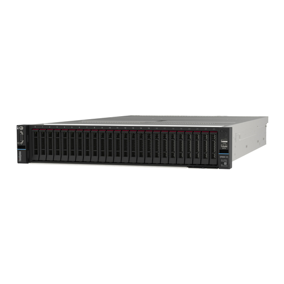
- Page 23 Table 5. Components on the front of the server (continued) Callout Callout “Front I/O module (on media bay)” on page 15 “Rack latch (right)” on page 15 “Pull-out information tab” on page 15 “Drive bays” on page 14 “Rack latch (left)” on page 15 Front view with twenty-four 2.5-inch front drive bays Table 6.
- Page 24 Blinking yellow (blinking rapidly, about four The drive is being identified. flashes per second) External diagnostics connector The connector is for connecting an external diagnostics handset. For more about its functions, see “External diagnostics handset” on page 200. ThinkSystem SR665 V3 User Guide...
-
Page 25: Front I/O Module
“Front I/O module” on page Pull-out information tab The Lenovo XClarity Controller network access label is attached on the pull-out information tab. The default Lenovo XClarity Controller hostname and the IPv6 Link Local Address (LLA) are provided on the tab. - Page 26 ID button, the state of the system ID LED changes. The LED can be changed to on, blinking, or off. You can also use the Lenovo XClarity Controller or a remote management program to change the state of the system ID LED to assist in visually locating the server among other servers.
-
Page 27: Rear View
Description Action Yellow An error has been detected on the server. • Check the Lenovo XClarity Controller Causes might include but are not limited to event log and the system event log to the following errors: determine the exact cause of the error. - Page 28 NMI button Use this button only when you are directed to do so by Lenovo Support. Press this button to force a nonmaskable interrupt (NMI) to the processor. By this way, you can make the operating system halt (such as Windows Blue Screen of Death) and take a memory dump.
-
Page 29: Top View
VGA connector. XCC system management port The server has a 1 GB RJ-45 connector dedicated to Lenovo XClarity Controller (XCC) functions. Through the system management port, you can access the Lenovo XClarity Controller directly by connecting your laptop to the management port using an Ethernet cable. -
Page 30: System-Board-Assembly Layout
This section provides information about the connectors, switches, and jumpers that are available on the system board assembly. The following illustration shows the layout of the system board assembly that contains the firmware and RoT security module, system I/O board, and processor board. ThinkSystem SR665 V3 User Guide... -
Page 31: System-Board-Assembly Connectors
Figure 6. System-board-assembly layout Firmware and RoT security module Processor board System I/O board For information about the LEDs that are available on the system board assembly, see: • “System-board-assembly LEDs” on page 209 • “LEDs on the firmware and RoT security module” on page 211 •... - Page 32 PCIe connector 9 / SATA connector 2 PCIe connector 2 PCIe connector 1 Fan 1-6 connectors Front I/O connector for Y cable note Front I/O connector note Backplane 3 power connector Backplane 2 power connector ThinkSystem SR665 V3 User Guide...
-
Page 33: System-Board-Assembly Switch
Table 12. System-board-assembly connectors (continued) CFF retimer connector CFF expander power connector Intrusion switch connector Backplane 1 power connector CFF RAID/HBA power connector External LCD connector Front VGA connector PCIe connector 4 PCIe connector 3 PCIe connector 7 / SATA connector 1 PCIe connector 5 / SATA connector 0 PCIe connector 6 Power supply 1 connector... - Page 34 ON position. SW5-4 FPGA reset Forces FPGA into reset when changing it to the ON position. SW5-5 SW5-6 MFG mode Enables MFG mode of firmware (UEFI/XCC/FPGA) when changing it to the ON position. ThinkSystem SR665 V3 User Guide...
-
Page 35: System Leds And Diagnostics Display
Table 13. Switch block on the system board assembly (continued) Switch Default position Description number Switch name SW5-7 At-Scale debug Enables BMC At-Scale debug when changing it to the ON position. SW5-8 Low security Allows transitioning between signed official XCC builds and XCC test signed builds, and bypasses CRTM boot check of XCC firmware when changing it to the ON position. - Page 36 ThinkSystem SR665 V3 User Guide...
-
Page 37: Chapter 3. Parts List
3. Enter the serial number to view a listing of parts for your server. Note: Depending on the model, your server might look slightly different from the illustration. Some parts are available only on some models. © Copyright Lenovo 2022... - Page 38 Tier 1 CRU at your request with no service agreement, you will be charged for the installation. • Tier 2 customer replaceable unit (CRU): You may install a Tier 2 CRU yourself or request Lenovo to install it, at no additional charge, under the type of warranty service that is designated for your server.
- Page 39 Table 14. Parts list Consumable Description and structural Index Tier 1 CRU Tier 2 CRU parts Top cover √ Rear wall brackets √ Power supply unit √ OCP module √ RAID flash power module √ Intrusion switch √ System fan √...
- Page 40 Firmware and RoT security √ module PCIe adapter √ Riser 3 cage (2FH) √ Riser 1 or riser 2 cage (3FH) √ Riser 3 card (2FH) √ Riser 1 or riser 2 card (3FH) √ ThinkSystem SR665 V3 User Guide...
-
Page 41: 3.5-Inch Drive Bay Chassis
For more information about ordering parts: 1. Go to and navigate to the support page for your server. http://datacentersupport.lenovo.com 2. Click Parts. 3. Enter the serial number to view a listing of parts for your server. Note: Depending on the model, your server might look slightly different from the illustration. Some parts are available only on some models. - Page 42 Tier 1 CRU at your request with no service agreement, you will be charged for the installation. • Tier 2 customer replaceable unit (CRU): You may install a Tier 2 CRU yourself or request Lenovo to install it, at no additional charge, under the type of warranty service that is designated for your server.
-
Page 43: Power Cords
Several power cords are available, depending on the country and region where the server is installed. To view the power cords that are available for the server: 1. Go to: http://dcsc.lenovo.com/#/ 2. Click Preconfigured Model or Configure to order. 3. Enter the machine type and model for your server to display the configurator page. - Page 44 The cord set should have the appropriate safety approvals for the country in which the equipment will be installed. • Power cords for a specific country or region are usually available only in that country or region. ThinkSystem SR665 V3 User Guide...
-
Page 45: Chapter 4. Unboxing And Setup
They might be required to receive warranty service. Identify the server and access the Lenovo XClarity Controller This section contains instruction on how to identify your server and where to find the Lenovo XClarity Controller access information. -
Page 46: Server Setup Checklist
Lenovo XClarity Controller network access label The Lenovo XClarity Controller (XCC) network access label is attached to the pull-out information tab located near the lower right corner in the front of the chassis, with MAC address accessible with a pull. After you receive the server, peel the XCC network access label away and store it in a safe place. - Page 47 • You can press the power button. • The server can restart automatically after a power interruption. • The server can respond to remote power-on requests sent to the Lenovo XClarity Controller. Note: You can access the management processor interface to configure the system without powering on the server.
- Page 48 The following information is available for RAID configuration: • https://lenovopress.lenovo.com/lp0578-lenovo-raid-introduction • https://lenovopress.lenovo.com/lp0579-lenovo-raid-management-tools-and-resources 4. Install the operating system. 5. Back up the server configuration. 6. Install the applications and programs for which the server is intended to be used. ThinkSystem SR665 V3 User Guide...
-
Page 49: Chapter 5. Hardware Replacement Procedures
• Do not attempt to lift an object that might be too heavy for you. If you have to lift a heavy object, read the following precautions carefully: – Make sure that you can stand steadily without slipping. © Copyright Lenovo 2022... -
Page 50: Safety Inspection Checklist
1 & IEC 60950-1, the standard for Safety of Electronic Equipment within the Field of Audio/Video, Information Technology and Communication Technology. Lenovo assumes you are qualified in the servicing of equipment and trained in recognizing hazards energy levels in products. Access to the equipment is by the use of a tool, lock and key, or other means of security, and is controlled by the authority responsible for the location. -
Page 51: System Reliability Guidelines
Click Power ➙ Power Cables to see all line cords. • Make sure that the insulation is not frayed or worn. 3. Check for any obvious non-Lenovo alterations. Use good judgment as to the safety of any non-Lenovo alterations. -
Page 52: Working Inside The Server With The Power On
Never place the device on the server or on any metal surface. • When handling a device, carefully hold it by the edges or the frame. • Do not touch solder joints, pins, or exposed circuitry. ThinkSystem SR665 V3 User Guide... -
Page 53: Technical Rules
• Keep the device from others’ reach to prevent possible damages. Technical rules This topic provides technical rules for the server. • “Memory module installation rules and order” on page 44 • “PCIe slots and PCIe adapters” on page 46 •... -
Page 54: Memory Module Installation Rules And Order
“Technical specifications” on page Your server has 24 memory slots with 24 channels. For a list of supported memory options, see: https://serverproven.lenovo.com/ Information about optimizing memory performance and configuring memory is available at the Lenovo Press website: https://lenovopress.lenovo.com/servers/options/memory In addition, you can take advantage of a memory configurator, which is available at the following site: https://dcsc.lenovo.com/#/memory_configuration... - Page 55 Memory module installation guideline Follow the rules below when installing DIMMs: • Mixing DIMMs from different vendors is supported in a system. • Mixing x4 and x8 DIMMs is not allowed in a system. • Only one rank and two rank DIMM mixing is allowed in a system. •...
-
Page 56: Pcie Slots And Pcie Adapters
The following table lists the recommended slot installation priority for common PCIe adapters. Maximum PCIe adapter Suggested slot priority supported Internal SFF RAID/HBA adapter 440-16i, 540–8i, 940-8i, 940-16i • 1 processor: 2, 3, 1 • 2 processors: 2, 3, 5, 6, 1, 4 NIC adapter ThinkSystem SR665 V3 User Guide... -
Page 57: Thermal Rules
Maximum PCIe adapter Suggested slot priority supported ThinkSystem Broadcom 5719 1GbE RJ45 4- • 1 processor: PCIe slot 2, 3, 1 Port PCIe Ethernet Adapter • 2 processors: PCIe slot 5, 2, 6, 3, 7, 8, 4, 1 ThinkSystem Mellanox ConnectX-6 Lx 10/ 25GbE SFP28 2-port PCIe Ethernet Adapter ThinkSystem Broadcom 57414 10/25GbE SFP28 2-port PCIe Ethernet Adapter V2... -
Page 58: Power On And Power Off The Server
Power off the server The server remains in a standby state when it is connected to a power source, allowing the Lenovo XClarity Controller to respond to remote power-on requests. To remove all power from the server (power status LED off), you must disconnect all power cables. -
Page 59: Server Replacement
“Troubleshooting by system LEDs and diagnostics display” on page 198 To place the server in a standby state (power status LED flashes once per second): Note: The Lenovo XClarity Controller can place the server in a standby state as an automatic response to a critical system failure. - Page 60 Rack front Figure 14. Disengaging server from the rack Rack latch Thumbscrew Step 2. Hold the mounting ears on the front of the server; then, slide the server all the way out until it stops. ThinkSystem SR665 V3 User Guide...
- Page 61 Figure 15. Pulling out the server Rack latch (Mounting ear) Step 3. Remove the server from the rack. CAUTION: Make sure three people are lifting the sever by holding the lift points. Rack front Figure 16. Lifting up the server Lift point Chapter 5 Hardware replacement procedures...
-
Page 62: Install The Server To Rack
Follow instructions in this section to install the server to the rack. S036 18 - 32 kg (39 - 70 lb) 32 - 55 kg (70 - 121 lb) CAUTION: Use safe practices when lifting. R006 ThinkSystem SR665 V3 User Guide... - Page 63 Make sure to have three people operate the server installation procedures to prevent injury. Firmware and driver download: You might need to update the firmware or driver after replacing a component. • Go to https://datacentersupport.lenovo.com/tw/en/products/servers/thinksystem/sr665v3/7d9a/downloads/ driver-list/ to see the latest firmware and driver updates for your server. • Go to “Update the firmware”...
- Page 64 Make sure three people are lifting the sever by holding the lift points. Rack front Figure 19. Lifting up the server Lift point Step 3. From the front of the rack, install the server into the rails. ThinkSystem SR665 V3 User Guide...
- Page 65 Rack front Figure 20. Installing the server into the rails Tilt the server and slowly lower its rear end; then, push the rails toward the server and make sure the farthest nailheads on server’s left and right side go into the slots on the rail. Slowly lower the server down and make sure the other three nailheads on server’s left and right sides slip into corresponding slots.
- Page 66 Figure 22. Securing the server to the rear of the rack Fasten the two thumbscrews located on the front of the server. Rack front Figure 23. Securing the server to the front of the rack Rack latch Thumbscrew After you finish ThinkSystem SR665 V3 User Guide...
-
Page 67: Air Baffle Replacement
1. Reconnect the power cords and any cables that you removed. 2. Power on the server and any peripheral devices. See “Power on the server” on page 3. Update the server configuration. See “Complete the parts replacement” on page 164. Air baffle replacement Follow instructions in this section to remove and install the air baffle. - Page 68 Figure 24. Removing the air baffle Step 3. (Optional) Remove the fillers from the air baffle if you are using performance heat sinks and need to change to 2U standard heat sinks. Figure 25. Removing the air baffle filler ThinkSystem SR665 V3 User Guide...
-
Page 69: Install The Air Baffle
After you finish If you are instructed to return the component or optional device, follow all packaging instructions, and use any packaging materials for shipping that are supplied to you. Install the air baffle Follow instructions in this section to install the air baffle. About this task S033 CAUTION:... - Page 70 Then, lower the air baffle into the chassis and press the air baffle down until it is securely seated. Figure 27. Installing the air baffle After you finish 1. Reconnect the cable of the RAID flash power module if you have disconnected it. See Chapter 6 “Internal cable routing” on page 167. ThinkSystem SR665 V3 User Guide...
-
Page 71: Cmos Battery (Cr2032) Replacement
The following tips describe information that you must consider when removing the CMOS battery. • Lenovo has designed this product with your safety in mind. The lithium CMOS battery must be handled correctly to avoid possible danger. If you replace the CMOS battery, you must adhere to local ordinances or regulations for battery disposal. - Page 72 • Failing to remove the CMOS battery properly might damage the socket on the processor board. Any damage to the socket might require replacing the processor board. • Do not tilt or push the CMOS battery by using excessive force. ThinkSystem SR665 V3 User Guide...
-
Page 73: Install The Cmos Battery
The following tips describe information that you must consider when installing the CMOS battery. • Lenovo has designed this product with your safety in mind. The lithium CMOS battery must be handled correctly to avoid possible danger. If you replace the CMOS battery, you must adhere to local ordinances or regulations for battery disposal. - Page 74 When replacing the lithium battery, use only Lenovo specified part number or an equivalent type battery recommended by the manufacturer. If your system has a module containing a lithium battery, replace it only with the same module type made by the same manufacturer. The battery contains lithium and can explode if not properly used, handled, or disposed of.
-
Page 75: Front Drive Backplane Replacement
Figure 29. Installing the CMOS battery Tilt the battery and insert it to the positive end on the socket. Make sure that the battery goes tight to the metal clip. Press the battery down until it clicks into the socket. After you finish 1. - Page 76 Record the cable connections on the backplane and then disconnect the cables from the backplane first if needed. Step 3. Remove the 2.5-inch drive backplane. Note: Depending on the specific type, your backplane might look different from the illustration. ThinkSystem SR665 V3 User Guide...
-
Page 77: Install The Front 2.5-Inch Drive Backplane
Figure 30. Removing the 8-bay drive backplane Lift all release tabs. Rotate the backplane from the top to disengage it from the pins on the chassis. After you finish If you are instructed to return the component or optional device, follow all packaging instructions, and use any packaging materials for shipping that are supplied to you. - Page 78 Then, take the new part out of the package and place it on a static-protective surface. Step 2. Install the 2.5-inch drive front backplane. Note: Depending on the specific type, your backplane might look different from the illustration. ThinkSystem SR665 V3 User Guide...
- Page 79 Figure 32. Installing the 8-bay drive backplane Align the bottom of the backplane with the slots on the chassis, and lower the backplane into the chassis. Rotate the backplane to the vertical position. Align the holes in the backplane with the pins on the chassis, and press the backplane into position.
-
Page 80: Remove The Front 3.5-Inch Drive Backplane
Record the cable connections on the backplane and then disconnect the cables from the backplane first if needed. Step 3. Remove the 3.5-inch drive backplane. Note: Depending on the specific type, your backplane might look different from the illustration. ThinkSystem SR665 V3 User Guide... -
Page 81: Install The Front 3.5-Inch Drive Backplane
Firmware and driver download: You might need to update the firmware or driver after replacing a component. • Go to https://datacentersupport.lenovo.com/tw/en/products/servers/thinksystem/sr665v3/7d9a/downloads/ driver-list/ to see the latest firmware and driver updates for your server. Chapter 5 Hardware replacement procedures... - Page 82 “Install a hot-swap drive” on page 2. Reinstall the fan cage. See “Install the system fan cage” on page 160. 3. Reinstall the air baffle if you have removed it. See “Install the air baffle” on page ThinkSystem SR665 V3 User Guide...
-
Page 83: Front I/O Module Replacement
4. Complete the parts replacement. See “Complete the parts replacement” on page 164. Front I/O module replacement Follow instructions in this section to remove and install the front I/O module. The front I/O module varies by model. The front I/O module for most models is on the right rack latch. The front I/O module on media bay is supported only in the following server models: •... - Page 84 1. Press the release tab to release the connector. 2. Disengage the connector from the cable socket. Figure 35. Disconnecting cables from the system board assembly Step 3. Remove the front I/O module from the front chassis. ThinkSystem SR665 V3 User Guide...
-
Page 85: Install The Front I/O Module
Figure 36. Removing the front I/O module Remove the screw that secure the front I/O module. Slide the front I/O module out of the front chassis. After you finish If you are instructed to return the component or optional device, follow all packaging instructions, and use any packaging materials for shipping that are supplied to you. - Page 86 1. Connect the cables of the front I/O module to the system board assembly. See Chapter 6 “Internal cable routing” on page 167. 2. Complete the parts replacement. See “Complete the parts replacement” on page 164. ThinkSystem SR665 V3 User Guide...
-
Page 87: Hot-Swap Drive Replacement
Hot-swap drive replacement Follow instructions in this section to remove and install a hot-swap drive. You can remove or install a hot- swap drive without turning off the server, which helps you avoid significant interruption to the operation of the system. •... -
Page 88: Install A Hot-Swap Drive
• To make sure that there is adequate system cooling, do not operate the server for more than two minutes without either a drive or a drive bay filler installed in each bay. ThinkSystem SR665 V3 User Guide... - Page 89 1. Reinstall the security bezel if you have removed it. See “Install the security bezel” on page 138. 2. Use the Lenovo XClarity Provisioning Manager to configure the RAID if necessary. See https:// sysmgt.lenovofiles.com/help/topic/lxpm_frontend/lxpm_product_page.html 3. If you have installed U.3 NVMe drives on a 2.5-inch AnyBay 8-bay backplane for Tri-mode, enable U.3 x1 mode for the selected drive slots on the backplane through the XCC Web GUI.
-
Page 90: Intrusion Switch Replacement
155. Remove the fan cage from the system board assembly. See “Remove the system fan cage” on page 159. Step 2. Rotate the fan cage by 90 degrees in the direction shown in the picture. ThinkSystem SR665 V3 User Guide... - Page 91 Figure 38. Rotating the fan cage Step 3. Remove the intrusion switch assembly from the fan cage. Figure 39. Removing the intrusion switch Move the intrusion switch connector in the shown direction to disengage it from the keyhole. Release the intrusion switch cable from the pre-cut slots on the foam and fan cage bottom. Release the intrusion switch cable from the cable clip.
-
Page 92: Install The Intrusion Switch
Otherwise, the cable may slide under the fan cage, the contact surface between the fan cage and the system board assembly may get uneven, and the fan connection may get loose. ThinkSystem SR665 V3 User Guide... -
Page 93: M.2 Drive And M.2 Backplane Replacement
Insert the intrusion switch onto the holder on the fan cage and push it in the direction as shown until it is fully seated. Fix the intrusion switch cable into the cable clip. Route the cable into the fan cage through the pre-cut slots on the foam and fan cage bottom. -
Page 94: Install An M.2 Drive
Install an M.2 drive Follow instructions in this section to install an M.2 drive. Attention: • Read “Installation Guidelines” on page 39 “Safety inspection checklist” on page 40 to ensure that you work safely. ThinkSystem SR665 V3 User Guide... - Page 95 Firmware and driver download: You might need to update the firmware or driver after replacing a component. • Go to https://datacentersupport.lenovo.com/tw/en/products/servers/thinksystem/sr665v3/7d9a/downloads/ driver-list/ to see the latest firmware and driver updates for your server. • Go to “Update the firmware”...
-
Page 96: Remove The M.2 Backplane
“Safety inspection checklist” on page 40 to ensure that you work safely. • Power off the server and peripheral devices and disconnect the power cords and all external cables. See “Power off the server” on page ThinkSystem SR665 V3 User Guide... - Page 97 • Prevent exposure to static electricity, which might lead to system halt and loss of data, by keeping static- sensitive components in their static-protective packages until installation, and handling these devices with an electrostatic-discharge wrist strap or other grounding system. •...
-
Page 98: Install The M.2 Backplane
• Go to “Update the firmware” on page 189 for more information on firmware updating tools. Watch the procedure A video of this procedure is available at YouTube: https://www.youtube.com/playlist?list=PLYV5R7hVcs- DR4X1YAcp9wFKhwj_tLQ5Y ThinkSystem SR665 V3 User Guide... - Page 99 Procedure Step 1. Touch the static-protective package that contains the new part to any unpainted surface on the outside of the server. Then, take the new part out of the package and place it on a static-protective surface. Step 2. Install the M.2 backplane.
-
Page 100: Memory Module Replacement
See “Remove the server from rack” on page Remove the top cover. See “Remove the top cover” on page 161. Remove the air baffle. See “Remove the air baffle” on page ThinkSystem SR665 V3 User Guide... -
Page 101: Install A Memory Module
Locate the memory module slots and determine which memory module you want to remove from the server. Step 2. Remove the memory module from the slot. Attention: To avoid breaking the retaining clips or damaging the memory module slots, handle the clips gently. - Page 102 • If there is a gap between the memory module and the retaining clips, the memory module has not been correctly inserted. In this case, open the retaining clips, remove the memory module, and then reinsert it. ThinkSystem SR665 V3 User Guide...
-
Page 103: Ocp Module Replacement
Figure 50. Installing the memory module Gently open the retaining clip on each end of the memory module slot. Align the memory module with the slot, and gently place the memory module on the slot with both hands. Firmly press both ends of the memory module straight down into the slot until the retaining clips snap into the locked position. - Page 104 Remove the OCP module. Figure 51. Removing the OCP module Loosen the thumbscrew that secures the module. Pull out the OCP module. Step 2. (Optional) Remove the OCP label. Figure 52. Removing the OCP label After you finish ThinkSystem SR665 V3 User Guide...
-
Page 105: Install The Ocp Module
1. Install a new OCP module or an OCP module filler. 2. If you are instructed to return the component or optional device, follow all packaging instructions, and use any packaging materials for shipping that are supplied to you. Install the OCP module Follow instructions in this section to install the OCP module. -
Page 106: Pcie Adapter And Riser Assembly Replacement
Ethernet card, a host bus adapter, a RAID adapter, an add-in PCIe SSD adapter, or any other supported PCIe adapters. PCIe adapters vary by type, but the installation and removal procedures are the same. The server supports the following riser cages: ThinkSystem SR665 V3 User Guide... -
Page 107: Remove A Riser Assembly
Table 19. Riser cages Server rear configuration Riser 1 cage Riser 2 cage Riser 3 cage 2FH riser cage 3FH riser cage Configuration with 8 PCIe slots Configuration with a 4 x 2.5-inch rear drive cage • “Remove a riser assembly” on page 97 •... - Page 108 Grasp the riser assembly by its edges and carefully lift it straight up and off the chassis. • Riser 3 assembly Grasp the riser assembly by its edges and carefully lift it straight up and off the chassis. ThinkSystem SR665 V3 User Guide...
-
Page 109: Remove A Pcie Adapter
Figure 56. Removing the riser 3 assembly After you finish 1. Remove the PCIe adapter from the riser assembly. See “Remove a PCIe adapter” on page 2. If you are instructed to return the component or optional device, follow all packaging instructions, and use any packaging materials for shipping that are supplied to you. - Page 110 Rotate the PCIe adapter retention latch to the open position. Grasp the PCIe adapter by its edges and carefully pull it out of the PCIe slot. Step 3. (Optional) If you are replacing the riser card, remove the riser card from the riser cage. ThinkSystem SR665 V3 User Guide...
-
Page 111: Install A Pcie Adapter
Figure 59. Removing the riser card from riser 1 cage or riser 2 cage Figure 60. Removing the riser card from riser 3 cage Loosen the screws that secure the riser card. Grasp the riser card by its edges and carefully take it out of the riser bracket in the shown direction. - Page 112 Then, take the new part out of the package and place it on a static-protective surface. Step 2. (Optional) If you have removed the riser card, install the riser card first. Figure 61. Installing the riser card to riser 1 or 2 cage ThinkSystem SR665 V3 User Guide...
- Page 113 Figure 62. Installing the riser card to riser 3 cage Align the riser card with the riser cage and put it into the riser cage in the shown direction. Install the screws to secure the riser card into place. Step 3. Install the new PCIe adapter to the riser assembly.
-
Page 114: Install A Riser Assembly
Watch the procedure A video of this procedure is available at YouTube: https://www.youtube.com/playlist?list=PLYV5R7hVcs- DR4X1YAcp9wFKhwj_tLQ5Y Procedure Step 1. Install the riser assembly into the chassis. • Riser 1 assembly (same for riser 2 assembly) ThinkSystem SR665 V3 User Guide... - Page 115 Figure 65. Installing the riser 1 assembly Align the riser card with the riser slot on the system board assembly. Carefully press the riser card straight into the slot until it is securely seated. Tighten the screw to secure the riser cage. •...
-
Page 116: Power Supply Unit Replacement
Safety precautions for AC power supplies The following tips describe the information that you must consider when you replace an AC power supply. ThinkSystem SR665 V3 User Guide... - Page 117 S035 CAUTION: Never remove the cover on a power supply or any part that has this label attached. Hazardous voltage, current, and energy levels are present inside any component that has this label attached. There are no serviceable parts inside these components. If you suspect a problem with one of these parts, contact a service technician. S002 CAUTION: The power-control button on the device and the power switch on the power supply do not turn off the electrical...
-
Page 118: Remove A Power Supply Unit
Before removing it, you must turn off the server first. To support redundancy mode or hot-swap, install an additional hot-swap power supply unit. Attention: • Read “Installation Guidelines” on page 39 “Safety inspection checklist” on page 40 to ensure that you work safely. ThinkSystem SR665 V3 User Guide... - Page 119 • Prevent exposure to static electricity, which might lead to system halt and loss of data, by keeping static- sensitive components in their static-protective packages until installation, and handling these devices with an electrostatic-discharge wrist strap or other grounding system. Watch the procedure A video of this procedure is available at YouTube: https://www.youtube.com/playlist?list=PLYV5R7hVcs-...
-
Page 120: Install A Power Supply Unit
• Attach the power information label that comes with this option onto the existing label near the power supply unit. Figure 69. Example power supply unit label on the top cover Attention: • Read “Installation Guidelines” on page 39 “Safety inspection checklist” on page 40 to ensure that you work safely. ThinkSystem SR665 V3 User Guide... - Page 121 • Prevent exposure to static electricity, which might lead to system halt and loss of data, by keeping static- sensitive components in their static-protective packages until installation, and handling these devices with an electrostatic-discharge wrist strap or other grounding system. Watch the procedure A video of this procedure is available at YouTube: https://www.youtube.com/playlist?list=PLYV5R7hVcs-...
-
Page 122: Processor And Heat Sink Replacement
Follow instructions in this section to remove and install a processor or a heat sink. Important: • This task must be operated by trained technicians that are certified by Lenovo Service. Do no attempt to remove or install it without proper training and qualification. -
Page 123: Remove A Heat Sink
Figure 71. Processor and heat sink components Captive screws (6) Processor contacts Heat sink Processor triangular mark Processor identification label Carrier triangular mark Heat sink triangular mark Processor carrier Screw bolts (6) Processor heat spreader Retention frame triangular mark Thermal grease •... - Page 124 About this task Important: This task must be operated by trained technicians that are certified by Lenovo Service. Do no attempt to remove or install it without proper training and qualification. S002 CAUTION: The power-control button on the device and the power switch on the power supply do not turn off the electrical current supplied to the device.
- Page 125 Figure 72. Removing a standard heat sink Figure 73. Removing a performance heat sink Fully loosen all the screws on the heat sink in the removal sequence shown on the heat- sink label. Carefully lift the heat sink from the processor socket. After you finish •...
-
Page 126: Remove A Processor
Follow instructions in this section to remove a processor. This task requires a Torx T20 driver. About this task Important: This task must be operated by trained technicians that are certified by Lenovo Service. Do no attempt to remove or install it without proper training and qualification. -
Page 127: Install A Processor
Follow instructions in this section to install a processor. This task requires a Torx T20 driver. About this task Important: This task must be operated by trained technicians that are certified by Lenovo Service. Do no attempt to remove or install it without proper training and qualification. - Page 128 (Optional) Remove the processor socket cover. The procedure of removing the processor socket cover is the same as that of removing a processor. See “Remove a processor” on page 116. Step 3. Install the processor. ThinkSystem SR665 V3 User Guide...
-
Page 129: Install A Heat Sink
Follow the instructions in this section to install a heat sink. This task requires a Torx T20 driver. About this task Important: This task must be operated by trained technicians that are certified by Lenovo Service. Do no attempt to remove or install it without proper training and qualification. - Page 130 0.1 ml of thermal grease. Figure 78. Applying thermal grease Step 3. Install the heat sink. Note: For reference, the torque required for the fasteners to fully tighten is 1.22-1.46 newton- meters (10.8-13.0 inch-pounds). ThinkSystem SR665 V3 User Guide...
- Page 131 Figure 79. Installing a standard heat sink Figure 80. Installing a performance heat sink Align the triangular mark and screws on the heat sink with the triangular mark and threaded posts on the processor socket; then install the heat sink on the processor socket. Fully tighten all the screws in the installation sequence shown on the heat-sink label.
-
Page 132: Rack Latches Replacement
I/O board. • The connectors on your system board assembly might look different from those in the illustration, but the removal procedure is the same. 1. Press the release tab to release the connector. ThinkSystem SR665 V3 User Guide... - Page 133 2. Disengage the connector from the cable socket. Figure 81. Disconnecting cables from the system board assembly Step 3. Remove the screws that secure the cable retainer on the side of the server. Then, remove the cable retainer from the chassis. Figure 82.
- Page 134 Figure 84. Removing the rack latch After you finish If you are instructed to return the component or optional device, follow all packaging instructions, and use any packaging materials for shipping that are supplied to you. ThinkSystem SR665 V3 User Guide...
-
Page 135: Install The Rack Latches
Install the rack latches Follow instructions in this section to install the rack latches. About this task Attention: • Read “Installation Guidelines” on page 39 “Safety inspection checklist” on page 40 to ensure that you work safely. • Power off the server and peripheral devices and disconnect the power cords and all external cables. See “Power off the server”... - Page 136 Note: To avoid unnecessary damage to the bundle cable, ensure that it is routed and fixed on the upper frame of the cable retainer and does not cover the screw holes. ThinkSystem SR665 V3 User Guide...
-
Page 137: Raid Flash Power Module Replacement
Figure 87. Installing the cable retainer Step 5. Connect the cables to the system board assembly. See Chapter 6 “Internal cable routing” on page 167. After you finish 1. Install the air baffle. See “Install the air baffle” on page 2. - Page 138 Install a RAID flash power module on the air baffle Follow instructions in this section to install a RAID flash power module (also called supercap) on the air baffle. About this task Attention: ThinkSystem SR665 V3 User Guide...
-
Page 139: Rearwall Bracket Replacement
• Read “Installation Guidelines” on page 39 “Safety inspection checklist” on page 40 to ensure that you work safely. • Power off the server and peripheral devices and disconnect the power cords and all external cables. See “Power off the server” on page •... -
Page 140: Remove A Rearwall Bracket
If the server is installed in a rack, slide the server out on its rack slide rails to gain access to the top cover, or remove the server from the rack. See “Remove the server from rack” on page ThinkSystem SR665 V3 User Guide... - Page 141 Remove the top cover. See “Remove the top cover” on page 161. Remove the riser assembly or rear drive cage. • “PCIe adapter and riser assembly replacement” on page 96 • “Rear drive backplane and drive cage replacement” on page 134 Step 2.
-
Page 142: Install A Rearwall Bracket
Then, take the new part out of the package and place it on a static-protective surface. Step 2. Install the rearwall brackets. Align the rearwall bracket with the chassis, and insert the bracket into place. Install the screws to secure the rearwall bracket. ThinkSystem SR665 V3 User Guide... - Page 143 Note: The illustrations show installing the A1, B1, and C1 rearwall brackets. The procedure is the same for installing other rearwall brackets. Figure 93. Installing the A1 rearwall bracket (left) Figure 94. Installing the B1 rearwall bracket (middle) Figure 95. Installing the C1 rearwall bracket (right) Chapter 5 Hardware replacement procedures...
-
Page 144: Replacement
161. Disconnect cables from the rear drive backplane. Remove all the installed drives and fillers (if any) from the drive bays. See “Remove a hot-swap drive” on page Step 2. Remove the rear drive cage. ThinkSystem SR665 V3 User Guide... - Page 145 Figure 96. Removing the 4 x 2.5-inch rear drive cage Twist and pull out the blue plungers. Slide the drive cage towards the rear of the chassis to release it, and lift the drive cage out of the chassis. Step 3. Remove the rear drive backplane.
-
Page 146: Cage
Install the drive backplane into the rear drive cage. Figure 98. Installing the 4 x 2.5-inch rear drive backplane Align the bottom of the backplane with the studs at the bottom of the drive cage. ThinkSystem SR665 V3 User Guide... -
Page 147: Security Bezel Replacement
Lower the backplane into the drive cage so that the holes in the backplane pass through the pins on the drive cage, and press the backplane into position. The release latches will secure the backplane in place. Step 3. Install the rear drive cage. Figure 99. -
Page 148: Install The Security Bezel
“Installation Guidelines” on page 39 “Safety inspection checklist” on page 40 to ensure that you work safely. • Before you ship the rack with the server installed, reinstall and lock the security bezel into place. ThinkSystem SR665 V3 User Guide... - Page 149 Watch the procedure A video of this procedure is available at YouTube: https://www.youtube.com/playlist?list=PLYV5R7hVcs- DR4X1YAcp9wFKhwj_tLQ5Y Procedure Step 1. If the key is held inside the security bezel, remove it out of the security bezel. Figure 102. Removing the key Step 2. Carefully insert the tabs on the security bezel into the slots on the right rack latch.
-
Page 150: System Board Assembly Replacement
Follow instructions in this section to remove and install the system board assembly. Important: • This task must be operated by trained technicians that are certified by Lenovo Service. Do no attempt to remove or install it without proper training and qualification. -
Page 151: Remove The Firmware And Rot Security
Follow instructions in this section to remove the ThinkSystem V3 Firmware and Root of Trust Security Module (firmware and RoT security module). About this task Important: This task must be operated by trained technicians that are certified by Lenovo Service. Do no attempt to remove or install it without proper training and qualification. Attention: •... - Page 152 Remove the firmware and RoT security module. Figure 106. Removing the firmware and RoT security module Loosen the two screws on the firmware and RoT security module. Lift the firmware and RoT security module out of the chassis. After you finish ThinkSystem SR665 V3 User Guide...
-
Page 153: Install The Firmware And Rot Security
Follow instructions in this section to install the ThinkSystem V3 Firmware and Root of Trust Security Module (firmware and RoT security module). About this task Important: This task must be operated by trained technicians that are certified by Lenovo Service. Do no attempt to remove or install it without proper training and qualification. Attention: •... - Page 154 TPM is enabled by default to encrypt data transfer for system operation. Optionally, you can disable TPM using Lenovo XClarity Essentials OneCLI. To disable TPM, do the following: 1. Download and install Lenovo XClarity Essentials OneCLI. To download Lenovo XClarity Essentials OneCLI, go to the following site: https://datacentersupport.lenovo.com/solutions/HT116433 ThinkSystem SR665 V3 User Guide...
- Page 155 Follow the procedure below to see the TPM firmware version: From Lenovo XClarity Provisioning Manager 1. Start the server and press the key specified in the on-screen instructions to display the Lenovo XClarity Provisioning Manager interface. (For more information, see the “Startup” section in the LXPM documentation compatible with your server at https://sysmgt.lenovofiles.com/help/topic/lxpm_frontend/...
- Page 156 To enable UEFI Secure Boot from Lenovo XClarity Provisioning Manager: 1. Start the server and press the key specified in the on-screen instructions to display the Lenovo XClarity Provisioning Manager interface. (For more information, see the “Startup” section in the LXPM documentation compatible with your server at https://sysmgt.lenovofiles.com/help/topic/lxpm_frontend/...
-
Page 157: Remove The System I/O Board Or Processor
About this task Important: • This task must be operated by trained technicians that are certified by Lenovo Service. Do no attempt to remove or install it without proper training and qualification. • When replacing the system board assembly, always update the server with the latest firmware or restore the pre-existing firmware. - Page 158 Watch the procedure A video of this procedure is available at YouTube: https://www.youtube.com/playlist?list=PLYV5R7hVcs- DR4X1YAcp9wFKhwj_tLQ5Y Procedure Step 1. Make preparation for this task. ThinkSystem SR665 V3 User Guide...
-
Page 159: Board
Record all system configuration information, such as Lenovo XClarity Controller IP addresses, vital product data, and the machine type, model number, serial number, Universally Unique Identifier, and asset tag of the server. Save the system configuration to an external device with Lenovo XClarity Essentials. -
Page 160: Install The System I/O Board Or Processor
Follow instructions in this section to install the system I/O board or processor board. About this task Important: This task must be operated by trained technicians that are certified by Lenovo Service. Do no attempt to remove or install it without proper training and qualification. - Page 161 Firmware and driver download: You might need to update the firmware or driver after replacing a component. • Go to https://datacentersupport.lenovo.com/tw/en/products/servers/thinksystem/sr665v3/7d9a/downloads/ to see the latest firmware and driver updates for your server. driver-list/ • Go to “Update the firmware”...
- Page 162 I/O board onto the new system I/O board. See “Install the firmware and RoT security module” on page 143. Step 4. Install the system board assembly into the server. ThinkSystem SR665 V3 User Guide...
- Page 163 9. Update the vital product data (VPD). See “Update the Vital Product Data (VPD)” on page 154. Machine type number and serial number can be found on the ID label, see “Identify the server and access the Lenovo XClarity Controller” on page Chapter 5 Hardware replacement procedures...
- Page 164 Using Lenovo XClarity Provisioning Manager Steps: 1. Start the server and press the key according to the on-screen instructions. The Lenovo XClarity Provisioning Manager interface is displayed by default. 2. Choose System Summary. The “System Summary” tab page is displayed.
-
Page 165: System Fan Replacement
The server asset tag number.Type aaaaaaaaaaaaaaaaaaaaaaaaaaaaaaaaa, where aaaaaaaaaaaaaaaaaaaaaaaaaaaaaaaaa is the asset tag number. The access method that you select to access the target server. • Online KCS (unauthenticated and user restricted): You can directly delete [access_method] from the command. •... - Page 166 “Remove the top cover” on page 161. Step 3. Remove the system fan. Figure 112. Removing the system fan Grasp the top of the system fan with your fingers. Lift the system fan out of the server. ThinkSystem SR665 V3 User Guide...
-
Page 167: Install A System Fan
After you finish 1. Install a new system fan or install a fan filler to cover the place. See “Install a system fan” on page 157. 2. If you are instructed to return the component or optional device, follow all packaging instructions, and use any packaging materials for shipping that are supplied to you. - Page 168 Figure 113. Installing the system fan After you finish Complete the parts replacement. See “Complete the parts replacement” on page 164. ThinkSystem SR665 V3 User Guide...
-
Page 169: System Fan Cage Replacement
System fan cage replacement Follow instructions in this section to remove and install the system fan cage. • “Remove the system fan cage” on page 159 • “Install the system fan cage” on page 160 Remove the system fan cage Follow instructions in this section to remove the system fan cage. -
Page 170: Install The System Fan Cage
Watch the procedure A video of this procedure is available at YouTube: https://www.youtube.com/playlist?list=PLYV5R7hVcs- DR4X1YAcp9wFKhwj_tLQ5Y Procedure ThinkSystem SR665 V3 User Guide... -
Page 171: Top Cover Replacement
Figure 115. Installing the system fan cage Step 1. Align the system fan cage with the mounting guides on both sides of chassis, and lower it into the chassis. Step 2. Rotate the fan cage levers down until the fan cage clicks into place. Note: If there are system fans installed in the system fan cage, ensure that the system fans are correctly connected to the system fan connectors on the system board assembly. - Page 172 See “Remove the server from rack” on page Step 2. Remove the top cover. Attention: Handle the top cover carefully. Dropping the top cover with the cover latch open might damage the cover latch. ThinkSystem SR665 V3 User Guide...
-
Page 173: Install The Top Cover
Figure 116. Removing the top cover Use a screwdriver to turn the cover lock to the unlocked position as shown. Press the release button on the cover latch. The cover latch then gets released to some extent. Fully open the cover latch as shown. Slide the top cover to the rear until it is disengaged from the chassis. -
Page 174: Complete The Parts Replacement
2. Properly route and secure the cables in the server. Refer to the cable connecting and routing information for each component. 3. Reinstall the air baffle if you have removed it. See “Install the air baffle” on page ThinkSystem SR665 V3 User Guide... - Page 175 7. Power on the server and any peripheral devices. See “Power on the server” on page 8. Update the server configuration. • Download and install the latest device drivers: http://datacentersupport.lenovo.com • Update the system firmware. See “Update the firmware” on page 189.
- Page 176 ThinkSystem SR665 V3 User Guide...
-
Page 177: Chapter 6. Internal Cable Routing
“12 x 3.5-inch SAS/SATA front backplane” on page 168 • “4 x 2.5-inch SAS/SATA middle/rear backplane” on page 169 8 x 2.5-inch SAS/SATA front backplane See this section to locate the connectors on the drive backplane. © Copyright Lenovo 2022... - Page 178 Figure 119. 8 x 2.5-inch AnyBay backplane connectors NVMe 6-7 connector NVMe 4-5 connector Power connector SAS connector NVMe 2-3 connector NVMe 0-1 connector 12 x 3.5-inch SAS/SATA front backplane See this section to locate the connectors on the drive backplane. ThinkSystem SR665 V3 User Guide...
- Page 179 Figure 120. 12 x 3.5-inch SAS/SATA backplane connectors SAS 2 connector SAS 1 connector Power connector 1 SAS 0 connector Power connector 2 4 x 2.5-inch SAS/SATA middle/rear backplane See this section to locate the connectors on the drive backplane. Figure 121.
-
Page 180: Front Vga Connector And External Diagnostics
Figure 122. Cable routing for the front VGA connector and external diagnostics connector From VGA cable VGA connector on the system board assembly External diagnostics cable External LCD connector on the system board assembly ThinkSystem SR665 V3 User Guide... -
Page 181: Front I/O Module
Front I/O module This topic provides cable routing information for the front I/O module. Notes: • The front I/O module varies by model. See “Front I/O module” on page • When routing the front I/O module cable, ensure that it is fixed on the upper frame of the cable retainer. For details, see “Install the rack latches”... - Page 182 Figure 124. Cable routing for the front operator panel on the media bay From Front USB cable Front USB connector on the system board assembly Front panel cable Front I/O connectors on the system board assembly ThinkSystem SR665 V3 User Guide...
-
Page 183: Intrusion Switch
Intrusion switch This topic provides cable routing information for the intrusion switch. Figure 125. Intrusion switch cable routing From Intrusion switch cable Intrusion switch connector on the system board assembly Chapter 6 Internal cable routing... -
Page 184: M.2 Drive Backplane
M.2 power connector on the system board assembly M.2 signal cable • PCIe connector 10 on the system board assembly for SATA M.2 • M.2 signal connector on the system board assembly for NVMe M.2 ThinkSystem SR665 V3 User Guide... -
Page 185: Raid Flash Power Module
RAID flash power module This topic provides cable routing information for the RAID flash power module (also called supercap). Figure 128. Cable routing for RAID flash power module An extension cable is provided for each RAID flash power module for cable connection. Connect the cable from the RAID flash power module to the corresponding RAID adapter as shown. -
Page 186: Riser Cards
“Riser card 3 power and sideband cable connection” on page 177 • “Riser card 3 signal cable connection” on page 178 The riser card types vary by server model. For detailed information, see “PCIe slots and PCIe adapters” on page ThinkSystem SR665 V3 User Guide... - Page 187 Riser card 3 power and sideband cable connection Figure 129. Riser card 3 power and sideband cable connection From Power connector on the riser card Riser 3 power connector on the system board assembly Sideband connector on the riser card Riser 3 sideband connector on the system board assembly Chapter 6...
-
Page 188: Xgmi Links
4 xGMI links This topic provides cable routing information for 4 External Global Memory Interconnect (xGMI) links. The configuration with 4 xGMI links is applicable to two-processor system only. The following configurations support 4 xGMI links: ThinkSystem SR665 V3 User Guide... - Page 189 • Front 8 x 2.5-inch SAS/SATA with one 8i adapter • Front 12 x 3.5" SAS/SATA + Rear 4 x 2.5" SAS/SATA with one 16i adapter Figure 131. Cable routing for 4 xGMI links From PCIe connectors 2 and 1 on the system board PCIe connectors 3 and 4 on the system board assembly assembly Chapter 6...
-
Page 190: Drive Bays
Connect the power cables for the front 2.5-inch drive backplanes as illustrated. Power cable connections are the same for the following 8 x 2.5-inch front drive backplanes. • 8 x 2.5-inch SAS/SATA backplane • 8 x 2.5-inch NVMe backplane Figure 132. Power cable connections for 8 x 2.5-inch drive backplanes ThinkSystem SR665 V3 User Guide... - Page 191 From Backplane 1: PWR Backplane 1 power connector on the system board assembly Backplane 2: PWR Backplane 2 power connector on the system board assembly Backplane 3: PWR Backplane 3 power connector on the system board assembly Signal cable connections Refer to the specific topic for signal cable connections depending on the backplanes installed.
-
Page 192: One 8 X Sas/Sata Backplane
This topic provides cable routing information for the 8 x 2.5-inch SAS/SATA configuration with one 8i adapter. ↔ ↔ ↔ ↔ Connections between connectors: , ... Figure 133. SAS/SATA cable routing to 8i RAID adapter From Backplane 1: SAS 8i adapter: C0 ThinkSystem SR665 V3 User Guide... -
Page 193: Two 8 X Nvme Backplanes
Two 8 x NVMe backplanes This topic provides cable routing information for the configuration with 16 x NVMe front drives using two 8 x NVMe front backplanes. Figure 134. NVMe cable routing to onboard PCIe connectors From Backplane 1: NVMe 0-1 Onboard: PCIe 5 Backplane 1: NVMe 2-3 Onboard: PCIe 7... - Page 194 From Backplane 2: NVMe 4-5 Onboard: PCIe 2 Backplane 2: NVMe 6-7 Onboard: PCIe 1 ThinkSystem SR665 V3 User Guide...
-
Page 195: One 8 X Sas/Sata Backplane And Two 8 X
One 8 x SAS/SATA backplane and two 8 x NVMe backplanes This topic provides cable routing information for the 8 SAS/SATA + 16 NVMe configuration with one 8i adapter. ↔ ↔ ↔ ↔ Connections between connectors: , ... Figure 135. SAS/SATA cable routing Figure 136. -
Page 196: Drive Bays
Figure 137. Power cable connections for the 12 x 3.5-inch drive backplane From Power connector 1 on the backplane Backplane 1 power connector on the system board assembly Power connector 2 on the backplane Backplane 2 power connector on the system board assembly ThinkSystem SR665 V3 User Guide... - Page 197 Signal cable connections Front 12 x 3.5" SAS/SATA + Rear 4 x 2.5" SAS/SATA with one 16i adapter ↔ ↔ ↔ ↔ Connections between connectors: , ... Figure 138. Front/Rear backplane signal cable routing Figure 139. Rear backplane power cable routing From From Backplane 1: SAS 0,...
- Page 198 ThinkSystem SR665 V3 User Guide...
-
Page 199: Chapter 7. System Configuration
The following methods are available to set the network connection for the Lenovo XClarity Controller if you are not using DHCP: • If a monitor is attached to the server, you can use Lenovo XClarity Provisioning Manager to set the network connection. - Page 200 (with firmware and device driver updates) to support specific Windows Server and Red Hat Enterprise Linux (RHEL) operating system distributions. Machine-type-specific firmware-only UXSPs are also available. Firmware updating tools See the following table to determine the best Lenovo tool to use for installing and setting up the firmware: Tool Update Core...
- Page 201 • Lenovo XClarity Controller If you need to install a specific update, you can use the Lenovo XClarity Controller interface for a specific server. Notes: – To perform an in-band update through Windows or Linux, the operating system driver must be installed and the Ethernet-over-USB (sometimes called LAN over USB) interface must be enabled.
-
Page 202: Configure The Firmware
Several options are available to install and set up the firmware for the server. Important: Do not configure option ROMs to be set to Legacy unless directed to do so by Lenovo Support. This setting prevents UEFI drivers for the slot devices from loading, which can cause negative side effects for Lenovo software, such as Lenovo XClarity Essentials OneCLI, and to the Lenovo XClarity Controller. -
Page 203: Memory Module Configuration
• Lenovo XClarity Essentials OneCLI You can use the config application and commands to view the current system configuration settings and make changes to Lenovo XClarity Controller and UEFI. The saved configuration information can be used to replicate or restore other systems. -
Page 204: Deploy The Operating System
Detailed information about RAID management tools and resources is available at the following Lenovo Press website: https://lenovopress.lenovo.com/lp0579-lenovo-raid-management-tools-and-resources Deploy the operating system Several options are available to deploy an operating system on the server. Available operating systems • Microsoft Windows Server •... - Page 205 “Backing up the BMC configuration” section in the XCC documentation compatible with your server at https://sysmgt.lenovofiles.com/help/topic/lxcc_frontend/lxcc_overview.html Alternatively, you can use the command from Lenovo XClarity Essentials OneCLI to create a backup save of all configuration settings. For more information about the...
- Page 206 ThinkSystem SR665 V3 User Guide...
-
Page 207: Chapter 8. Problem Determination
An alert is a message or other indication that signals an event or an impending event. Alerts are generated by the Lenovo XClarity Controller or by UEFI in the servers. These alerts are stored in the Lenovo XClarity Controller Event Log. -
Page 208: Display
Figure 140. Lenovo XClarity Controller event log For more information about accessing the Lenovo XClarity Controller event log, see: “Viewing Event Logs” section in the XCC documentation compatible with your server at https:// sysmgt.lenovofiles.com/help/topic/lxcc_frontend/lxcc_overview.html Troubleshooting by system LEDs and diagnostics display See the following section for information on available system LEDs and diagnostics display. -
Page 209: Front Operator Panel Leds
Drive LED Status Description Drive activity LED (left) Solid green The drive is powered but not active. Blinking green The drive is active. Drive status LED (right) Solid yellow The drive has an error. The drive is being rebuilt. Blinking yellow (blinking slowly, about one flash per second) Blinking yellow (blinking rapidly, about four The drive is being identified. -
Page 210: External Diagnostics Handset
ID button, the state of the system ID LED changes. The LED can be changed to on, blinking, or off. You can also use the Lenovo XClarity Controller or a remote management program to change the state of the system ID LED to assist in visually locating the server among other servers. - Page 211 • “Options flow diagram” on page 203 • “Full menu list” on page 204 Location of the external diagnostics handset Description Location The external diagnostics handset is connected to the External diagnostics handset server with an external cable. Magnetic bottom With this component, the diagnostics handset can be attached to the top or side of the rack with hands spared for service tasks.
- Page 212 LCD display Scroll buttons (up/down/left/right) Press the scroll buttons to locate and select system information. Select button Press the select button to select from the options in the menu. ThinkSystem SR665 V3 User Guide...
- Page 213 Options flow diagram The LCD panel displays various system information. Navigate through the options with the scroll keys. Depending on the model, the options and entries on the LCD display might be different. Chapter 8 Problem determination...
- Page 214 • Possible sources of the error CPU 1 Status: Configuration Error System VPD Information Sub Menu Example Machine Type: xxxx • Machine type and serial number Serial Num: xxxxxx • Universal Unique ID (UUID) Universal Unique ID: xxxxxxxxxxxxxxxxxxxxxxxxxxxx ThinkSystem SR665 V3 User Guide...
- Page 215 System Firmware Sub Menu Example UEFI UEFI (Inactive) • Firmware level (status) Build: D0E101P • Build ID Version: 1.00 • Version number Date: 2019-12-26 • Release date XCC Primary XCC Primary (Active) • Firmware level (status) Build: DVI399T • Build ID Version: 4.07 •...
-
Page 216: Xcc System Management Port Leds
XCC system management port LEDs This topic provides information on LEDs of XCC system management port. The following table describes the problems that are indicated by LEDs on XCC system management port. Figure 143. XCC system management port LEDs ThinkSystem SR665 V3 User Guide... -
Page 217: Power Supply Leds
Description Ethernet port Use this green LED to distinguish the network connectivity status: link LED • Off: The network link is disconnected. • Green: The network link is established. Ethernet port Use this green LED to distinguish the network activity status: activity LED •... - Page 218 When the power load increases, the standby power supply will switch to active state to provide sufficient power to the server. To disable zero-output mode, log in to the Lenovo XClarity Controller web interface, choose Server Configuration ➙ Power Policy, disable Zero Output Mode, and then click Apply. If you disable zero-output mode, both power supplies will be in the active state.
-
Page 219: System-Board-Assembly Leds
System-board-assembly LEDs The following illustration shows the light-emitting diodes (LEDs) on the system board assembly that contains the system I/O board and processor board. Figure 145. System-board-assembly LEDs Table 20. System-board-assembly LEDs Description Action LED on: An error has occurred. System error LED Check system logs or internal error LEDs to identify the (yellow) - Page 220 RoT security module are installed correctly. (Trained technician only) Reinstall them if needed. 3. If the problem remains, contact Lenovo Support. System status The system status LED indicates • If the system status LED is blinking fast over 5 minutes the working status of the system.
-
Page 221: Leds On The Firmware And Rot Security
Table 20. System-board-assembly LEDs (continued) Description Action 4. If the problem still remains, contact Lenovo Support. FPGA heartbeat The FPGA heartbeat LED helps If the FPGA heartbeat LED is always off or always on, do LED (green) you identify the FPGA status. -
Page 222: General Problem Determination Procedures
3. Remove or disconnect the following devices if applicable, one at a time, until you find the failure. Power on and configure the server each time you remove or disconnect a device. • Any external devices. • Surge-suppressor device (on the server). • Printer, mouse, and non-Lenovo devices. ThinkSystem SR665 V3 User Guide... -
Page 223: Resolving Suspected Power Problems
• The cable must be securely attached at all connections. If the cable is attached but the problem remains, try a different cable. • Make sure that the cable used is supported by the adapter. For more information about the supported adapters, cables, and transceivers of the specific servers, go to https:// serverproven.lenovo.com/thinksystem/index Chapter 8 Problem determination... - Page 224 Make sure that the device drivers on the client and server are using the same protocol. If the Ethernet controller still cannot connect to the network but the hardware appears to be working, the network administrator must investigate other possible causes of the error. ThinkSystem SR665 V3 User Guide...
-
Page 225: Troubleshooting By Symptom
Use this information to find solutions to problems that have identifiable symptoms. To use the symptom-based troubleshooting information in this section, complete the following steps: 1. Check the event log of Lenovo XClarity Controller and follow the suggested actions to resolve any event codes. - Page 226 Multiple hard drives fail Complete the following steps until the problem is solved: • View the Lenovo XClarity Controller event log for events related to power supplies or vibration issues and resolve those events. • Make sure that the device drivers and firmware for the hard disk drive and server are at the latest level.
-
Page 227: Intermittent Problems
.) You can perform hard drive diagnostics from this interface. lxpm_frontend/lxpm_product_page.html From the Diagnostic page, click Run Diagnostic ➙ Disk Drive Test 2. If the drive passes the test, replace the backplane. 3. If the drive fails the test, replace the drive. Yellow hard disk drive status LED does not represent actual state of associated drive Complete the following steps until the problem is solved: 1. -
Page 228: Keyboard, Mouse, Kvm Switch Or Usb-Device
197 for information about viewing the event log. If you are using Linux base operating system, capture all logs back to Lenovo support for further investigation. Keyboard, mouse, KVM switch or USB-device problems Use this information to solve problems related to a keyboard, mouse, KVM switch or USB-device problems. -
Page 229: Problems
• The server and the monitor are turned on. 2. If you are using a USB keyboard, run the Setup utility and enable keyboardless operation. 3. If you are using a USB keyboard and it is connected to a USB hub, disconnect the keyboard from the hub and connect it directly to the server. -
Page 230: Memory Problems
4. Run the memory module diagnostics. When you start a server and press the key according to the on- screen instructions, the Lenovo XClarity Provisioning Manager interface is displayed by default. From the Diagnostic page, click Run Diagnostic ➙ Memory Test ➙ Advanced Memory Test. If any memory module fails the test, repeat steps 2 and 3. -
Page 231: Monitor And Video Problems
To use the management controller remote presence function, remove the optional video adapter. 3. If the server is installed with the graphical adapters while turning on the server, the Lenovo logo is displayed on the screen after approximately 3 minutes. This is normal operation while the system loads. -
Page 232: Observable Problems
To prevent diskette drive read/write errors, make sure that the distance between the monitor and any external diskette drive is at least 76 mm (3 in.). b. Non-Lenovo monitor cables might cause unpredictable problems. 2. Reseat the monitor cable. - Page 233 If the system hangs during the UEFI boot process with the message UEFI: DXE INIT on the display, make sure that Option ROMs were not configured with a setting of Legacy. You can remotely view the current settings for Option ROMs by running the following command using the Lenovo XClarity Essentials OneCLI: onecli config show EnableDisableAdapterOptionROMSupport --bmc xcc_userid:xcc_password@xcc_ipaddress...
- Page 234 Replace the item for which the error occurs. • If the system does not restart, suspect the processor board first and then the system I/O board. Unusual smell Complete the following steps until the problem is solved. ThinkSystem SR665 V3 User Guide...
-
Page 235: Optional-Device Problems
• “Insufficient PCIe resources are detected.” on page 226 • “A Lenovo optional device that was just installed does not work.” on page 226 • “A Lenovo optional device that worked previously does not work now” on page 227 External USB device is not recognized Complete the following steps until the problem is resolved: 1. - Page 236 9. DC cycle the system and ensure the system is enter UEFI boot menu or the operating system; then, capture the FFDC log. 10. Contact Lenovo technical support. A Lenovo optional device that was just installed does not work. 1. Make sure that: • The device is supported for the server (see https://serverproven.lenovo.com/...
-
Page 237: Performance Problems
4. Reseat the cable connection and check there is no physical damage to the cable. 5. If there is any cable damages, then replace the cable. A Lenovo optional device that worked previously does not work now 1. Make sure that all of the cable connections for the device are secure. -
Page 238: Power On And Power Off Problems
• If the server starts, reseat the front operator panel. • If the problem remains, replace the front operator panel. 2. Make sure that: • The power cords are correctly connected to the server and to a working electrical outlet. ThinkSystem SR665 V3 User Guide... -
Page 239: Power Problems
6. If everything is still done and the issue cannot be resolved, please collect the failure information with system logs captured to Lenovo support. Server does not power on Complete the following steps until the problem is resolved: 1. -
Page 240: Software Problems
2. If you receive any error messages while you use the software, see the information that comes with the software for a description of the messages and suggested solutions to the problem. 3. Contact your place of purchase of the software. ThinkSystem SR665 V3 User Guide... -
Page 241: Appendix A. Hardware Disassembling For Recycle
Remove the screws that secure the system I/O board. Lift and hold the rear lift handle and slide the system I/O board towards the rear to disengage it from the processor board. Step 4. Remove the screws from the processor board as illustrated. © Copyright Lenovo 2022... - Page 242 Figure 148. Removing screws from the processor board Tools Screw Quantity PH2 screwdriver PH2 screwdriver Hex wrench PH2 screwdriver Step 5. Remove the following components from the processor board. • Cable wall brackets • PSU air baffle ThinkSystem SR665 V3 User Guide...
- Page 243 Figure 149. Removing components from the processor board Step 6. Separate the processor board from the supporting sheet metal. Appendix A. Hardware disassembling for recycle...
- Page 244 Figure 150. Separating the processor board from the supporting sheet metal After you finish After disassembling the system board assembly, recycle the units in compliance with local regulations. ThinkSystem SR665 V3 User Guide...
-
Page 245: Appendix B. Getting Help And Technical Assistance
Appendix B. Getting help and technical assistance If you need help, service, or technical assistance or just want more information about Lenovo products, you will find a wide variety of sources available from Lenovo to assist you. On the World Wide Web, up-to-date information about Lenovo systems, optional devices, services, and support are available at: http://datacentersupport.lenovo.com... -
Page 246: Collecting Service Data
Collecting service data To clearly identify the root cause of a server issue or at the request of Lenovo Support, you might need collect service data that can be used for further analysis. Service data includes information such as event logs and hardware inventory. -
Page 247: Contacting Support
• Lenovo XClarity Essentials OneCLI Lenovo XClarity Essentials OneCLI has inventory application to collect service data. It can run both in- band and out-of-band. When running in-band within the host operating system on the server, OneCLI can collect information about the operating system, such as the operating system event log, in addition to the hardware service data. - Page 248 ThinkSystem SR665 V3 User Guide...
-
Page 249: Appendix C. Documents And Supports
• UEFI Manual – UEFI setting introduction Support websites This section provides driver and firmware downloads and support resources. Support and downloads • Drivers and Software download website for ThinkSystem SR665 V3 – https://datacentersupport.lenovo.com/tw/en/products/servers/thinksystem/sr665v3/7d9a/downloads/ driver-list/ • Lenovo Data Center Forum –... - Page 250 – https://serverproven.lenovo.com/ • Operating System Installation Instructions – https://thinksystem.lenovofiles.com/help/topic/operating_system/installation_instructions.html • Submit an eTicket (service request) – https://support.lenovo.com/servicerequest • Subscribe to Lenovo Data Center Group product notifications (Stay up to date on firmware updates) – https://datacentersupport.lenovo.com/tw/en/solutions/ht509500 ThinkSystem SR665 V3 User Guide...
-
Page 251: Appendix D. Notices
Lenovo representative for information on the products and services currently available in your area. Any reference to a Lenovo product, program, or service is not intended to state or imply that only that Lenovo product, program, or service may be used. Any functionally equivalent product, program, or service that does not infringe any Lenovo intellectual property right may be used instead. -
Page 252: Trademarks
(TBW). A device that has exceeded this limit might fail to respond to system-generated commands or might be incapable of being written to. Lenovo is not responsible for replacement of a device that has exceeded its maximum guaranteed number of program/erase cycles, as documented in the Official Published Specifications for the device. -
Page 253: Taiwan Region Bsmi Rohs Declaration
Taiwan Region BSMI RoHS declaration Taiwan Region import and export contact information Contacts are available for Taiwan Region import and export information. Appendix D. Notices... - Page 254 ThinkSystem SR665 V3 User Guide...