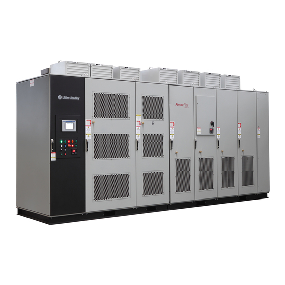
Allen-Bradley PowerFlex 6000 User Manual
Medium voltage variable frequency drive
Hide thumbs
Also See for PowerFlex 6000:
- Firmware, parameters, and troubleshooting manual (214 pages) ,
- User manual (146 pages) ,
- Installation instructions manual (66 pages)

Related Manuals for Allen-Bradley PowerFlex 6000


Summary of Contents for Allen-Bradley PowerFlex 6000
- Page 1 User Manual PowerFlex® 6000 Medium Voltage Variable Frequency Drive Publication 6000-UM001B-EN-P...
- Page 2 Arc Flash. Arc Flash will cause severe injury or death. Wear proper Personal Protective Equipment (PPE). Follow ALL Regulatory requirements for safe work practices and for Personal Protective Equipment (PPE). Allen-Bradley, Rockwell Software, Rockwell Automation, and TechConnect are trademarks of Rockwell Automation, Inc. Trademarks not belonging to Rockwell Automation are property of their respective companies.
-
Page 3: Table Of Contents
Table of Contents Preface Introduction............7 Who Should Use This Manual . - Page 4 Table of Contents Main Interface Controls ......... . 35 Set Frequency (Hz) .
- Page 5 Preventative Maintenance Schedule PowerFlex 6000 Maintenance Schedule ......123 Rockwell Automation Publication 6000-UM001B-EN-P - October 2014...
- Page 6 Table of Contents Appendix D Spare Parts Spare Parts List..........127 Appendix E Torque Requirements Torque Requirements .
-
Page 7: Introduction
What Is Not in This Manual This manual provides information specific to maintaining the PowerFlex 6000 medium voltage variable frequency drive. It does not include topics such as: • Dimensional and electrical drawings generated for each customer’s order •... -
Page 8: General Precautions
Service and Support Commissioning Support After installation, Rockwell Automation is responsible for commissioning activities for the PowerFlex 6000 product line. Contact your local Rockwell Automation sales representative to arrange commissioning. Rockwell Automation support includes, but is not limited to: • quoting and managing product on-site start-ups •... -
Page 9: Safety Considerations
Chapter Introduction Around the world, Allen-Bradley® PowerFlex® medium voltage drives from Rockwell Automation have built a reputation for providing efficient and reliable motor control for industry's most demanding applications. From the hardware designed to help optimize production to the power of networked control platforms, users can quickly and easily gain access to valuable information from their systems. -
Page 10: Environmental Conditions
Chapter 1 Introduction Refer to national and local safety guidelines for detailed procedures on how to safely isolate the equipment from hazards. ATTENTION: The national and local electrical codes outline provisions for safely installing and working on electrical equipment. Installation must comply with specifications regarding wire type, conductor sizes, branch circuit protection and disconnect devices. - Page 11 Introduction Chapter 1 A number of identical low voltage power modules are series-connected (cascaded) together to produce the medium voltage levels required to operate the motor. The voltage step for each module is relatively small and a Pulse Width Modulation (PWM) switching pattern is used so output harmonics and torque pulsations at the motor are minimal, even at lower speeds.
-
Page 12: Simplified Electrical Diagrams
Chapter 1 Introduction Simplified Electrical Figure 2 - 3000V / 3300V (18 Pulse - 9 Power Modules) Diagrams Isolation Transformer Secondary Windings Figure 3 - 6000V /6600V (36 Pulse - 18 Power Modules) Isolation Transformer Secondary Windings Figure 4 - 10,000V (54 Pulse - 27 Power Modules) Isolation Transformer Secondary Windings Rockwell Automation Publication 6000-UM001B-EN-P - October 2014... - Page 13 Introduction Chapter 1 Figure 5 - Connectivity Overview AC220V Control Power Reset Customer Input Contact MV Closed Start Stop MV Pre-Closed Permit Close MV MV Closed Indicator MV Closed Warning Indicator Warning Fault Indicator Fault Analog Output Current Running Indicator Running 4-20 mA Analog Output Frequency...
- Page 14 Chapter 1 Introduction Figure 6 - PowerFlex 6000 Principal Components Outgoing Load Cables Generous space for terminating incoming line cables. Generous space for terminating outgoing load cables. Integrally mounted Multi-pulse Isolation Transformer (3 wires in & 3 wires out) ensures...
-
Page 15: Standards Compliance
Introduction Chapter 1 Standards Compliance Technical specifications and relevant standards in the manufacture, testing, and acceptance of equipment include: Standard Number Standard Description IEEE 519 Electrical and Electronics Engineers Institute Harmonics Control Requirements IEC 60146 Semiconductor Converters–Specification of Basic Requirements IEC 60038:1983 IEC Standard Voltages IEC 60050-151:2001... - Page 16 Chapter 1 Introduction Standard Number Standard Description GB 10233.2005 Basic Test Method for Low Voltage Switchgear and Controlgear GB 12668.4-2006 Adjustable Speed Drive Electrical System, Part 4: General Requirement for Voltage up to 35 kV GB 12668.3-2006 Adjustable Speed Drive Electrical System, Part 3: EMC Requirement and Testing Method GB 12668.701-2013 Adjustable Speed Drive Electrical System, Part 701: Communication GB/T 15139-94...
-
Page 17: Elevation Drawings
Chapter Drive System Layout There are two basic power cell configurations offered in the PowerFlex 6000 ≤ product line. For a drive amperage rating 200 A, a fixed-mounted power module design is supplied. Fixed-mounted modules are shipped installed in the drive. For a drive amperage rating of >200 A, a drawout power module design is supplied. -
Page 18: Isolation Transformer Cabinet
Chapter 2 Drive System Layout Figure 8 - Drawout Power Module Drive Configuration Isolation Transformer Cabinet LV Control Cabinet Power Module Cabinet Isolation Transformer Cabinet Isolation Transformer Isolation Transformer Temperature Monitor Isolation Transformer Auxiliary Cooling Fans Top-mounted Main Cooling Fan(s) Incoming Line Power Cable Connections Outgoing Motor Cable Connections Door Position Limit Switch... - Page 19 Drive System Layout Chapter 2 Figure 9 - Isolation Transformer Cabinet (Fixed-mounted Power Module Drive Configuration) Top-mounted Main Cooling Fan(s) Outgoing Motor Power Cable Connections Door Position Incoming Line Power Limit Switches Cable Connections Isolation Transformer Voltage Sensing Board Power Cable Connections to Power Modules Cable Clamp Isolation Transformer...
-
Page 20: Isolation Transformer
Chapter 2 Drive System Layout Isolation Transformer The primary winding of the isolation transformer is rated for the voltage of the distribution system. It is connected to the distribution system by the incoming line power cables. The secondary windings of the isolation transformer are connected to the inputs of the power modules. -
Page 21: Isolation Transformer Temperature Monitor
Drive System Layout Chapter 2 For drives with fixed-mounted power modules, the U and W phase interconnections to the isolation transformer secondary windings are on the front of the isolation transformer and the connections to the V phase are on the rear of the isolation transformer. -
Page 22: Isolation Transformer Auxiliary Cooling Fans
Chapter 2 Drive System Layout Isolation Transformer Auxiliary Cooling Fans Six fans are mounted directly underneath the isolation transformer to force air directly through the windings - to ensure reliable cooling. A baffle structure surrounds the periphery of the transformer structure to ensure the cooling air does not bypass the interior of the transformer windings. -
Page 23: Door Position Limit Switch
Drive System Layout Chapter 2 Door Position Limit Switch Each cabinet door that allows access to medium voltage components is lockable and also has a Guardmaster® safety limit switch. If the cabinet door is opened when the input switching device feeding power to the drive is closed, the input device will be tripped off. -
Page 24: Voltage Sensing Board
Chapter 2 Drive System Layout Voltage Sensing Board The Voltage Sensing Board (VSB) is connected to the drive output terminals that connect to the motor. The VSB converts motor voltage to low voltage levels which allows the drive to monitor the output voltage to the motor. Figure 14 - Voltage Sensing Board Figure 15 - Power Cabling Overview (3.3 kV Fixed-mounted Power Module Configuration) Motor... -
Page 25: Power Module Cabinet
Drive System Layout Chapter 2 Power Module Cabinet Power Modules Hall Effect Current Sensors (HECs) Top-mounted Main Cooling Fan(s) Figure 16 - Fixed-mounted Power Module Configuration Figure 17 - Drawout Power Module Configuration Rockwell Automation Publication 6000-UM001B-EN-P - October 2014... -
Page 26: Power Modules
Chapter 2 Drive System Layout Power Modules Power Modules are available in a wide variety of amperage ratings relating to the required motor current. Power Modules rated up to and including 200 A are fixed-mounted in the drive and ship already installed. Drawout power modules are supplied for a drive current rating of >200 A. - Page 27 Drive System Layout Chapter 2 The status information of the Power Module is transmitted through the electrical-optical converter and sent to the main control unit. When there is a fault, the main control unit sends control signals to lockout or bypass the affected Power Module.
-
Page 28: Hall Effect Current Sensors (Hecs)
Chapter 2 Drive System Layout Table 1 - Power Module Ratings Catalog Number Spare Part Number Current Rating (Amps) TPUxx/030-AC3 HTPUXX/030-AC3-R TPUxx/040-AC3 HTPUXX/040-AC3-R TPUxx/050-AC3 HTPUXX/050-AC3-R TPUxx/060-AC3 HTPUXX/060-AC3-R TPUxx/075-AC3 HTPUXX/075-AC3-R TPUxx/080-AC3 HTPUXX/080-AC3-R TPUxx/100-AC3 HTPUXX/100-AC3-R TPUxx/120-AC3 HTPUXX/120-AC3-R TPUxx/150-AC3 HTPUXX/150-AC3-R TPUxx/180-AC3 HTPUXX/180-AC3-R TPUxx/200-AC3 HTPUXX/200-AC3-R TPUxx/300-AC3 HTPUXX/300-AC3-R... -
Page 29: Lv Control Cabinet
Drive System Layout Chapter 2 LV Control Cabinet Control Unit (all modules) The LV Control Cabinet consists of the Control Unit, the human-machine Interface (HMI), PLC, AC/DC power supplies, contactors and relays. The HMI is located on the front door of the LV Control Cabinet, where an operator can setup, monitor, and control the drive. -
Page 30: Control Unit (All Modules)
This includes controlling the power modules to produce the required output voltage and frequency, monitoring the power modules, motor voltage, and motor current to provide alarm and trip signals based on the information. Figure 20 - PowerFlex 6000 Interface Transceiver Fiber Optic Sockets... - Page 31 Drive System Layout Chapter 2 Figure 21 - Control Unit Layout RJ45 Modbus TCP/IP Fieldbus RS-485 Modbus HECS Communication Board CPU Board Modbus PWM Board A PWM Board B PWM Board C Phase B Phase A Phase C Power Modules Power Modules Power Modules Table 2 - Control Unit description...
-
Page 32: Plc
Drive in alarm state Reserved The PowerFlex 6000 uses a Micro850 PLC to perform many of its internal control functions. The PLC controls and monitors the cooling fans, input and bypass switching devices, door switch status, etc. The PLC is also responsible for interfacing with the user's automation control system via many optional communication protocols. -
Page 33: Overview
Chapter Setup and Operation Overview The structure of the touchscreen operation is shown in Figure Figure 23 - HMI Overview Main Interface Home Alarm Operation Settings Trends Data Display Main Operation Alarm Status Auto Manual User Setup Default R&D Bypass Bypass Bypass Set Frequency... -
Page 34: Drive Setup And Configuration Controls
Chapter 3 Setup and Operation Drive Setup and Configuration Controls There are five buttons in the Top Menu Bar. A description of the functionality is described in Table Table 3 - Setup and Configuration Controls • Return to Main Interface screen •... -
Page 35: Operation Bar
Setup and Operation Chapter 3 Operation Bar Table 5 - Operation Bar Buttons Start Starts the drive only if no fault is found during self test at startup; otherwise, this button is invalid Accel Increases the frequency by the set step Decel Decreases the frequency by the set step Stop... -
Page 36: Set Frequency (Hz)
Chapter 3 Setup and Operation Set Frequency (Hz) 1. Press the Set Frequency: input field. 2. Press the Set Freq: input field. Numpad Cancel Enter Backspace 3. Enter desired frequency and press 4. Press to accept or to cancel. Rockwell Automation Publication 6000-UM001B-EN-P - October 2014... -
Page 37: Drive Operation Controls
Setup and Operation Chapter 3 Drive Operation Controls Press the desired Drive Operation Control button, and to accept or to cancel. ATTENTION: Drive Operation Controls will only function if using Local Control, otherwise the following dialog appears. Rockwell Automation Publication 6000-UM001B-EN-P - October 2014... -
Page 38: View Version Information
Chapter 3 Setup and Operation View Version Information Press under Version Info. to view the currently installed Firmware. The Version Information screen shows the most current firmware installed for the applicable devices. Will always appear blue The number of Power Modules in the drive will appear as blue;... -
Page 39: Alarm
Setup and Operation Chapter 3 Alarm If the drive encounters and alarm or warnings, will blink, indicating an active alarm. Press the button in the Top Menu Bar to see the active alarms. List of Active Alarms Alarm Code Quantity Accumulated Time Alarm Code... -
Page 40: Alarm History
Chapter 3 Setup and Operation Alarm History Press to see a detailed listed of all warnings and faults on the drive. The controls to scroll through the alarms are the same. Sort Alarms Press once to sort once to sort by time. Press again to sort by message. Current alarms appear as red;... -
Page 41: Trends
Setup and Operation Chapter 3 Trends There are three different trending options, Voltage, Current, and Trends. Press any button to view the trends. You can view Voltage, Current, or Frequency trends. Voltage is measured in volts, Current in amps, and Frequency in Hz. Back Y-Axis X-axis... -
Page 42: View Voltage, Current Or Frequency Trends
Chapter 3 Setup and Operation View Voltage, Current or Frequency Trends 1. From the Main Interface screen, press 2. Press , or in the Trends Selection screen. 3. Use the buttons to zoom in or out. Press the buttons to scroll. The time shown in the X-axis captures 20 minutes. -
Page 43: Operation
Setup and Operation Chapter 3 Operation The Operation interface displays the bypass mode, control owner selection, and contactor operation. Select Local/ Remote Control Bypass Configuration Open/Close Drive/Bypass Contactors In this screen, you can: Confirm Bypass Mode Choose Local/Remote Operation Open/Close Drive Input and Output Contactors Open/Close Bypass Contactors Confirm Bypass Mode 1. - Page 44 Chapter 3 Setup and Operation Manual Bypass Cabinet Automatic Bypass Cabinet Note the Contactor Operation selection appears when Automatic Bypass is selected 3. To change the Bypass Mode: a. Press b. Press c. Choose desired Bypass Mode under Select Bypass Mode. d.
-
Page 45: Choose Local/Remote Operation
Setup and Operation Chapter 3 Choose Local/Remote Operation 1. Press from the Main Interface screen. 2. Under Control Owner Selection, press either 3. Select to confirm in the Select Local Control? or Select Remote Control? dialog box. ATTENTION: This operation can only operate while drive is not running. Rockwell Automation Publication 6000-UM001B-EN-P - October 2014... -
Page 46: Open/Close Drive Input And Output Contactors
Chapter 3 Setup and Operation Open/Close Drive Input and Output Contactors Turn the 3-position on the selector switch on the front of the LV Cabinet to the IMPORTANT Drive position. 1. Under Contactor Operation, press either 2. Select to confirm in the Close Drive Input & Output Contactors? or Open Drive Input &... -
Page 47: Open/Close Bypass Contactors
Setup and Operation Chapter 3 Open/Close Bypass Contactors Turn the 3-position on the selector switch on the front of the LV Cabinet to the IMPORTANT Bypass position. 1. Under Contactor Operation, press either 2. Select to confirm in the Close Bypass Contactors? or Open Bypass Contactors? dialog box. -
Page 48: Settings
Chapter 3 Setup and Operation Settings The Settings screen is where you can access and modify parameters, choose or change system language, or change bypass mode. Current Access Level User Account System Settings Select Language and Bypass Mode User Settings View or modify User-level parameter settings Setup Settings View or modify “P”... - Page 49 Setup and Operation Chapter 3 3. Select bypass mode and press to accept or to cancel. 4. Press to accept. ATTENTION: Operations in this graphic can only operate while on local control. ATTENTION: This operation can only be performed when any switch is closed. Rockwell Automation Publication 6000-UM001B-EN-P - October 2014...
-
Page 50: User Settings
Chapter 3 Setup and Operation User Settings You can access, view, or change the user parameters in User Settings. Reset all Parameters to Factory Values User Parameter List User Parameter Value Parameter Description Change User Parameters 1. Press 2. The User Login dialog box appears. Press 3. - Page 51 Setup and Operation Chapter 3 4. Press to login. 5. If the login was successful, the Current User will show as User. 6. Press IMPORTANT If the login information was incorrect, you will be prompted to login again. In the User Parameters Settings screen, the user parameters automatically refresh.
- Page 52 Chapter 3 Setup and Operation Press to restore all user parameters to the factory setting. ATTENTION: Operations in this graphic can only operate while on local control. ATTENTION: This operation can only operate while drive is not running. Press to return to the Parameter Access Level screen. User parameter access will logout when you exit User Settings.
-
Page 53: Setup Settings
Setup and Operation Chapter 3 Setup Settings View or modify “P” or “T” Parameters in the Setup Settings interface. Reset Parameter Values Parameter Number Page Up Parameter Field Page Down Select a Parameter number to see the description here View/Change P or T Parameters IMPORTANT You must have Setup login access to view or modify “P”... - Page 54 Chapter 3 Setup and Operation Press to enter user details. Press when finished. Press to enter password details. Press when finished. 3. Press to login. The Current User will now display Setup, indicating appropriate access has been granted. 4. Once logged in, press to proceed.
-
Page 55: Restore "P" Or "T" Parameters
Setup and Operation Chapter 3 Restore “P” or “T” Parameters Press to restore the parameters to factory settings. Press to accept or to cancel. ATTENTION: Operations in this graphic can only operate while on local control. ATTENTION: This operation can only operate while drive is not running. Rockwell Automation Publication 6000-UM001B-EN-P - October 2014... - Page 56 Chapter 3 Setup and Operation Notes: Rockwell Automation Publication 6000-UM001B-EN-P - October 2014...
-
Page 57: P Parameters
Chapter Parameters and Function Codes P Parameters Parameter Description Default Modify Lower Upper Number Value Root Limit Limit P004 Command Source 0: Communication Port 1: Other Sources P005 Restore Factory Settings 40: User Level 30: Setup Level 50: R&D Level P007 Number Of Power Cells Per Phase P008... - Page 58 Chapter 4 Parameters and Function Codes Parameter Description Default Modify Lower Upper Number Value Root Limit Limit P090 Skip Frequency 1 Lower Limit P091 Skip Frequency 1 Upper Limit P092 Skip Frequency 2 Lower Limit P093 Skip Frequency 2 Upper Limit P113 Flying Start-Initial Output Voltage Percentage (%) P114...
- Page 59 Parameters and Function Codes Chapter 4 Parameter Description Default Modify Lower Upper Number Value Root Limit Limit P232 Filter Time For Overspeed Fault (Lower Limit) 32767 P233 Threshold Of Over-Speed Fault At Lower Frequency Limit 20 199.99 P234 Threshold Of Over-Speed Fault At Upper Frequency Limit 20 199.99 P235 Frequency Deviation Warning Cancellation Threshold...
- Page 60 Chapter 4 Parameters and Function Codes Parameter Description Default Modify Lower Upper Number Value Root Limit Limit P313 Digital Output #3 Logic 1: Inverting 0: Non-Inverting P314 Digital Output #3 Bit Selection (0...15) P315 Digital Output #3 Delay (ms) 32767 P316 Digital Output #4 Memory Address P317...
- Page 61 Parameters and Function Codes Chapter 4 Parameter Description Default Modify Lower Upper Number Value Root Limit Limit P346 Analog Output #4 Offset -100 P347 Analog Output #4 Scaling Factor 199.99 P351 Rated Frequency HMI Display Filter Time (ms) 32767 P352 Rated Frequency HMI Display Integer Part P353 Rated Frequency HMI Display Decimal Part...
- Page 62 Chapter 4 Parameters and Function Codes Parameter Description Default Modify Lower Upper Number Value Root Limit Limit P443 Upper Limit Of Current Compensation Input Deadband -16384 32767 P444 Lower Limit Of Current Compensation Input Deadband -16384 32767 P445 Proportional Coefficient Of Current Compensation (%) 199.99 P446 Integral Coefficient Of Current Compensation (ms)
-
Page 63: T Parameters
Parameters and Function Codes Chapter 4 T Parameters Parameter Description Default Modify Lower Upper Number Value Root Limit Limit Fault-To-Bypass 0: Disable 1: Enable Fault-To-Bypass Delay Fault-To-Bypass Delay When Starting the Motor (0...60s) Fault-To-Bypass Minimum Frequency Rated Frequency 0...Rated Frequency (Hz) Auto Restart After Input Supply Power Loss 0: Disable 1: Enable... -
Page 64: Alarm List
Chapter 4 Parameters and Function Codes Alarm List Code Alarm F0000 IGBT Set #1 Over Current In Power Cell #1 F0001 IGBT Set #2 Over Current In Power Cell #1 F0002 Input Over Voltage In Power Cell #1 F0004 Communication Error In Power Cell #1 F0005 No PWM1 Pulse For IGBT Set #1 In Power Cell #1 F0006... - Page 65 Parameters and Function Codes Chapter 4 Code Alarm F0300 IGBT Set #1 Over Current In Power Cell #4 F0301 IGBT Set #2 Over Current In Power Cell #4 F0302 Input Over Voltage In Power Cell #4 F0304 Communication Error In Power Cell #4 F0305 No PWM1 Pulse For IGBT Set #1 In Power Cell #4 F0306...
- Page 66 Chapter 4 Parameters and Function Codes Code Alarm F0601 IGBT Set #2 Over Current In Power Cell #7 F0602 Input Over Voltage In Power Cell #7 F0604 Communication Error In Power Cell #7 F0605 No PWM1 Pulse For IGBT Set #1 In Power Cell #7 F0606 No PWM2 Pulse For IGBT Set #2 In Power Cell #7 F0607...
- Page 67 Parameters and Function Codes Chapter 4 Code Alarm F0902 Input Over Voltage In Power Cell #10 F0904 Communication Error In Power Cell #10 F0905 No PWM1 Pulse For IGBT Set #1 In Power Cell #10 F0906 No PWM2 Pulse For IGBT Set #2 In Power Cell #10 F0907 IGBT Set #1 Failed To Turn On In Power Cell #10 F0908...
- Page 68 Chapter 4 Parameters and Function Codes Code Alarm F1204 Communication Error In Power Cell #13 F1205 No PWM1 Pulse For IGBT Set #1 In Power Cell #13 F1206 No PWM2 Pulse For IGBT Set #2 In Power Cell #13 F1207 IGBT Set #1 Failed To Turn On In Power Cell #13 F1208 IGBT Set #2 Failed To Turn On In Power Cell #13...
- Page 69 Parameters and Function Codes Chapter 4 Code Alarm F1505 No PWM1 Pulse For IGBT Set #1 In Power Cell #16 F1506 No PWM2 Pulse For IGBT Set #2 In Power Cell #16 F1507 IGBT Set #1 Failed To Turn On In Power Cell #16 F1508 IGBT Set #2 Failed To Turn On In Power Cell #16 F1509...
- Page 70 Chapter 4 Parameters and Function Codes Code Alarm F1806 No PWM2 Pulse For IGBT Set #2 In Power Cell #19 F1807 IGBT Set #1 Failed To Turn On In Power Cell #19 F1808 IGBT Set #2 Failed To Turn On In Power Cell #19 F1809 Power Cell #19 Bypassed F1810...
- Page 71 Parameters and Function Codes Chapter 4 Code Alarm F2107 IGBT Set #1 Failed To Turn On In Power Cell #22 F2108 IGBT Set #2 Failed To Turn On In Power Cell #22 F2109 Power Cell #22 Bypassed F2110 Over Temperature In Power Cell #22 F2111 Power Cell #22 Failed To Bypass F2112...
- Page 72 Chapter 4 Parameters and Function Codes Code Alarm F2408 IGBT Set #2 Failed To Turn On In Power Cell #25 F2409 Power Cell #25 Bypassed F2410 Over Temperature In Power Cell #25 F2411 Power Cell #25 Failed To Bypass F2412 One Phase Lost In Power Cell #25 F2413 Two Phases Lost In Power Cell #25...
- Page 73 Parameters and Function Codes Chapter 4 Code Alarm F2900 Cabinet Door Opened While Drive Energized F2901 E-Stop Trip F2902 Input Circuit Breaker Opened (Not Initiated By The Drive) F2903 Non-Zero Frequency Command Exists Upon Start F2904 Flying Start Failed F2905 Input Circuit Breaker Tripped F2909 System Locked...
- Page 74 Chapter 4 Parameters and Function Codes Code Alarm F3207 PWMB Board Not Compatible With PUB8 Board F3208 PWMB Board Not Compatible With PUB9 Board F3209 PWMB Board Not Compatible With PUB10 Board F3210 PWMB Board Not Compatible With PUB11 Board F3211 PWMB Board Not Compatible With PUB12 Board F3212...
- Page 75 Parameters and Function Codes Chapter 4 Code Alarm W0414 Input Over Voltage In Power Cell #5 Warning W0503 DC Bus Under Voltage In Power Cell #6 Warning W0514 Input Over Voltage In Power Cell #6 Warning W0603 DC Bus Under Voltage In Power Cell #7 Warning W0614 Input Over Voltage In Power Cell #7 Warning W0703...
- Page 76 Chapter 4 Parameters and Function Codes Code Alarm W2414 Input Over Voltage In Power Cell #25 Warning W2503 DC Bus Under Voltage In Power Cell #26 Warning W2514 Input Over Voltage In Power Cell #26 Warning W2603 DC Bus Under Voltage In Power Cell #27 Warning W2614 Input Over Voltage In Power Cell #27 Warning W2800...
-
Page 77: Safety
Chapter Preventative Maintenance and Component Replacement Safety ATTENTION: Servicing energized Medium Voltage Motor Control Equipment can be hazardous. Severe injury or death can result from electrical shock, bump, or unintended actuation of controlled equipment. Recommended practice is to disconnect and lockout control equipment from power sources, and release stored energy, if present.For countries following NEMA standards, refer to National Fire Protection Association Standard No. -
Page 78: Daily Inspection
Chapter 5 Preventative Maintenance and Component Replacement Daily Inspection Check the following items during normal operation of the drive: • abnormal noise or vibration in the drive or motor • abnormal temperature in the drive or motor • ambient temperature in the control room above nominal •... -
Page 79: Physical Checks (No Medium Voltage Or Control Power)
Physical Checks (No Medium Power Connection Inspection Voltage or Control Power) • Inspect PowerFlex 6000 drive, input/output/bypass sections, and all associated drive components for loose power cable connections and ground cable connections: torque them based on the required torque specifications. -
Page 80: Medium Voltage Testing
Chapter 5 Preventative Maintenance and Component Replacement Medium Voltage Testing Medium voltage insulation resistance (IR) or dielectric withstanding voltage (megger) tests should not be used to check solid-state control equipment. When meggering electrical equipment, such as transformers or motors, solid-state devices must be bypassed before performing the test. -
Page 81: Isolation Transformer Cabinet
Preventative Maintenance and Component Replacement Chapter 5 Isolation Transformer Cabinet Replace/Clean Door Mounted Air Filters Inspect Top Mounted Main Cooling Fans Replace Top Mounted Main Cooling Fans Fan Balance Inspect Isolation Transformer Auxiliary Cooling Fans Replace Isolation Transformer Auxiliary Cooling Fans Inspect Isolation Transformer Inspect Voltage Sensing Board Replace Voltage Sensing Board... -
Page 82: Inspect Top Mounted Main Cooling Fans
Chapter 5 Preventative Maintenance and Component Replacement Use only Rockwell Automation-supplied or -approved replacement filters (see Spare Parts List on page 127). Replace the filters in the reverse order of its removal. Check that there are no openings to allow foreign matter to enter the drive. -
Page 83: Replace Top Mounted Main Cooling Fans
Preventative Maintenance and Component Replacement Chapter 5 Replace Top Mounted Main Cooling Fans The top fan housing consists of a motor and impeller assembly. To replace the fan, it is necessary to remove the Fan Housing Lid. ATTENTION: Fan replacement requires working at a significant height from the floor. -
Page 84: Fan Balance
Chapter 5 Preventative Maintenance and Component Replacement 3. Remove and retain four M6 x 12 bolts from the top of the Fan Support Bracket, and remove the bracket from the Fan Assembly. 4. Remove the Wiring Cover and disconnect the wiring. 5. -
Page 85: Inspect Isolation Transformer Auxiliary Cooling Fans
Preventative Maintenance and Component Replacement Chapter 5 Inspect Isolation Transformer Auxiliary Cooling Fans When the drive is running, verify that each of the coil temperatures are the same on the Isolation Transformer Temperature Monitor display. If there is more than a 5 °C difference between the highest and lowest temperature, check the Isolation Transformer Auxiliary Cooling Fans. -
Page 86: Replace Isolation Transformer Auxiliary Cooling Fans
Chapter 5 Preventative Maintenance and Component Replacement Replace Isolation Transformer Auxiliary Cooling Fans 1. If the fan is in the front, cut the tie straps to loosen the wire bundle from the top of the fan. 2. Disconnect three wires at the top of the fan. 3. -
Page 87: Inspect Voltage Sensing Board
Preventative Maintenance and Component Replacement Chapter 5 Inspect Voltage Sensing Board The input VSB cable connections and output VSB wire connectors must be firmly fastened and show no signs of damage or accumulation of dirt, dust, or debris. Replace Voltage Sensing Board ATTENTION: To prevent electrical shock, disconnect the main power before working on the Voltage Sensing Board. -
Page 88: Inspect Door Position Limit Switch
Chapter 5 Preventative Maintenance and Component Replacement 3. Remove the nylon nuts which connect the Voltage Sensing Board to the Insulation Board. Figure 28 - Remove the Voltage Sensing Board from the Insulation Board Nylon M10 Nut (x9) Nylon M10 Nut (x9) Insulation Board Voltage Sensing Board 4. -
Page 89: Replace Door Position Limit Switch
Preventative Maintenance and Component Replacement Chapter 5 Replace Door Position Limit Switch ATTENTION: Ensure the input circuit breaker feeding the drive is open. Lock out and tagout the input circuit breaker before performing any work on the drive or bypass units. 1. -
Page 90: Power Module Cabinet
Chapter 5 Preventative Maintenance and Component Replacement Power Module Cabinet Inspect, Clean, or Replace Door Mounted Air Filters Inspect or Replace Top Mounted Main Cooling Fans Inspect Power Modules Replace Power Module Install Drawout Power Modules Replace Power Module Fuses Inspect or Replace HECS Inspect or Replace Door Position Limit Switch Inspect, Clean, or Replace Door Mounted Air Filters... -
Page 91: Replace Power Module
Preventative Maintenance and Component Replacement Chapter 5 Replace Power Module Table 7 - Power Module Specifications Type Output Rating (Amps) Dimensions (HxWxD), approx. Weight, approx. ≤150 A Fixed-mounted 420 x 180 x 615 mm (16.5 x 7.1 x 24.2 in.) 20 kg (44.1 lb) 151...200 A 420 x 260 x 615 mm (16.5 x 10.2 x 24.2 in.) - Page 92 Chapter 5 Preventative Maintenance and Component Replacement 3. Remove the Output Copper Bars that connect adjacent Power Modules (Figure 31). If the Power Module is at the end of a row, remove the VSB and Motor cable instead of an output copper bus. 4.
- Page 93 Preventative Maintenance and Component Replacement Chapter 5 Replace Drawout Power Module ATTENTION: Only authorized personnel should operate the lift cart. Keep hands and feet away from the lifting mechanism. Do not stand under the lift tray when in use. Store the lift cart with the tray fully lowered. Lift Carts are supplied and shipped separately with drawout power module configurations.
- Page 94 Chapter 5 Preventative Maintenance and Component Replacement Figure 33 - Drawout Power Module Lifting Handles Mounting Rail Finger Assemblies Recessed Lifting Handles ATTENTION: Do not use the front mounted positioning handles for lifting the Power Modules. They are designed to position or withdraw the Power Module when on the tray assembly.
-
Page 95: Install Drawout Power Modules
Preventative Maintenance and Component Replacement Chapter 5 Install Drawout Power Modules 1. Place the Power Module module on the lift cart. Ensure the Power Module is properly oriented; the finger assemblies must face towards the drive. 2. Position the lift cart in front of the cabinet and raise the Power Module to the proper height. - Page 96 Chapter 5 Preventative Maintenance and Component Replacement 5. Insert the locking key into the cam mechanism actuator and rotate clockwise while gently pushing on the face of the Power Module. Cabinet Finger Stab Assemblies Assemblies Connection to Motor Phase Bus Three Phase Cam Mechanism Input Power...
-
Page 97: Replace Power Module Fuses
Preventative Maintenance and Component Replacement Chapter 5 Replace Power Module Fuses Fixed-mounted Power Module ATTENTION: Ensure the input circuit breaker feeding the drive is open. Lock out and tagout the input circuit breaker before performing any work on the drive or bypass units. - Page 98 Chapter 5 Preventative Maintenance and Component Replacement Drawout Power Module ATTENTION: Ensure the input circuit breaker feeding the drive is open. Lock out and tagout the input circuit breaker before performing any work on the drive or bypass units. 1. Remove and retain the M12 bolt, washer, lock washer, and nut from the top and bottom of the fuse.
-
Page 99: Inspect Or Replace Hecs
Preventative Maintenance and Component Replacement Chapter 5 Inspect or Replace HECS ATTENTION: To prevent electrical shock, disconnect the main power before working on the drive. Verify that all circuits are voltage-free, using a hot stick or appropriate high voltage-measuring device. Failure to do so may result in injury or death. -
Page 100: Inspect Or Replace Door Position Limit Switch
Chapter 5 Preventative Maintenance and Component Replacement 4. Remove and retain M5 x 12 hardware connecting the HECS to the Mounting Bracket. Note the orientation of the HECS on the bracket. The new HECS must be IMPORTANT installed facing the same direction. Figure 36 - Exploded view of the HECS and Mounting Bracket M5 x 12 Nut Washer... -
Page 101: Lv Control Cabinet
Preventative Maintenance and Component Replacement Chapter 5 LV Control Cabinet Inspect AC/DC Power Supplies Replace AC/DC Power Supplies Inspect UPS Replace UPS Replace UPS Batteries Inspect PLC Inspect/Replace Control Unit or Control Boards Inspect the HMI Replace the HMI Replace LV Control Relays Replace LV Control Circuit Breakers Inspect Coils Inspect Contacts... -
Page 102: Replace Ac/Dc Power Supplies
Chapter 5 Preventative Maintenance and Component Replacement Replace AC/DC Power Supplies ATTENTION: Always perform Power Lockout procedure before servicing equipment. Verify with a hot stick or appropriate voltage measuring device that all circuits are voltage free. Failure to do so may result in severe burns, injury, or death. - Page 103 Preventative Maintenance and Component Replacement Chapter 5 G3 Power Supply 1. Loosen, but do not remove, the screws on the top of the G3 Power Supply. 2. Remove the wires. Figure 40 - Remove G3 Power Supply wires (G1 and G2 Power Supply not shown for clarity) Loosen screws and remove all wires 3.
-
Page 104: Inspect Ups
Chapter 5 Preventative Maintenance and Component Replacement Inspect UPS 1. Check there are no obstructions or dirt/debris in the exhaust heat fan. 2. Ensure there are no visible signs of damage. If the drive has not been turned on for more than 3 months, the UPS batteries IMPORTANT must be charged for at least 10 hours. -
Page 105: Replace Ups
Preventative Maintenance and Component Replacement Chapter 5 Replace UPS ATTENTION: Always perform Power Lockout procedure before servicing equipment. Verify with a hot stick or appropriate voltage measuring device that all circuits are voltage free. Failure to do so may result in severe burns, injury, or death. -
Page 106: Replace Ups Batteries
Chapter 5 Preventative Maintenance and Component Replacement 6. Install the replacement UPS, and reconnect input and output cables. 7. Turn the Q1 circuit break and press the ON button on the UPS. Wait for 2...3 seconds. 8. Using a voltmeter, check the input voltage on the line side of the Q2 circuit breaker. - Page 107 Preventative Maintenance and Component Replacement Chapter 5 3. Remove the cables from the top battery one at a time, and immediately wrap insulating tape around end of each cable. Indicate on the tape the positive or negative terminal, as appropriate. ATTENTION: Do not touch the positive and negative battery wires to each other or the UPS enclosure.
-
Page 108: Inspect Plc
Chapter 5 Preventative Maintenance and Component Replacement Inspect PLC 1. Verify all input and output terminal connections are secure. 2. Verify all LEDs are working and indicate normal status. See publication 2080-UM002_-EN-P for further information for the PLC, or publication 2080-WD002_-EN-P for further information regarding the Isolated Serial Port Plug-in Modules. - Page 109 Preventative Maintenance and Component Replacement Chapter 5 Figure 46 - Remove Retaining Screws of Control Unit Washer Lock washer M6 x 12 Bolt 6. Install the new Control Unit in reverse order of removal. Refer to Electrical Drawings for exact placement of all wires and connections. Replace a Control Board ATTENTION: Some circuit boards can be destroyed by static charges.
- Page 110 Chapter 5 Preventative Maintenance and Component Replacement 3. Use both hands and carefully remove the board by using the handles on either side on the front of the board. Only remove the board using the two handles on the front 4.
-
Page 111: Inspect The Hmi
Preventative Maintenance and Component Replacement Chapter 5 5. Refer to the Electrical Drawings for reconnecting the fiber optic wires. Connect Fiber Optic Wires here (Refer to Electrical Drawings) Reconnect the HMI Communication Cable Reconnect the bottom terminal Inspect the HMI 1. - Page 112 Chapter 5 Preventative Maintenance and Component Replacement 1. Disconnect the data cable from communication board, the EtherNet/IP cable from PLC, the ground cable, and the 24V power supply cable. 24V Power Supply Data Cable from Communication Board EtherNet/IP Cable from PLC Ground Cable 2.
-
Page 113: Replace Lv Control Relays
Preventative Maintenance and Component Replacement Chapter 5 Replace LV Control Relays ATTENTION: Always perform Power Lockout procedure before servicing equipment. Verify with a hot stick or appropriate voltage measuring device that all circuits are voltage free. Failure to do so may result in severe burns, injury, or death. -
Page 114: Replace Lv Control Circuit Breakers
Chapter 5 Preventative Maintenance and Component Replacement 3. Release the spring-loaded latches at the bottom of the control relay and lift the control relay off the DIN rail. Figure 49 - Release the spring-loaded latch on the LV Control Relay 4. - Page 115 Preventative Maintenance and Component Replacement Chapter 5 3. Loosen the top and bottom screws and remove the wires on the circuit breaker. Figure 51 - Screw location on Circuit Breaker Loosen screws and remove wires Circuit Breaker Switch must be in the Off position Loosen screws and remove wires 4.
-
Page 116: Inspect Coils
Do not use solvents on printed circuit boards. Inspect Locking and Interlocking Devices Check these devices to verify proper working condition. Make any necessary replacements only with Allen-Bradley renewal parts or kits. Adjust or repair only in accordance with Allen-Bradley instructions found in the product User Manuals. -
Page 117: Connections
Preventative Maintenance and Component Replacement Chapter 5 Connections Inspect LV Component Terminal and Plug-in Connections Inspect Medium Voltage Cable Connections Inspect Power Cable and Control Wire Terminals Inspect Transformer Secondary Windings Inspect Power Module Input and Output Power Connections Inspect LV Component Terminal and Plug-in Connections All LV control connections must be secure. -
Page 118: Inspect Power Module Input And Output Power Connections
Chapter 5 Preventative Maintenance and Component Replacement Inspect the bus bars and cable connections. Check for any signs of overheating / discoloration and tighten the bus connections to the required torque specifications. Clean all cables and bus bars that exhibit dust build-up. Check for corrosion, excessive temperature, or contamination. -
Page 119: Technical Specifications
Appendix Technical Specifications Description Power Rating Range @ 3 kV motor voltage 320…1600 kW Power Rating Range @ 3.3 kV motor voltage 360…1720 kW Power Rating Range @ 6 kV motor voltage 200…3360 kW Power Rating Range @ 6.6 kV motor voltage 220…3720 kW Power Rating Range @ 10 kV motor voltage 200…5600 kW... - Page 120 Appendix A Technical Specifications Notes: Rockwell Automation Publication 6000-UM001B-EN-P - October 2014...
-
Page 121: Catalog Number Explanation
(4) A A A Drive Current Ratings shown are only for Normal Duty, 0...1000 m altitude, and 0...40 ºC ambient temperature. 16 Amp 26 Amp Not all drive current ratings are available in all voltages. Refer to the PowerFlex 6000 Selection Guide. 18 Amp 28 Amp... - Page 122 NOT available as a load voltage. For 11 kV line voltage, the only valid load voltage options 50 Hz are 3.3 kV and 6.6 kV. 60 Hz Options Refer to PowerFlex 6000 Medium Voltage Drives Options List. Rockwell Automation Publication 6000-UM001B-EN-P - October 2014...
-
Page 123: Preventative Maintenance Schedule
Appendix Preventative Maintenance Schedule PowerFlex 6000 This Annual Preventative Maintenance Program includes a visual inspection of all drive components visible from the front of the unit, power supply voltage level Maintenance Schedule checks, general cleaning and maintenance, checking of all accessible power connections for tightness, and other tasks. - Page 124 Appendix C Preventative Maintenance Schedule Table 8 - Preventative Maintenance Schedule (0...10 yrs.) Interval Period (in years from commissioning date) Component Component Component/Item Location Category Isolation Air-cooling system Door Mounted Air Filters C / R C / R C / R C / R C / R C / R...
- Page 125 Preventative Maintenance Schedule Appendix C Table 9 - Preventative Maintenance Schedule (11...20 yrs.) Interval Period (in years from commissioning date) Component Component Component/Item Location Category Isolation Air-cooling system Door Mounted Air Filters C / R C / R C / R C / R C / R C / R...
- Page 126 Appendix C Preventative Maintenance Schedule Notes: Rockwell Automation Publication 6000-UM001B-EN-P - October 2014...
- Page 127 Appendix Spare Parts Spare Parts List Part Number Part Description Repair Replace H5JZ-065-276-R Power Module Control Board 315 H5JZ-065-269-R DB Board, Ver. 1.0.0 H5JZ-065-271-01-R Control Unit Digital Signal Processor Board (H5JZ-065-271-01) H5JZ-065-270-R Control Unit Analog Signal Processor Board (Version 1.0.0) ...
- Page 128 Appendix D Spare Parts Part Number Part Description Repair Replace H01220097-R UPS KR1000 1000VAH-AC220V I/O H01200077-R Hall Effect Current Sensor CHF (100G 100A-15V-5V-D35) H01200078-R Hall Effect Current Sensor CHF (200G 200A-15V-5V-D35) H01200079-R Hall Effect Current Sensor CHF (300G 300A-15V-5V-D35) ...
- Page 129 Appendix Torque Requirements Torque Requirements Proper tightening torque must be used for installation and wiring. Table 10 - Torque Requirements Torque Thread Size N•m lb•ft 16.2 28.8 45.7 70.1 135.7 Rockwell Automation Publication 6000-UM001B-EN-P - October 2014...
- Page 130 Appendix E Torque Requirements Notes: Rockwell Automation Publication 6000-UM001B-EN-P - October 2014...
- Page 131 Index AC/DC Power Supplies 101 Catalog Number Explanation 121 Check Output Voltage 101 Close Bypass Contactor 47 Inspect 101 Close Drive Input Contactors 46 Maintenance Schedule 124 Close Drive Output Contactors 46 Replace 102 Code 39 Replace G1 102 Coils Replace G2 102 Replace G3 103 Maintenance 116...
- Page 132 Index Drawout Power Module Fuse Catalog Number 28 Drawout Power Module Fuse Hardware 98 Configuration 25 Fixed-Mounted Power Module Fuse Hardware Dimensions 91 Lift Cart 93 Replace Drawout Power Module 98 Locking Key 96 Replace Fixed-mounted Power Module 97 Low Voltage Power Module 26 Output Rating 91 Replace 93 Replace Fuse 98...
- Page 133 Index Isolation Transformer 24V Power Supply 112 3-phase Primary Coils 20 Acc Time 39 Auxiliary Cooling Fans 22 Additional Information 112 Clean/Replace Air Filters 81 Alarm 34 Fan Balance 84 Alarm History 40 Inspect 86 Alarm Status 39 Inspect Secondary Windings 117 Change Interface Language 48 Location 19 Change P Parameters 53...
- Page 134 Index LV Control Cabinet 29 AC/DC Power Supplies 101 Nominal Line Voltage 122 Component Layout 29 Nominal Load (Motor) Voltage 122 HMI Firmware 118 Inspect PLC 108 LV Control Circuit Breakers Hardware 115 LV Control Relay Hardware 113 Replace AC/DC Power Supplies 102 Open Bypass Contactor 47 Replace Control Boards 108 Open Drive Input Contactors 46...
- Page 135 Index PowerFlex 6000 Setup Settings Altitude Rating 121 Change P Parameters 53 Ambient Temperature Code 121 Change T Parameters 53 Bulletin Number 121 Function 48 Catalog Number Explanation 121 P Parameters 53 Drive Current Rating 121 T Parameters 53 Elevation Drawings 17...
- Page 136 Index Voltage Sensing Board 19 Hardware 88 T Parameters Inspect 87 List 63 Insulation Board 87 Restore 55 Location (Drawout Power Module Technical Specifications 119 Configuration) 19 Temperature Monitor 21 Location (Fixed-mounted Configuration) 19 Maintenance Schedule 124 Layout 21 Power Cabling Overview 24 User Manual 21 Replace 87 Top Mounted Main Cooling Fan...
- Page 138 Medium Voltage Products, 135 Dundas Street, Cambridge, ON, N1R 5X1 Canada, Tel: (1) 519.740.4100, Fax: (1) 519.623.8930 Online: www.ab.com/mvb Allen-Bradley, Rockwell Software, Rockwell Automation, and TechConnect are trademarks of Rockwell Automation, Inc. Trademarks not belonging to Rockwell Automation are property of their respective companies.