ABB ACH580-31 Hardware Manual
Industrial drives
Hide thumbs
Also See for ACH580-31:
- Hardware manual (254 pages) ,
- Quick installation manual (33 pages) ,
- Installation manual (238 pages)
Table of Contents
Quick Links
Table of Contents

Related Manuals for ABB ACH580-31


Summary of Contents for ABB ACH580-31
- Page 1 — ABB INDUSTRIAL DRIVES ACH580-31 drives Hardware manual...
- Page 3 ACH580-31 drives Hardware manual Table of contents 1. Safety instructions 4. Mechanical installation 6. Electrical installation – IEC 10. Start-up 3AXD50000037066 Rev F Original instructions EFFECTIVE: 2022-10-14...
-
Page 5: Table Of Contents
Table of contents 5 Table of contents 1 Safety instructions Contents of this chapter ..................Use of warnings and notes ..................General safety in installation, start-up and maintenance ........ Electrical safety in installation, start-up and maintenance ......Electrical safety precautions ................Additional instructions and notes .............. - Page 6 Availability of d u /d t filter and common mode filter by drive type ......................Additional requirements for explosion-safe (EX) motors .... Additional requirements for ABB motors of types other than M2_, M3_, M4_, HX_ and AM_ ............... Additional requirements for braking applications ......
- Page 7 Table of contents 7 Additional requirements for the regenerative and low harmonics drives ....................... Additional requirements for ABB high-output and IP23 motors .. Additional requirements for non-ABB high-output and IP23 motors ..................... Additional data for calculating the rise time and the peak line-to-line voltage ................
- Page 8 8 Table of contents Implementing a motor temperature sensor connection ......... Connecting a motor temperature sensor to the drive through an option module ......................... Protecting the drive against ground faults ............Residual current device compatibility ............Implementing the emergency stop function ............Implementing the Safe torque off function ............
- Page 9 Table of contents 9 Connecting the power cables ................Connection diagram ..................Connection procedure ..................R8 power cable connection if you detach the cable connectors .. Connecting the control cables ................Connection diagram ..................Connection procedure ..................Installing option modules ..................Option slot 2 (I/O extension modules) ............
- Page 10 10 Table of contents DI5 as frequency input ..................DI6 as PTC input ....................AI1 and AI2 as Pt100, Pt1000, Ni1000, KTY83 and KTY84 sensor inputs (X1) ........................Safe torque off (X4) ..................Technical data ......................9 Installation checklist Contents of this chapter ..................Checklist ........................
- Page 11 Calculating the short-circuit current of the installation ......Calculation example ................Fuses (UL) ........................Circuit breakers (IEC) ....................ABB miniature and molded case circuit breakers ........Circuit breakers (UL) ....................Dimensions, weights and free space requirements .......... Free space requirements .................
- Page 12 Compliance with the European Machinery Directive and the UK Supply of Machinery (Safety) Regulations ..............Wiring .......................... Connection principle ..................Single ACH580-31 drive, internal power supply ......Single ACH580-31 drive, external power supply ......Wiring examples ....................Single ACH580-31 drive, internal power supply ......
- Page 13 Table of contents 13 Activation switch ....................Cable types and lengths .................. Grounding of protective shields ..............Operation principle ....................Start-up including validation test ................. Competence ....................... Validation test reports ..................Validation test procedure ................Use ..........................Maintenance ......................Competence ....................... Fault tracing ......................
- Page 14 14 Table of contents d u /d t filters ....................... When is a d u /d t filter needed? ............... d u /d t filter types ....................Description, installation and technical data of the filters .... Sine filters ........................17 CAIO-01 bipolar analog I/O adapter module Contents of this chapter ..................
- Page 15 Table of contents 15 19 CMOD-01 multifunction extension module (external 24 V AC/DC and digital I/O) Contents of this chapter ..................Product overview ...................... Layout and example connections ................. Mechanical installation .................... Necessary tools ....................Unpacking and examining the delivery ............Installing the module ..................
-
Page 17: Safety Instructions
Safety instructions 17 Safety instructions Contents of this chapter This chapter contains the safety instructions which you must obey when you install, start-up, operate and do maintenance work on the drive. If you ignore the safety instructions, injury, death or damage can occur. Use of warnings and notes Warnings tell you about conditions which can cause injury or death, or damage to the equipment. -
Page 18: General Safety In Installation, Start-Up And Maintenance
18 Safety instructions General safety in installation, start-up and maintenance These instructions are for all personnel who do work on the drive. WARNING! Obey these instructions. If you ignore them, injury or death, or damage to the equipment can occur. •... - Page 19 Safety instructions 19 • Before you adjust the drive operation limits, make sure that the motor and all driven equipment can operate throughout the set operation limits. • Before you activate the automatic fault reset or automatic restart functions of the drive control program, make sure that no dangerous situations can occur.
-
Page 20: Electrical Safety In Installation, Start-Up And Maintenance
20 Safety instructions Electrical safety in installation, start-up and maintenance ■ Electrical safety precautions These electrical safety precautions are for all personnel who do work on the drive, motor cable or motor. WARNING! Obey these instructions. If you ignore them, injury or death, or damage to the equipment can occur. -
Page 21: Additional Instructions And Notes
Safety instructions 21 6. Install temporary grounding as required by the local regulations. 7. Ask for a permit to work from the person in control of the electrical installation work. ■ Additional instructions and notes WARNING! Obey these instructions. If you ignore them, injury or death, or damage to the equipment can occur. -
Page 22: Grounding
22 Safety instructions ■ Grounding These instructions are for all personnel who are responsible for the grounding of the drive. WARNING! Obey these instructions. If you ignore them, injury or death, or equipment malfunction can occur, and electromagnetic interference can increase. If you are not a qualified electrical professional, do not do grounding work. -
Page 23: General Safety In Operation
Safety instructions 23 General safety in operation These instructions are for all personnel that operate the drive. WARNING! Obey these instructions. If you ignore them, injury or death, or damage to the equipment can occur. • If you have a cardiac pacemaker or other electronic medical device, keep away from the area near motor, drive, and the drive power cabling when the drive is in operation. -
Page 24: Safety In Operation
24 Safety instructions • Do not do work on the drive when a rotating permanent magnet motor is connected to it. A rotating permanent magnet motor energizes the drive including its input and output power terminals. Before installation, start-up and maintenance work on the drive: •... -
Page 25: Introduction To The Manual
Introduction to the manual 25 Introduction to the manual Contents of this chapter This chapter describes the intended audience and contents of the manual. It contains a flowchart of steps in examining the delivery, installing and commissioning the drive. The flowchart refers to chapters/sections in this manual and other manuals. -
Page 26: Quick Installation, Commissioning And Operation Flowchart
26 Introduction to the manual The option code (A123) identifies information which concerns only a certain optional selection. The options included in the drive are listed on the type designation label. Quick installation, commissioning and operation flowchart Task Identify the frame of your drive: R3, R6 or R8. Type designation label (page 40) Plan the electrical installation and acquire Guidelines for planning the electrical install-... -
Page 27: Terms And Abbreviations
Introduction to the manual 27 Task Connect the control cables. Electrical installation – IEC (page 91) Elec- trical installation – North America (NEC) (page 119) Check the installation. Installation checklist (page 147) Firmware manual Commission the drive. Quick start-up guide for the drive Terms and abbreviations Term Description... - Page 28 28 Introduction to the manual Term Description DPMP-EXT Optional mounting platform for door mounting of control panel Drive Frequency converter for controlling AC motors Embedded fieldbus Electromagnetic compatibility FBIP-21 BACnet/IP adapter module FCAN Optional CANopen® adapter module FCNA-01 Optional ControlNet™ adapter module FDNA-01 Optional DeviceNet™...
-
Page 29: Related Documents
Introduction to the manual 29 Related documents You can find manuals and other product documents in PDF format on the Internet at www.abb.com/drives/documents. The code and link below open an online listing of the manuals applicable to this product. ACH580-31 manuals... -
Page 31: Operation Principle
Contents of this chapter This chapter briefly describes the operation principle and construction of the drive. Operation principle The ACH580-31 is a ultra-low harmonic drive for controlling asynchronous AC induction motors, permanent magnet motors in open loop control and synchronous reluctance motors. -
Page 32: Active Braking Function (Option +N8056 )
32 Operation principle The figure below shows the simplified main circuit diagram of the drive. T1/U T2/V T3/W UDC+ UDC- Drive LCL filter Line-side converter DC link. DC circuit between the line-side converter and motor-side converter. Motor-side converter Common mode filter The line-side converter rectifies three phase AC current to direct current for the intermediate DC link of the drive. -
Page 33: Benefits Of The Dc Voltage Boost
Operation principle 33 To take the DC voltage boost function in use, adjust the user DC voltage reference value in parameter 94.22. The drive follows the user reference If it is greater than the measured DC voltage of the drive at the time of power up. Benefits of the DC voltage boost •... -
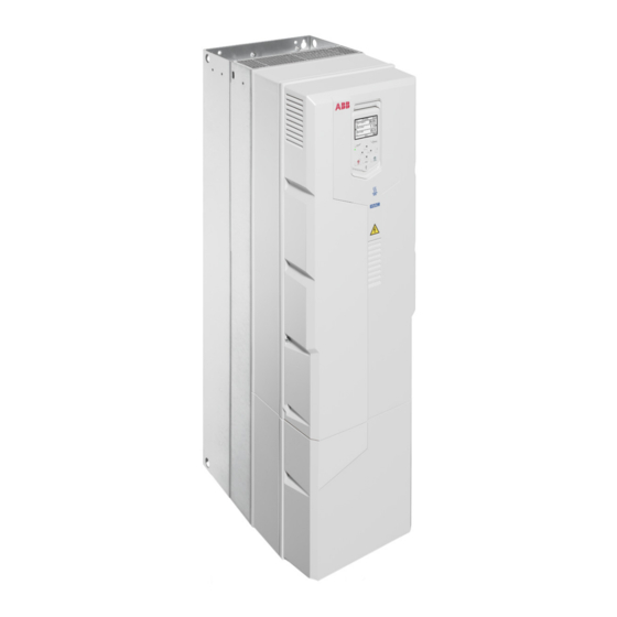
Page 34: Layout
34 Operation principle Layout IP21 (UL Type 1 R6) IP55 (UL Type 12) option +B056, R6 UL Type 12 R6 IP20 (UL Open Type) option +P940, R3 Lifting eyes (2 pcs in frame R3, 6 pcs in Front cover frames R6 and R8) Control panel Control panel behind the control panel cover... - Page 35 Operation principle 35 Auxiliary cooling fan. For frame R3 in Clamps for securing the control cables IP55 (UL Type 12) drives and for +C135 mechanically IP21 (UL Type 1) drives. Another auxiliary cooling fan at right-hand side of the control panel is included in IP55 (UL Type 12) frames R8 and frame R6 types -062A-4 and -052A-4 and bigger.
-
Page 36: Overview Of Power And Control Connections
36 Operation principle 360-degree grounding clamps for power DC cable entry cable shields 360-degree grounding clamps for con- Motor cable entry behind the 360-de- trol cable shields gree grounding clamps Control unit with I/O cable connection terminals Overview of power and control connections The logical diagram below shows the power connections and control interfaces of the drive. -
Page 37: Control Panel
Operation principle 37 Control panel To remove the control panel, press the retaining clip at the top (1a) and pull the panel forward from the top edge (1b). To install the control panel, put the bottom of the container in position (2a), press the retaining clip at the top (2b) and push the control panel in at the top edge (2c). -
Page 38: Control Panel Door Mounting Kits
CDPI-01 communication adapter module can be used to connect the drive control panel remotely to the drive, or to chain the control panel or a PC to several drives on a panel bus. The panel bus can have maximum 16 ACH580-31 drives. For more information, see CDPI-01/-02 panel bus adapters user's manual (3AXD50000009929 [English]). - Page 39 Operation principle 39...
-
Page 40: Type Designation Label
40 Operation principle Type designation label Type designation Name and address of the manufacturer Frame size (New design of frame R6 types are marked as HW v2) Cooling method and additional information Degree of protection Nominal ratings in the supply voltage range, see the technical data. Rated conditional short-circuit current, see the technical data. -
Page 41: Type Designation Key
Operation principle 41 Type designation key The type designation contains information on the specifications and configuration of the drive. The first digits from left express the basic drive type. The optional selections are given thereafter, separated by plus signs. The main selections are described below. - Page 42 42 Operation principle Code Description K465 FBIP-01 BACnet/IP adapter module, 2-port K469 FECA-01 EtherCat adapter module K470 FEPL-02 EtherPOWERLINK adapter module FENA-21 Ethernet adapter module for EtherNet/IP™, Modbus TCP and PROFINET K475 IO protocols, 2-port L501 CMOD-01 External 24 V AC/DC and digital I/O extension (2×RO and 1×DO) L512 CHDI-01 115/230 V digital input module (six digital inputs and two relay outputs) L523...
-
Page 43: Mechanical Installation
(3AUA0000107668 [English]). Flange mounting (option +C135) See also: Manual name Code (English) ACS880-11…, ACS880-31…, ACH580-31… and ACQ580-31…+C135 3AXD50000349838 drives with flange mounting kit supplement ACS880-11…, ACS880-31…, ACH580-31… and ACQ580-31…+C135 3AXD50000181506 frame R3 flange mounting kit quick installation guide ACS880-11…+C135, ACS880-31…+C135, ACH580-31…+C135 and 3AXD50000133611 ACQ580-31…+C135 frames R6 and R8 flange mounting kit quick in-... -
Page 44: Safety
44 Mechanical installation Safety WARNING! Frames R6 and R8: Lift the drive with a lifting device. Use the lifting eyes of the drive. Do not tilt the drive. The drive is heavy and its center of gravity is high. An overturning drive can cause physical injury. Examining the installation site Examine the installation site. -
Page 45: Free Space Requirements
Mechanical installation 45 • vertically side by side • horizontally alone, IP21 (UL Type 1) only. Note: The vibration specification in the technical data may not be fulfilled. Note: IP21 (UL Type 1) construction only meets IP20 (UL Type Open) in horizontal position. -
Page 46: Necessary Tools
46 Mechanical installation 200 mm (7.87 in.) 120 mm (4.72 in.) 250 mm (9.84 in.) 120 mm (4.72 in.) 300 mm (11.81 in.) Necessary tools To move a heavy drive, you need crane, fork-lift or pallet truck (check load capacity!). To lift a heavy drive, you need a hoist. -
Page 47: Moving The Drive
Mechanical installation 47 • socket set, Hex key set (metric) • tape measure, if you will not be using the provided mounting template. Moving the drive Move the drive in its transport package to the installation site. Unpacking and examining delivery The figure below shows the drive package with its contents. - Page 48 48 Mechanical installation R3 IP21 (UL Type 1) and IP55 (UL Type 12) AXD50000664825 Control panel Package cushion Mounting template Foam cushion Package straps Cardboard tray I/O option module Cardboard sleeve Fieldbus option module Cardboard box which contains control panel box 1 and option boxes 4 and 5 Printed quick installation and start-up Drive guide and manuals, multilingual resid-...
- Page 49 Mechanical installation 49 R6 IP21 (UL Type 1) 3AXD50000038252 Printed quick installation and stat-up Drive with factory installed options guide and manuals, multilingual resid- ual voltage warning sticker Accessories Outer box Mounting template Pallet Package straps VCI bag Plastic bag To unpack: •...
- Page 50 50 Mechanical installation R6 IP55 (UL Type 12) 3AXD50000038252 Printed quick installation and start-up Drive with factory installed options guide and manuals, multilingual resid- ual voltage warning sticker Accessories Outer box Bubble wrap Cardboard insert Mounting template Pallet Package straps VCI bag Plastic bag UL Type 12 hood...
- Page 51 Mechanical installation 51 R8 IP21 (UL Type 1) 3AXD50000106974 Printed quick installation and start-up Cardboard sleeve guide and manuals, multilingual resid- ual voltage warning sticker VCI bag Packing bracket Mounting template Pallet Package straps Screw Plastic bag Screw Plywood support Drive with factory installed options Tray Common mode filter (option +E208)
- Page 52 52 Mechanical installation R8 IP55 (UL Type 12) 3AXD50000106974 Printed quick installation and start-up Cardboard sleeve guide and manuals, multilingual resid- ual voltage warning sticker VCI bag Plywood support Bubble wrap Pallet Mounting template UL Type 12 hood Package straps Drive with factory installed options Plastic bag Screws...
-
Page 53: Installing The Drive Vertically
Mechanical installation 53 Installing the drive vertically See section Free space requirements (page 45) for the required free space above and below the drive. To mark the hole locations, use the mounting template included in the package. Do not leave the mounting template under the drive. The drive dimensions and hole locations are also shown in the dimension drawings. - Page 54 54 Mechanical installation R3: M5 (#10) R6: M8 (5/16 ) R8: M8 (5/16 ) 18.66 29.64 37.20 6.30 212.5 8.37 262.5 10.33 IP21, UL Type 1 21.3 61.0 IP55, UL Type 12 23.3...
-
Page 55: Installing The Drive Vertically Side By Side
Mechanical installation 55 Installing the drive vertically side by side Drives can be installed side by side. Follow the steps in section Installing the drive vertically (page 53). Installing the drive horizontally The drive can be installed with either the left or right side up. Follow the steps in section Installing the drive vertically (page 53). -
Page 57: Guidelines For Planning The Electrical Installation
ABB does not assume any liability whatsoever for any installation which breaches the local laws and/or other regulations. Furthermore, if the recommendations given by ABB are not followed, the drive may experience problems that the warranty does not cover. -
Page 58: European Union And United Kingdom
A shorter switch over time or a different phase order can cause a drive fault trip or damage to the drive. Consult ABB for implementation instructions of the fast switch over system. Selecting the main contactor You can equip the drive with a main contactor. -
Page 59: North America
Examining the compatibility of the motor and drive Use asynchronous AC induction motors, permanent magnet synchronous motors or ABB synchronous reluctance motors (SynRM motors) with the drive. Select the motor size and drive type from the rating table on basis of the AC line voltage and motor load. -
Page 60: Requirements Tables
Nominal AC line Requirement for voltage Motor insu- ABB d u /d t and common mode filters, in- lation sys- sulated N-end motor bearings P n < 100 kW and frame size < IEC 315 P n < 134 hp and frame size < NEMA 500 U n ≤... -
Page 61: Requirements For Abb Motors, P
Motor type Nominal AC line Requirement for voltage Motor insu- ABB d u /d t and common mode filters, in- lation sys- sulated N-end motor bearings 100 kW ≤ P n < 350 P n ≥ 350 kW frame size ≥... -
Page 62: Requirements For Non-Abb Motors, P < 100 Kw (134 Hp)
Nominal AC line Requirement for voltage Motor insu- ABB d u /d t and common mode filters, in- lation sys- sulated N-end motor bearings P n < 100 kW and frame size < IEC 315 P n < 134 hp and frame size < NEMA 500 U n ≤... -
Page 63: Requirements For Non-Abb Motors, P
Motor type Nominal AC line Requirement for voltage Motor insu- ABB d u /d t and common mode filters, in- lation sys- sulated N-end motor bearings 100 kW ≤ P n < 350 P n ≥ 350 kW frame size ≥... -
Page 64: Abbreviations
If you use an explosion-safe (EX) motor, obey the rules in the requirements table above. In addition, consult the motor manufacturer for any further requirements. Additional requirements for ABB motors of types other than M2_, M3_, M4_, HX_ and AM_ Use the selection criteria given for non-ABB motors. -
Page 65: Additional Requirements For Non-Abb High-Output And Ip23 Motors
The rated output power of high-output motors is higher than what is stated for the particular frame size in EN 50347 (2001). If you plan to use a non-ABB high-output motor or an IP23 motor, consider these additional requirements for protecting the motor insulation and bearings in drive systems: •... -
Page 66: Additional Data For Calculating The Rise Time And The Peak Line-To-Line Voltage
Nominal AC supply Requirement for voltage Motor insulation sys- ABB d u /d t and common mode filters, insu- lated N-end motor bearings P n < 100 kW or frame 100 kW < P n < 350 kW size < IEC 315 IEC 315 <... -
Page 67: Additional Note For Sine Filters
Guidelines for planning the electrical installation 67 Û du/dt ------------ - (1/μs) l (m) du/dt ------------ - (1/μs) Û l (m) Drive with du/dt filter Drive without du/dt filter Motor cable length Nominal AC line voltage Û LL / U n Relative peak line-to-line voltage (d u /d t )/ U n Relative d u /d t value... -
Page 68: Selecting The Power Cables
68 Guidelines for planning the electrical installation Selecting the power cables ■ General guidelines Select the input power and motor cables according to local regulations. • Current: Select a cable capable of carrying the maximum load current and suitable for the prospective short-circuit current provided by the supply network. -
Page 69: Alternate Power Cable Types
Guidelines for planning the electrical installation 69 Cable type Use as input power cabling Use as motor cabling and as brake resistor cabling Symmetrical shielded (or ar- mored) cable with three phase conductors and sym- metrically constructed PE conductor and a shield (or armor) Symmetrical shielded (or ar- mored) cable with three... -
Page 70: Not Allowed Power Cable Types
Symmetrical shielded cable with individual shields for each phase conductor ■ Additional guidelines – North America ABB recommends the use of metallic conduit for power wiring. ABB also recommends the use of symmetrical shielded VFD cable between drive and motor(s). -
Page 71: Metal Conduit
Guidelines for planning the electrical installation 71 This table shows examples of methods for wiring the drive. Refer to NFPA 70 (NEC) along with state and local codes for the appropriate methods for your application. Wiring method Notes 1) 2) Conduit - Metallic Electrical metallic tubing: Type EMT Prefer symmetrical shielded VFD cable. -
Page 72: Grounding Requirements
72 Guidelines for planning the electrical installation requirement of the motor cable shield of the drive is shown below. It consists of a concentric layer of copper wires with an open helix of copper tape or copper wire. The better and tighter the shield, the lower the emission level and bearing currents. -
Page 73: Additional Grounding Requirements - Iec
Guidelines for planning the electrical installation 73 conductor must be determined in a manner which produces a conductance equivalent to that which results from the application of this table. Cross-sectional area of the phase conduct- Minimum cross-sectional area of the corres- ponding protective earth conductor S (mm 2 ) S p (mm 2 ) -
Page 74: Additional Grounding Requirements - Ul (Nec)
Shielding Only use shielded control cables. Use a double-shielded twisted pair cable for analog signals. ABB recommends this type of cable also for the pulse encoder signals. Use one individually shielded pair for each signal. Do not use common return for different analog signals. -
Page 75: Relay Cable
■ Relay cable The cable type with braided metallic shield (for example ÖLFLEX by LAPPKABEL, Germany) has been tested and approved by ABB. ■ Control panel to drive cable Use EIA-485, Cat 5e (or better) cable with male RJ-45 connectors. The maximum length of the cable is 100 m (328 ft). -
Page 76: General Guidelines - North America
76 Guidelines for planning the electrical installation min. 300 mm (12 in) min. 300 mm (12 in) min. 500 mm (20 in) 90° min. 200 mm (8 in) min. 500 mm (20 in) Motor cable Input power cable Control cable Brake resistor or chopper cable (if any) ■... -
Page 77: Continuous Motor Cable Shield/Conduit Or Enclosure For Equipment On The Motor Cable
Guidelines for planning the electrical installation 77 Input power cabling Motor cabling Conduit ■ Continuous motor cable shield/conduit or enclosure for equipment on the motor cable To minimize the emission level when safety switches, contactors, connection boxes or similar equipment are installed on the motor cable between the drive and the motor: •... -
Page 78: Separate Control Cable Ducts
78 Guidelines for planning the electrical installation ■ Separate control cable ducts Put 24 V DC and 230 V AC (120 V AC) control cables in separate ducts, unless the 24 V DC cable is insulated for 230 V AC (120 V AC) or insulated with an insulation sleeving for 230 V AC (120 V AC). -
Page 79: Circuit Breakers
Guidelines for planning the electrical installation 79 WARNING! Due to the inherent operating principle and construction of circuit breakers, independent of the manufacturer, hot ionized gases can escape from the breaker enclosure in case of a short-circuit. To ensure safe use, pay special attention to the installation and placement of the breakers. -
Page 80: Protecting The Motor Against Thermal Overload
80 Guidelines for planning the electrical installation ■ Protecting the motor against thermal overload According to regulations, the motor must be protected against thermal overload and the current must be switched off when overload is detected. The drive includes a motor thermal protection function that protects the motor and switches off the current when necessary. -
Page 81: Connecting A Motor Temperature Sensor To The Drive Through An Option
Guidelines for planning the electrical installation 81 You have these implementation alternatives: If there is double or reinforced insulation between the sensor and the live parts of the motor: You can connect the sensor directly to the analog/digital input(s) of the drive. See the control cable connection instructions. Make sure that the voltage does not exceed the maximum allowed voltage over the sensor. -
Page 82: Protecting The Drive Against Ground Faults
82 Guidelines for planning the electrical installation Option module Temperature sensor Temperature sensor type insulation require- ment Type Insulation/Isolation Pt100, Pt1000 CMOD- Reinforced insulation between No special require- the sensor connector and other ment connectors (including drive CPTC-02 No special require- control unit connector). -
Page 83: Using Power Factor Compensation Capacitors With The Drive
Guidelines for planning the electrical installation 83 If you equip the drive with a main contactor or breaker, make sure that it restores the drive input power after a short break. The contactor must either re-connect after the break automatically, or remain closed over the break. Depending on the contactor control circuit design, this can require an additional hold circuit, uninterruptible auxiliary power supply or auxiliary power supply buffering. -
Page 84: Using A Safety Switch Between The Drive And The Motor
Using a safety switch between the drive and the motor ABB recommends to install a safety switch between the permanent magnet motor and the drive output. The switch is needed to isolate the motor from the drive during maintenance work on the drive. -
Page 85: Implementing A Bypass Connection
Guidelines for planning the electrical installation 85 WARNING! When the vector control mode is in use, never open the output contactor while the drive controls the motor. The vector control operates extremely fast, much faster than it takes for the contactor to open its contacts. When the contactor starts opening while the drive controls the motor, the vector control will try to maintain the load current by immediately increasing the drive output voltage to the maximum. -
Page 86: Example Bypass Connection
86 Guidelines for planning the electrical installation Example bypass connection An example bypass connection is shown below. Drive main switch Bypass circuit breaker Drive main contactor Bypass contactor Drive output contactor Drive main contactor on/off control Motor power supply selection (drive or direct-on-line) Start when motor is connected direct-on-line Stop when motor is connected direct-on-line ■... -
Page 87: Switching The Motor Power Supply From Direct-On-Line To Drive
Guidelines for planning the electrical installation 87 2. Open the main contactor of the drive with S11. 3. Switch the motor power supply from the drive to direct-on-line with S40. 4. Wait for 10 seconds to allow the motor magnetization to dissipate. 5. -
Page 88: Limiting Relay Output Maximum Voltages At High Installation Altitudes
88 Guidelines for planning the electrical installation Limiting relay output maximum voltages at high installation altitudes See section Isolation areas (page 145). Implementing a motor temperature sensor connection WARNING! IEC 61800-5-1 requires double or reinforced insulation between live parts and accessible parts when: •... -
Page 89: Connecting A Motor Temperature Sensor To The Drive Through An Option
Guidelines for planning the electrical installation 89 ■ Connecting a motor temperature sensor to the drive through an option module This table shows: • option module types that you can use for the motor temperature sensor connection • insulation or isolation level that each option module forms between its temperature sensor connector and other connectors •... -
Page 91: Electrical Installation - Iec
Electrical installation – IEC 91 Electrical installation – IEC Contents of this chapter This chapter contains instructions on the wiring of the drive. Safety WARNING! If you are not a qualified electrical professional, do not do installation or maintenance work. Obey the safety instructions of the drive. If you ignore them, injury or death, or damage to the equipment can occur. -
Page 92: Measuring The Insulation
Use a measuring voltage of 1000 V DC. The insulation resistance of an ABB motor must be more than 100 Mohm (reference value at 25 °C [77 °F]). For the insulation resistance of other motors, refer to the manufacturer’s instructions. -
Page 93: Measuring The Insulation Resistance Of The Brake Resistor Circuit
Electrical installation – IEC 93 U1-PE, V1-PE, W1-PE 1000 V DC, > 100 Mohm ■ Measuring the insulation resistance of the brake resistor circuit WARNING! Obey the safety instructions of the drive. If you ignore them, injury or death, or damage to the equipment can occur. If you are not a qualified electrical professional, do not do installation, commissioning or maintenance work. -
Page 94: Ground-To-Phase Varistor
94 Electrical installation – IEC to disconnect the EMC filter. See section When to disconnect EMC filter or ground-to-phase varistor: TN-S, IT, corner-grounded delta and midpoint-grounded delta systems and TT systems (page 94). WARNING! Do not install the drive with the EMC filter connected to a system that the filter is not suitable for. - Page 95 Electrical installation – IEC 95 Corner-grounded delta systems ≤ 600 V R3: Do not remove EMC or VAR screws. R6: Remove EMC screw. Do not remove VAR screw. See Note 1 below. R8: Remove EMC DC and VAR screws. Midpoint-grounded delta systems ≤ 600 V R3: Do not remove EMC or VAR screws.
- Page 96 • Because the EMC filter screws have been removed, ABB does not guarantee the EMC category. • ABB does not guarantee the functioning of the ground leakage detector built inside the drive. • In large systems the residual current device can trip without a real reason.
-
Page 97: Identifying The Grounding System Of The Electrical Power Network
Electrical installation – IEC 97 ■ Identifying the grounding system of the electrical power network WARNING! Only a qualified electrical professional may do the work instructed in this section. Depending on the installation site, the work may even be categorized as live working. -
Page 98: Disconnecting Integrated Emc Filter And Ground-To-Phase Varistor - Frame R3
98 Electrical installation – IEC ■ Disconnecting integrated EMC filter and ground-to-phase varistor – frame R3 Stop the drive and do the steps in section Electrical safety precautions (page 20) before you start the work. 2. Remove the front cover. 3. -
Page 99: Disconnecting Integrated Emc Filter And Ground-To-Phase Varistor - Frame R6
Electrical installation – IEC 99 ■ Disconnecting integrated EMC filter and ground-to-phase varistor – frame R6 Stop the drive and do the steps in section Electrical safety precautions (page 20) before you start the work. 2. Remove the front cover and the lower front cover. 3. -
Page 100: Disconnecting Integrated Emc Filter And Ground-To-Phase Varistor - Frame R8
100 Electrical installation – IEC ■ Disconnecting integrated EMC filter and ground-to-phase varistor – frame R8 Stop the drive and do the steps in section Electrical safety precautions (page 20) before you start the work. 2. Remove the front cover if it is not already removed. 3. -
Page 101: Connecting The Power Cables
Use a separate grounding cable for the motor side, if the conductivity of the shield is not sufficient, or if there is no symmetrically constructed PE conductor in the cable. ABB requires 360° grounding of the cable shield for the motor cable. ABB also recom- mends it for the input power cable. -
Page 102: Connection Procedure
The procedure of connecting the power cables to the standard drive is described below. For the procedure with UK gland plate (option +H358), see also ACS880-11, ACS880-31, ACH580-31 and ACQ580-31 UK gland plate (+H358) installation guide (3AXD50000110711 [English]). To remove the R3 front cover (R6 and R8 upper front cover), lift the cover from the bottom outwards (1a) and then up (1b). - Page 103 Electrical installation – IEC 103 R6, R8 – IP21 R6, R8 – IP55 2. Attach the residual voltage warning sticker in the local language. 3. For frames R6 and R8: Remove the shroud on the power cable terminals.
- Page 104 104 Electrical installation – IEC 4. For frame R6: If you need more working space, unscrew the screw and lift the EMC plate off. Install the EMC plate again after you have installed the motor and input power cables. For frame R8: Remove the EMC cover plates (4a). Remove the EMC side plates (4b).
- Page 105 Electrical installation – IEC 105 7. Cut an adequate hole into the rubber grommet. Slide the grommet onto the cable. 8. Prepare the ends of the cables as shown in the figure. Two different motor cable types are shown. If you use aluminum cables, put grease onto the peeled aluminum cable before you connect it to the drive.
- Page 106 • For frame R8: Install the common mode filter. For instructions, see Common mode filter kit for ACS880-01 frame R7, and for ACS880-11, ACS880-31, ACH580-31 and ACQ580-31 frame R8 installation instructions (3AXD50000015179 [English]). • Connect the phase conductors of the motor cable to the T1/U, T2/V and T3/W terminals and the phase conductors of the input cable to the L1, L2 and L3 terminals.
- Page 107 Electrical installation – IEC 107 1.7 N·m 1.7 N·m L1, L2, L3, T1/U, T2/V, T3/W, UDC+, UDC-: 1.7 N·m 1.7 N·m 2.9 N·m 2 N·m L1, L2, L3, T1/U, T2/V, T3/W, UDC+, UDC-: 2.9 N·m 15 N·m...
- Page 108 108 Electrical installation – IEC 9.8 N·m L1, L2, L3, T1/U, T2/V, T3/W, UDC+, UDC-: 30 N·m 2 N·m Note: For frame R8: Install the side plates if removed. Note: For frame R8: The power cable connectors can be detached. For the instructions, see section R8 power cable connection if you detach the cable connectors (page...
-
Page 109: R8 Power Cable Connection If You Detach The Cable Connectors
Electrical installation – IEC 109 13. Install the shroud onto the power cable connection terminals. R8 power cable connection if you detach the cable connectors The power cable connectors of frame R8 are detachable. If you detach them, you can connect the cables with cable lugs as follows: •... -
Page 110: Connecting The Control Cables
110 Electrical installation – IEC 16 N·m 30 N·m 16 N·m Connecting the control cables ■ Connection diagram Default I/O connection diagram (page 137) for the default I/O connections of the drive. ■ Connection procedure WARNING! Obey the safety instructions of the drive. If you ignore them, injury or death, or damage to the equipment can occur. - Page 111 Electrical installation – IEC 111 2. Remove the front cover(s) if not already removed. 3. For frame R3: Pull the control panel holder up. 4. Cut an adequate hole into the rubber grommet and slide the grommet onto the cable. Slide the cable through a hole in the bottom plate and attach the grommet to the hole.
- Page 112 112 Electrical installation – IEC 1.7 N·m...
- Page 113 Electrical installation – IEC 113 1.7 N·m...
- Page 114 114 Electrical installation – IEC 1.7 N·m...
-
Page 115: Installing Option Modules
Electrical installation – IEC 115 Installing option modules WARNING! Obey the safety instructions of the drive. If you ignore them, injury or death, or damage to the equipment can occur. Stop the drive and do the steps in section Electrical safety precautions (page 20) before you start the work. -
Page 116: Option Slot 1 (Fieldbus Adapter Modules)
116 Electrical installation – IEC ■ Option slot 1 (fieldbus adapter modules) Put the module carefully into its position on the control unit. 2. Tighten the mounting screw (CHASSIS) to 0.8 N·m (7 lbf·in). The screw tightens the connections and grounds the module. This is necessary for fulfilling the EMC requirements and for correct operation of the module. -
Page 117: Reinstalling Cover(S)
Electrical installation – IEC 117 Reinstalling cover(s) After installation, reinstall the covers. For IP55 (UL Type 12) frame R8, connect the secondary auxiliary cooling fan power supply wire, see section Replacing the auxiliary cooling fan in the IP55 (UL Type 12) cover, frame R8 (page 165). -
Page 118: Connecting A Pc
118 Electrical installation – IEC Connecting a PC WARNING! Do not connect the PC directly to the control panel connector of the control unit as this can cause damage. A PC (with, for example, the Drive composer PC tool) can be connected as follows: Connect a ACS-AP-…... -
Page 119: Electrical Installation - North America (Nec)
Electrical installation – North America (NEC) 119 Electrical installation – North America (NEC) Contents of this chapter The chapter describes how to check the insulation of the assembly and the compatibility with other than symmetrically grounding TN-S systems. It then shows how to connect the power and control cables, install optional modules and connect a PC. -
Page 120: Measuring The Installation
120 Electrical installation – North America (NEC) Measuring the installation See section Measuring the insulation (page 92). Grounding system compatibility check See section Grounding system compatibility check (page 93). Connecting the power cables ■ Connection diagram Note: NEC installation can include separate insulated conductors inside a conduit, shielded VFD cable in conduit, or shielded VFD cable without conduit. -
Page 121: Connection Procedure
243). If necessary, install an external filter (du/dt, common mode, or sine filter). Filters are available from ABB. Note: All openings in the drive enclosure must be closed with UL listed devices having the same Type rating as the drive Type. - Page 122 122 Electrical installation – North America (NEC) R6, R8 – UL Type 1 R6, R8 – UL Type 12 2. Attach the residual voltage warning sticker in the local language. 3. For frames R6 and R8: Remove the shroud on the power cable terminals.
- Page 123 Electrical installation – North America (NEC) 123 4. For frame R6: If you need more working space, unscrew the screw and lift the EMC plate off. Install the EMC plate again after you have installed the motor and input power cables. For frame R8: Remove the EMC cover plates (4a).
- Page 124 R6 and R8 2 N·m (1.48 lbf·ft) • For frame R8: Install the common mode filter. For instructions, see Common mode filter kit for ACS880-01 frame R7, and for ACS880-11, ACS880-31, ACH580-31 and ACQ580-31 frame R8 installation instructions (3AXD50000015179 [English]).
- Page 125 Electrical installation – North America (NEC) 125 • Connect the phase conductors of the motor cable to the T1/U, T2/V and T3/W terminals and the phase conductors of the input cable to the L1, L2 and L3 terminals. • If DC cables are present, use only two phase conductors and the ground conductor.
- Page 126 126 Electrical installation – North America (NEC) L1, L2, L3, T1/U, T2/V, T3/W, UDC+, PE (Ground): 2.9 N·m (2.1 lbf·ft) UDC-: 15 N·m (11.0 lbf·ft)
- Page 127 Electrical installation – North America (NEC) 127 L1, L2, L3, T1/U, T2/V, T3/W, UDC+, PE (Ground): 9.8 N·m (7.2 lbf·ft) UDC-: 30 N·m (22.5 lbf·ft) Do not detach the power cable connectors. For frame R8: Install the side plates if removed. 10.
-
Page 128: Connecting The Control Cables
128 Electrical installation – North America (NEC) 12. Install the shroud onto the power cable connection terminals. Connecting the control cables ■ Connection diagram See section Default I/O connection diagram (page 137). ■ Connection procedure WARNING! Obey the safety instructions of the drive. If you ignore them, injury or death, or damage to the equipment can occur. - Page 129 Electrical installation – North America (NEC) 129 4. Attach the cable conduits to the conduit plate. Make sure the conduit is correctly bonded at both ends and that conductivity is consistent throughout the conduit. Slide the control cables through the conduit. Cut to suitable length (note the extra length of the grounding conductors) and strip the conductors.
- Page 130 130 Electrical installation – North America (NEC) 250 mA...
- Page 131 Electrical installation – North America (NEC) 131...
-
Page 132: Installing Optional Modules
132 Electrical installation – North America (NEC) Installing optional modules See section Installing option modules (page 115). -
Page 133: Reinstalling Cover(S)
Electrical installation – North America (NEC) 133 Reinstalling cover(s) After installation, reinstall the covers. For UL Type 12 frame R8, connect the second auxiliary cooling fan power supply wire, see section Replacing the auxiliary cooling fan in the IP55 (UL Type 12) cover, frame R8 (page 165). -
Page 134: Connecting A Pc
134 Electrical installation – North America (NEC) Connecting a PC See section Connecting a PC (page 118). Connecting a remote panel, or chaining one panel to several drives See section Connecting a remote panel, or chaining one panel to several drives (page 118). -
Page 135: Control Unit
Control unit 135 Control unit Contents of this chapter This chapter contains the default I/O connection diagram, descriptions of the terminals and technical data for the drive control unit (CCU-24). -
Page 136: Layout
136 Control unit Layout The layout of the external control connection terminals on the drive module control unit is shown below. SLOT 1 SLOT 1 Option slot 1 (fieldbus adapter modules) ANALOG IN/OUT 1…3 Analog input 1 4…6 Analog input 2 1…3 7…9 Analog outputs... -
Page 137: Default I/O Connection Diagram
Control unit 137 Default I/O connection diagram ■ Default I/O connection diagram The default control connections for the HVAC default are shown below. Connection Term Description X1 Reference voltage and analog inputs and outputs Signal cable shield (screen) Output frequency/speed reference: 0…10 V 1) 1...10 kohm AGND... - Page 138 138 Control unit Connection Term Description Embedded fieldbus, EFB (EIA-485) DGND TERM Termination switch BIAS Bias resistors switch X4 Safe Torque Off OUT1 Safe torque off. Factory connection. Both circuits must be closed for the OUT2 drive to start.Refer to The Safe torque SGND off function (page...
-
Page 139: Switches
Control unit 139 Connected with jumpers at the factory. Use shielded twisted-pair cables for digital signals. Ground the outer shield of the cable 360° under the grounding clamp on the grounding shelf, and the pair-cable shields and grounding wire at the grounding terminal (SCR) of the control unit. -
Page 140: Npn Configuration For Digital Inputs (X2 & X3)
140 Control unit WARNING! Do not connect the +24 V AC cable to the control unit ground when the control unit is powered from an external 24 V AC supply. ■ NPN configuration for digital inputs (X2 & X3) Internal and external +24 V power supply connections for NPN configuration are shown in the figure below. -
Page 141: Di5 As Frequency Input
Control unit 141 An example of a two-wire sensor/transmitter supplied by the drive auxiliary voltage output is shown below. Set the input signal to 4…20 mA, not 0…20 mA. 4…20 mA AGND +24V DGND An example of a three-wire sensor/transmitter supplied by the drive auxiliary voltage output is shown below.The sensor is supplied through its current output and the drive feeds the supply voltage (+24 V DC). -
Page 142: Safe Torque Off (X4)
142 Control unit the shield unconnected or ground it indirectly via a few nanofarads high-frequency capacitor, for example, 3.3 nF / 630 V. The shield can also be grounded directly at both ends if they are in the same ground line with no significant voltage drop between the end points. - Page 143 Control unit 143 +24 V DC output Total load capacity of this outputs is 6.0 W (250 mA / 24 V) (Term. 10) minus the power taken by the option modules installed on board. Terminal size: 0.14 … 2.5 mm 2 (26 … 14 AWG) Digital inputs DI1…DI6 Input type: NPN/PNP Terminal size: 0.14 …...
- Page 144 144 Control unit Analog outputs AO1 and Current/voltage output mode for AO1 selected with a paramet- AO2 (Term. 7 and 8) er, see Connection for obtaining 0…10 V from analog output 2 (AO2) (page 140). Current output: 0…20 mA, R load : < 500 ohm Voltage input: 0…10 V, R load : >...
- Page 145 Control unit 145 Isolation areas SLOT 1 1…3 4…6 7…8 10…12 24 V 13…15 16…18 34…38 EIA/R5-485 40, 41 Ext. 24 V SLOT 2 19…21 22…24 25…27 Panel port Power unit connection at the bottom of the con- trol unit Reinforced insulation (IEC/EN 61800-5-1:2007, UL 61800-5-1 First edition) Functional insulation (IEC/EN 61800-5-1:2007, UL...
- Page 146 146 Control unit Ground isolation diagram Slot 1 Slot 2 AGND +10V AGND AGND X2 & X3 +24V DGND DCOM X6, X7, X8 RO1C RO1A RO1B RO2C RO2A RO2B RO3C RO3A RO3B DGND OUT1 OUT2 SGND 24VAC/DC+in 24VAC/DC-in *) Jumper installed at factory...
-
Page 147: Installation Checklist
Installation checklist 147 Installation checklist Contents of this chapter This chapter contains a checklist for the mechanical and electrical installation of the drive. Checklist Examine the mechanical and electrical installation of the drive before start-up. Go through the checklist together with another person. WARNING! Obey the safety instructions of the drive. - Page 148 148 Installation checklist Make sure that … The insulation resistance of the input power cable, motor cable and motor is meas- ured according to local regulations and the manuals of the drive. The drive is attached securely on an even, vertical and non-flammable wall. The cooling air flows freely in and out of the drive.
- Page 149 Installation checklist 149 Make sure that … There are no tools, foreign objects or dust from drilling inside the drive. The area in front of the drive is clean: the drive cooling fan cannot draw any dust or dirt inside. Drive covers and cover of the motor connection box are in place.
-
Page 151: Start-Up
[English]). Start-up procedure Run setup of the drive control program according to the start-up instructions given in ACH580-31 drives quick installation and start-up guide (3AXD50000803040 [English]) or in the firmware manual. • For drives with resistor braking: See also chapter... -
Page 153: Maintenance
Maintenance intervals The tables below show the maintenance tasks which can be done by the end user. The complete maintenance schedule is available on the Internet (https://new.abb.com/drives/services/maintenance/preventive-maintenance). For more information, consult your local ABB Service representative (www.abb.com/searchchannels). ■ Description of symbols... - Page 154 • Maintenance and component replacement intervals are based on the assumption that the equipment is operated within the specified ratings and ambient conditions. ABB recommends annual drive inspections to ensure the highest reliability and optimum performance. • Long term operation near the specified maximum ratings or ambient conditions may require shorter maintenance intervals for certain components.
-
Page 155: Cleaning The Exterior Of The Drive
Maintenance 155 Cleaning the exterior of the drive WARNING! Obey the safety instructions of the drive. If you ignore them, injury or death, or damage to the equipment can occur. If you are not a qualified electrical professional, do not do installation, commissioning or maintenance work. -
Page 156: Cleaning The Heatsink
Main fans are speed controlled. When the drive is stopped, the main fan is kept running at low speed to cool the control unit. The auxiliary fans are not speed controlled and run when the control unit is powered. Replacement fans are available from ABB. Do not use other than specified spare parts. -
Page 157: Replacing The Main Cooling Fan, Frame R3
Maintenance 157 ■ Replacing the main cooling fan, frame R3 WARNING! Obey the safety instructions of the drive. If you ignore them, injury or death, or damage to the equipment can occur. Stop the drive and do the steps in section Electrical safety precautions (page 20) before you start the work. -
Page 158: Replacing The Main Cooling Fan, Frame R6
158 Maintenance ■ Replacing the main cooling fan, frame R6 WARNING! Obey the safety instructions of the drive. If you ignore them, injury or death, or damage to the equipment can occur. Stop the drive and do the steps in section Electrical safety precautions (page 20) before you start the work. -
Page 159: Replacing The Main Cooling Fan, Frame R8
Maintenance 159 ■ Replacing the main cooling fan, frame R8 WARNING! Obey the safety instructions of the drive. If you ignore them, injury or death, or damage to the equipment can occur. Stop the drive and do the steps in section Electrical safety precautions (page 20) before you start the work. -
Page 160: Replacing The Auxiliary Cooling Fan Of Frame R3, Ip55 (Ul Type 12) And +C135 Ip21 (Ul Type 1)
160 Maintenance ■ Replacing the auxiliary cooling fan of frame R3, IP55 (UL Type 12) and +C135 IP21 (UL Type 1) WARNING! Obey the safety instructions of the drive. If you ignore them, injury or death, or damage to the equipment can occur. Stop the drive and do the steps in section Electrical safety precautions (page 20) -
Page 161: Replacing The Auxiliary Cooling Fan, Frame R6
Maintenance 161 ■ Replacing the auxiliary cooling fan, frame R6 WARNING! Obey the safety instructions of the drive. If you ignore them, injury or death, or damage to the equipment can occur. Stop the drive and do the steps in section Electrical safety precautions (page 20) before you start the work. -
Page 162: Replacing The Second Auxiliary Cooling Fan, Ip55 (Ul Type 12) Frame R6
162 Maintenance ■ Replacing the second auxiliary cooling fan, IP55 (UL Type 12) frame R6 Another auxiliary cooling fan (FAN2) at right-hand side of the control panel is included in IP55 (UL Type 12) frame R6 types -062A-4 and -052A-4 and bigger. For the replacement process, see Replacing the auxiliary cooling fan, frame R6 (page... -
Page 163: Replacing The Auxiliary Cooling Fan, Frame R8
Maintenance 163 ■ Replacing the auxiliary cooling fan, frame R8 WARNING! Obey the safety instructions of the drive. If you ignore them, injury or death, or damage to the equipment can occur. Stop the drive and do the steps in section Electrical safety precautions (page 20) before you start the work. -
Page 164: Replacing The Second Internal Auxiliary Cooling Fan, Ip55 (Ul Type 12) Frame R8
164 Maintenance ■ Replacing the second internal auxiliary cooling fan, IP55 (UL Type 12) frame R8 Stop the drive and do the steps in section Electrical safety precautions (page 20) before you start the work. 2. Remove the IP55 front cover, disconnect the power supply wire of the auxiliary cooling fan in the cover (see section Replacing the auxiliary cooling fan the IP55 (UL Type 12) cover, frame... -
Page 165: Replacing The Auxiliary Cooling Fan In The Ip55 (Ul Type 12) Cover, Frame R8
Maintenance 165 ■ Replacing the auxiliary cooling fan in the IP55 (UL Type 12) cover, frame Stop the drive and do the steps in section Electrical safety precautions (page 20) before you start the work. 2. Remove the IP55 front cover. Unplug the auxiliary cooling fan power supply wire. - Page 166 166 Maintenance *Fan arrow must point up...
-
Page 167: Capacitors
Capacitor failure is usually followed by damage to the unit and an input cable fuse failure, or a fault trip. If you think that any capacitors in the drive have failed, contact ABB. ■ Reforming the capacitors The capacitors must be reformed if the drive has not been powered (either in storage or unused) for a year or more. -
Page 168: Functional Safety Components
Note that some of the components may already have been renewed earlier, restarting their mission time. The remaining mission time of the whole circuit is however determined by its oldest component. Contact your local ABB service representative for more information. -
Page 169: Technical Data
Technical data 169 Technical data Contents of this chapter This chapter contains the technical specifications of the drive including the ratings, sizes and technical requirements, provisions for fulfilling the requirements for CE, UL and other approval marks. Electrical ratings ■ IEC ratings ACH580- Frame... -
Page 170: Ul (Nec) Ratings
170 Technical data ACH580- Frame Input Max. App. Output ratings 31-… size rat- cur- power Nominal use Light-duty use Heavy-duty ing 1) rent I max I Ld P Ld I Hd P Hd 088A-4 124.1 61.0 88.0 83.6 106A-4 73.4 145A-4 100.5 169A-4... -
Page 171: Definitions
The rise in input current can heat the input cable and fuses. To avoid heating, select an input cable and fuses according to the increased input current caused by the DC voltage boost. For more information, refer to ACH580-31, ACQ580-31, ACH580-34 and ACQ580-34 drives product note on DC voltage boost (3AXD50000769407 [English]). -
Page 172: Sizing
The power ratings are the same regardless of the supply voltage within one voltage range. Note: ABB recommends the DriveSize dimensioning tool (available from (http://new.abb.com/drives/software-tools/drivesize) for selecting the drive, motor and gear combination. -
Page 173: Surrounding Air Temperature Derating
Technical data 173 Nominal current of drive type -025A-4 exceeds the current requirement of 18.1 A. Surrounding air temperature derating Temperature range Derating All drives except IP55 (UL Type 12) drive type -206A-4 up to +40 °C No derating up to +104 °F +40…+50 °C Derate 1% for every 1 °C (1.8 °F): Calculate the output by multiplying +104…+122 °F... -
Page 174: Altitude Derating
174 Technical data Temperature range Derating IP55 (UL Type 12) drive type -206A-4 up to +40 °C No derating up to +104 °F +40 … +50 °C In the temperature range +40 … +45 °C, derate 1% for every added +104 …... -
Page 175: Switching Frequency Derating
Technical data 175 4000 m 13123 ft 0.80 3500 m 11429 ft 0.85 3000 m 0.90 9842 ft 0.95 2500 m 8202 ft 1.00 2000 m 6562 ft 1500 m 4921 ft 1000 m 3300 ft +20 °C +25 °C +30 °C +35 °C +40 °C... - Page 176 176 Technical data IEC Ratings ACH580- Derating factor (k) for the minimum switching frequencies Frame 31-… 1 kHz 2 kHz 4 kHz 8 kHz 12 kHz 3-phase U n = 400 V 09A5-4 0.74 0.52 12A7-4 0.74 0.52 018A-4 0.74 0.52 026A-4 0.74...
-
Page 177: Output Voltage Boost Derating
Technical data 177 UL (NEC) Ratings ACH580- Derating factor (k) for the minimum switching frequencies Frame 31-… 1 kHz 2 kHz 4 kHz 8 kHz 12 kHz 023A-4 0.74 0.52 027A-4 0.67 0.52 034A-4 0.67 0.52 044A-4 0.67 0.52 052A-4 0.67 0.52 065A-4... -
Page 178: Fuses (Iec)
ABB recommends the high speed aR fuses specified below. The gG fuses can be used for frame R3 if they operate rapidly enough (max. 0.1 seconds). -
Page 179: Ar Fuses Din 43653 Stud-Mount
Technical data 179 ■ aR fuses DIN 43653 stud-mount ACH580- Input cur- Ultra-rapid (aR) fuses stud-mount (one fuse per phase) Min. 31-… rent I 2 t short-cir- Nominal Voltage Bussman Type DIN cuit cur- current rating type 43653 rent A 2 s 3-phase U n = 400 V 09A5-4 25.5... -
Page 180: Ar Fuses Din 43620 Blade Style
■ gG fuses DIN 43620 blade style gG fuses can be used for frame R3 if they operate rapidly enough (max. 0.1 seconds). ABB recommends, however, aR fuses. gG fuses are not allowed for frames R6 and ACH580- Input cur- gG fuses (one fuse per phase) Min. -
Page 181: Calculating The Short-Circuit Current Of The Installation
Transformer impedance (%) Transformer rated voltage (V) Nominal apparent power of the transformer (kVA) Cable reactance (ohm) Calculation example Drive: • ACH580-31-145A-4 • supply voltage = 410 V Transformer: • rated power S = 600 kVA rated secondary voltage (supply for drive supply) U •... -
Page 182: Fuses (Ul)
100 kA symmetrical amperes (rms) at 480 V maximum when protected by the fuses described below. ABB recommends Class T fuses listed below. Also allowed are UL Listed 248-8 Class J fast acting, time delay, and high speed fuses, 248-4 Class CC fast acting fuses and 248-17 Class CF fast acting and time delay fuses of the same nominal voltage and current rating. - Page 183 2. Fuses with a higher current rating than specified must not be used. 3. The UL listed fuses recommended by ABB are the required branch circuit protection per NEC. Circuit breakers listed in section Circuit breakers (UL) are also acceptable as branch circuit protection.
-
Page 184: Circuit Breakers (Iec)
You can use the circuit breakers listed below. Other circuit breakers can be used with the drive if they provide the same electrical characteristics. ABB does not assume any liability whatsoever for the correct function and protection with circuit breakers not listed below. -
Page 185: Circuit Breakers (Ul)
Technical data 185 ACH580- Frame ABB moulded case circuit breaker (Tmax) 31-… Type 026A-4 XT2H 160 EKIP DIP LS/I IN 63 033A-4 XT2H 160 EKIP DIP LS/I IN 100 039A-4 XT2H 160 EKIP DIP LS/I IN 100 046A-4 XT2H 160 EKIP DIP LS/I IN 100... - Page 186 Note: Circuit breakers are not yet validated as protection device for R6 frame “HW V2”. R6 frame “HW V2” variants must use fuses. “HW V2” is shown in the type designation label. ACH580- Frame Input Drive ABB circuit breaker Max. Max. I 31-… current Maxim- Voltage...
- Page 187 Use drive volume for all three types listed in the table when installing multiple drives in the enclosure. 7. The ABB circuit breaker part number listed in the table is a base part number. • Symbol α represents 80% or 100% allowable continuous current. Options allowed are U, Q, C and D.
-
Page 188: Dimensions, Weights And Free Space Requirements
188 Technical data Dimensions, weights and free space requirements Frame Weight Weight Height Height Width Width Depth Depth size IP21 (UL Type 1) 21.3 19.49 8.07 13.94 30.35 9.92 15.44 11.81 17.24 IP55 (UL Type 12 ), option +B056 21.3 19.49 8.07 14.17... -
Page 189: Package Dimensions And Weights
Technical data 189 ■ Package dimensions and weights [26.61] [11.38] [15.75] [19.76] [45.59]... -
Page 190: Losses, Cooling Data And Noise
This table shows typical heat loss values, required air flow and noise at the nominal ratings of the drive. The heat loss values can vary depending on voltage, cable conditions, motor efficiency and power factor. To obtain more accurate values for given conditions, use ABB DriveSize tool (http://new.abb.com/drives/software-tools/drivesize). ACH580-... - Page 191 Technical data 191 ACH580- Heat dissipation Air flow Noise Frame 31-… Main cir- Control Control Main cir- cuit at circuit circuit cuit and rated I 1 minim- maxim- control at I 2 boards m 3 /h ft 3 /min dB(A) 09A5-4 12A7-4 018A-4...
-
Page 192: Cooling Air Flow And Heat Dissipation For Flange Mounting (Option +C135)
192 Technical data UL (NEC) ACH580- Heat dissipation Air flow Noise Frame 31-… Main cir- Control Control Main cir- cuit at circuit circuit cuit and rated I 1 minim- maxim- control at I 2 boards m 3 /h ft 3 /min dB(A) 065A-4 1187... - Page 193 Technical data 193 ACH580- Heat dissipation (op- Air flow (option +C135) Frame 31-… tion +C135) Heatsink Front Heatsink Front m 3 /h ft 3 /min m 3 /h ft 3 /min 09A5-4 12A7-4 018A-4 026A-4 033A-4 039A-4 046A-4 062A-4 073A-4 1128 088A-4 1458...
-
Page 194: Terminal And Entry Data For The Power Cables
194 Technical data Terminal and entry data for the power cables ■ Input, motor and DC cable entries, maximum wire sizes (per phase) and terminal screw sizes and tightening torques are given below. Frame Cable entries L1, L2, L3, T1/U, T2/V, T3/W, UD+, UDC- terminals PE terminal Ø... -
Page 195: Terminal And Entry Data For The Control Cables
Technical data 195 • The maximum number of conductors per terminal is 1. Note: Only copper cables are allowed for drive types up to -039A-4. Terminal and entry data for the control cables ■ Control cable entries, wire sizes and tightening torques ( T ) are given below. Frame Cable entries Control cable entries and terminal sizes... - Page 196 196 Technical data IEC 1) UL (NEC) 3) ACH580- Frame 31-… size Al cable type 2) Cu cable type Cu cable type mm 2 mm 2 AWG/kcmil 12A7-4 3×2.5 018A-4 3×2.5 026A-4 3×6 033A-4 3×10 3×16 039A-4 3×10 3×16 046A-4 3×16 3×25 062A-4...
- Page 197 Technical data 197 IEC 1) UL (NEC) 3) ACH580- Frame 31-… size Al cable type 2) Cu cable type Cu cable type mm 2 mm 2 AWG/kcmil 065A-4 3×35 3×50 077A-4 3×35 3×50 096A-4 3×50 3×70 124A-4 3×70 3×95 156A-4 3×95 3×150 180A-4...
-
Page 198: Electrical Power Network Specification
198 Technical data Electrical power network specification Voltage ( U 1 ) ACH580-31-xxxx-4 drives: 380...480 V AC 3-phase +10%…-15%. This is indicated in the type designation label as typical input voltage levels 3~400/480 V AC. Network type Public low voltage networks. TN (grounded) and IT (ungrounded) systems. - Page 199 Technical data 199 Harmonic distortion Harmonics are below the limits defined in IEEE 519-2014, and G5/4. The drive complies with IEC 61000-3-2, IEC 61000-3-4 and IEC 61000- 3-12. The table below shows typical values of the drive for short-circuit ratio ( I sc / I 1 ) of 20 to 100. The values will be met if the supply network voltage is not distorted by other loads and when the drive operates at nominal load.
-
Page 200: Motor Connection Data
The de- crease depends on the motor cable length and characteristics. Contact ABB for more information. Note that a sine filter (optional) at the drive output also causes a voltage decrease. Note: Conducted and radiated emissions of these motor cable lengths do not comply with EMC requirements. -
Page 201: Ccu-24 Control Unit Connection Data
Technical data 201 EMC compatibility and motor cable length To comply with the European EMC Directive (standard EN 61800-3), use the following maximum motor cable lengths at 4 kHz switching frequency. See the table below. Frame size Maximum motor cable length, 4 kHz EMC limits for Category C2 1) Standard drive with the integrated EMC filter. -
Page 202: Protection Classes For Module
Colors Drive enclosure: RAL 9002, PMS 653 C. Materials ■ Drive Refer to Recycling instructions and environmental information ACS880-11, ACS880-31, ACH580-31 and ACQ580-31 drives (3AXD50000137671 [English]). ■ Package materials for small wall-mounted drives and converter modules • Cardboard • Molded pulp •... -
Page 203: Package Materials For Options, Accessories And Spare Parts
IEC 62635 guidelines. To aid recycling, plastic parts are marked with an appropriate identification code. Contact your local ABB distributor for further information on environmental aspects and recycling instructions for professional recyclers. End of life treatment must follow international and local regulations. -
Page 204: Ambient Conditions
204 Technical data IEC/EN 61000-3- Electromagnetic compatibility (EMC) - Part 3-12: Limits - Limits for 12:2011 harmonic currents produced by equipment connected to public low- voltage systems with input current > 16 A and < 75 A per phase. IEC 61000-3-4:1998 Limits - Limitation of emission of harmonic currents in low-voltage power supply systems for equipment with rated current greater than 16 A... -
Page 205: Markings
Technical data 205 Relative humidity 5 to 95% Max. 95% Max. 95% No condensation allowed. Maximum allowed relative humidity is 60% in the presence of corrosive gases. Contamination levels IEC 60721-3-3: 2002 IEC 60721-3-1: 1997 IEC 60721-3-2: 1997 (IEC 60721-3-x) Chemical gases Class 3C2 Class 1C2... -
Page 206: Compliance With The En 61800-3:204 + A1:2012
Product is compliant with the People’s Republic of China Electronic Industry Standard (SJ/T 11364-2014) about hazardous substances. The EFUP is 20 years. China RoHS II Declaration of Conformity is available from https://library.abb.com. WEEE mark At the end of life the product should enter the recycling system at an appropriate collection point and not placed in the normal waste stream. -
Page 207: Category C2
Technical data 207 electromagnetic environment. Likewise, the equipment must not disturb or interfere with any other product or system within its locality. First environment includes establishments connected to a low-voltage network which supplies buildings used for domestic purposes. Second environment includes establishments connected to a network not supplying domestic premises. -
Page 208: Category C3
208 Technical data Note: Note: Do not install a drive with the internal EMC filter connected to a system that the filter is not suitable for. This can cause danger, or damage the drive. Note: Do not install a drive with the ground-to-phase varistor connected to a system that the varistor is not suitable for. -
Page 209: Ul Checklist
Technical data 209 Medium voltage network Equipment Neighboring network Supply transformer Point of measurement Static screen Low voltage Drive Equipment (victim) 2. An EMC plan for preventing disturbances is drawn up for the installation. A template is available in Technical guide No. 3 EMC compliant installation and configuration for a power drive system (3AFE61348280 [English]). -
Page 210: Declarations Of Conformity
(or better). Declarations of conformity You can find declarations of conformity in PDF format on the Internet at www.abb.com/drives/documents. For EU and UK declarations of conformity, see chapter The Safe torque off function (page 221). -
Page 211: Design Lifetime Expectancy
Notwithstanding any other provision to the contrary and regardless of whether the contract is terminated or not, ABB and its affiliates are under no circumstances liable for damages and/or losses related to such security breaches, any unauthorized access, interference, intrusion, leakage and/or theft of data or... -
Page 213: Dimension Drawings
Dimension drawings 213 Dimension drawings This chapter shows the dimension drawings of the drive. The dimensions are given in millimeters and [inches]. For dimension drawings of option +P940, refer to ACS580…, ACH580… and ACQ580…+P940 and +P944 drive modules supplement (3AXD50000210305 [English]). -
Page 214: R3, Ip21 (Ul Type 1)
214 Dimension drawings R3, IP21 (UL Type 1) -
Page 215: R3 - Option +B056 (Ip55, Ul Type 12)
Dimension drawings 215 R3 – Option +B056 (IP55, UL Type 12) -
Page 216: R6, Ip21 (Ul Type 1)
216 Dimension drawings R6, IP21 (UL Type 1) -
Page 217: R6 - Option +B056 (Ip55, Ul Type 12)
Dimension drawings 217 R6 – Option +B056 (IP55, UL Type 12) -
Page 218: R8, Ip21 (Ul Type 1)
218 Dimension drawings R8, IP21 (UL Type 1) -
Page 219: R8 - Option +B056 (Ip55, Ul Type 12)
Dimension drawings 219 R8 – Option +B056 (IP55, UL Type 12) -
Page 221: The Safe Torque Off Function
The Safe torque off function 221 The Safe torque off function Contents of this chapter This chapter describes the Safe torque off (STO) function of the drive and gives instructions for its use. Description The Safe torque off function can be used, for example, as the final actuator device of safety circuits (such as an emergency stop circuit) that stop the drive in case of danger. -
Page 222: Compliance With The European Machinery Directive And The Uk Supply Of Machinery (Safety) Regulations
222 The Safe torque off function Standard Name IEC 61000-6-7:2014 Electromagnetic compatibility (EMC) – Part 6-7: Generic standards – Immunity requirements for equipment intended to perform functions in a safety-related system (functional safety) in industrial locations IEC 61326-3-1:2017 Electrical equipment for measurement, control and laborat- ory use –... -
Page 223: Wiring
The Safe torque off function 223 Wiring For the electrical specifications of the STO connection, see the technical data of the control unit. ■ Connection principle Single ACH580-31 drive, internal power supply OUT1 + 24 V DC OUT2 + 24 V DC SGND... -
Page 224: Single Ach580-31 Drive, External Power Supply
224 The Safe torque off function Single ACH580-31 drive, external power supply 24 V DC OUT1 + 24 V DC OUT2 + 24 V DC SGND UDC+ UDC- Drive Control unit Control logic To motor Activation switch ■ Wiring examples... -
Page 225: Single Ach580-31 Drive, External Power Supply
The Safe torque off function 225 Safety relay Single ACH580-31 drive, external power supply 24 V DC OUT1 OUT2 SGND Drive Safety PLC Safety relay... -
Page 226: Multiple Ach580-31 Drives, Internal Power Supply
226 The Safe torque off function Multiple ACH580-31 drives, internal power supply OUT1 + 24 V DC OUT2 + 24 V DC SGND OUT1 OUT2 SGND OUT1 OUT2 SGND Drive Control unit Activation switch... -
Page 227: Multiple Ach580-31 Drives, External Power Supply
The Safe torque off function 227 Multiple ACH580-31 drives, external power supply 24 V DC – OUT1 + 24 V DC OUT2 + 24 V DC SGND OUT1 OUT2 SGND OUT1 OUT2 SGND Drive Control unit Activation switch... -
Page 228: Activation Switch
A CPTC thermistor protection module or an FSPS safety functions module can also be used. For more information, see the module documentation. ■ Cable types and lengths • ABB recommends double-shielded twisted-pair cable. • Maximum cable lengths: • 300 m (1000 ft) between activation switch [K] and drive control unit •... -
Page 229: Operation Principle
The Safe torque off function 229 Operation principle The Safe torque off activates (the activation switch is opened, or safety relay contacts open). 2. The STO inputs of the drive control unit de-energize. 3. The control unit cuts off the control voltage from the output IGBTs. 4. -
Page 230: Start-Up Including Validation Test
230 The Safe torque off function Start-up including validation test To ensure the safe operation of a safety function, validation is required. The final assembler of the machine must validate the function by performing a validation test. The test must be performed at initial start-up of the safety function 2. - Page 231 The Safe torque off function 231 Action Test the operation of the STO function when the motor is stopped. • Give a stop command for the drive (if running) and wait until the motor shaft is at a standstill. Make sure that the drive operates as follows: •...
-
Page 232: Use
232 The Safe torque off function Open the activation switch, or activate the safety functionality that is wired to the STO connection. 2. The STO inputs on the drive control unit de-energize, and the control unit cuts off the control voltage from the output IGBTs. 3. - Page 233 The Safe torque off function 233 causes danger or is not otherwise acceptable, stop the drive and machinery using the appropriate stop mode before activating the Safe torque off function. • The Safe torque off function overrides all other functions of the drive. •...
-
Page 234: Maintenance
If any wiring or component change is needed after start-up, or the parameters are restored, do the test given in section Validation test procedure (page 230). Use only spare parts approved by ABB. Record all maintenance and proof test activities in the machine logbook. ■ Competence... -
Page 235: Fault Tracing
See the firmware manual of the drive control program for the indications generated by the drive, and for details on directing fault and warning indications to an output on the control unit for external diagnostics. Any failures of the Safe torque off function must be reported to ABB. -
Page 236: Safety Data
236 The Safe torque off function Safety data The safety data for the Safe torque off function is given below. Note: The safety data is calculated for redundant use, and applies only if both STO channels are used. - Page 237 The Safe torque off function 237...
-
Page 238: Terms And Abbreviations
238 The Safe torque off function • The following temperature profile is used in safety value calculations: • 670 on/off cycles per year with Δ T = 71.66 °C • 1340 on/off cycles per year with Δ T = 61.66 °C •... - Page 239 The Safe torque off function 239 Term or Reference Description abbreviation MTTF D EN ISO 13849-1 Mean time to dangerous failure: (Total number of life units) / (Number of dangerous, undetected failures) during a particular measurement interval under stated conditions PFD avg IEC 61508 Average probability of dangerous failure on demand,...
-
Page 240: Tüv Certificate
The product(s) referred in this Declaration of conformity fulfil(s) the relevant provisions of other European Union Directives which are notified in Single EU Declaration of conformity 3AXD10000497691. Authorized to compile the technical file: ABB Oy, Hiomotie 13, 00380 Helsinki, Finland. Helsinki, August 31, 2022... - Page 241 The product(s) referred in this declaration of conformity fulfil(s) the relevant provisions of other UK statutory requirements, which are notified in a single declaration of conformity 3AXD10001325928. Authorized to compile the technical file: ABB Limited, Daresbury Park, Cheshire, United Kingdom, WA4 4BT. Helsinki, August 31, 2022...
-
Page 243: Resistor Braking
Resistor braking 243 Resistor braking Contents of this chapter This chapter describes how to select, protect and wire brake choppers and resistors. The chapter also contains technical data. Operation principle The brake chopper handles the energy generated by a decelerating motor. The extra energy increases the DC link voltage. -
Page 244: Selecting A Custom Brake Resistor
■ Selecting a custom brake resistor If you do not use an ABB resistor, make sure that the resistance of the custom resistor is greater than or equal to the resistance of the default ABB resistor. -
Page 245: Selecting And Routing The Brake Resistor Cables
IGBT semiconductors of the brake chopper. Note: ABB has not verified that the EMC requirements are fulfilled with custom brake resistors and cabling. The customer must consider the EMC compliance of the complete installation. -
Page 246: Placing The Brake Resistors
The drive has a brake thermal model which protects the brake resistor against overload. ABB recommends to enable the thermal model at start up. ABB recommends to equip the drive with a main contactor for safety reasons even when you have enabled the resistor thermal model. Wire the contactor so that it opens in case the resistor overheats. -
Page 247: Protecting The Resistor Cable Against Short-Circuits
Resistor braking 247 ABB recommends that you also wire the thermal switch to a digital input of the drive, and configure the input to cause a fault trip at resistor overtemperature indication. Θ +24V Drive input power connection with a main contactor... -
Page 248: Connection Diagram
248 Resistor braking ■ Connection diagram See section Connection diagram (page 101). ■ Connection procedure Connect the brake chopper the DC+ and DC- terminals of the drive. Connect the resistor cables to the brake chopper as described in the brake chopper manual. If a shielded three-conductor cable is used, cut the third conductor, insulate it, and ground the twisted shield of the cable (protective earth conductor of the resistor assembly) at both ends. -
Page 249: Technical Data
In this case, the brake resistor must be disconnected. Technical data ■ Ratings Contact ABB for the brake chopper and resistor specifications. ■ Terminals and cable entry data See section Terminal and entry data for the power cables (page... -
Page 251: Common Mode, D U /D T And Sine Filters
For installation instructions, refer to • Common mode filter kit for ACS880-01 frame R7, and for ACS880-11, ACS880-31, ACH580-31 and ACQ580-31 frame R8 installation instructions (3AXD50000015179 [English]). d u /d t filters ■... -
Page 252: D U /D T Filter Types
252 Common mode, d u /d t and sine filters ■ d u /d t filter types ACH580- du/dt filter type 31-… IEC ratings: U n = 400 V 09A5-4 NOCH0016-6x 12A7-4 NOCH0016-6x 018A-4 NOCH0016-6x or NOCH0030-6x 026A-4 NOCH0030-6x 033A-4 NOCH0070-6x 039A-4 NOCH0070-6x... -
Page 253: Description, Installation And Technical Data Of The Filters
Description, installation and technical data of the filters See AOCH and NOCH du/dt filters hardware manual (3AFE58933368 [English]) or FOCHxxx-xx du/dt filters hardware manual (3AFE68577519 [English]). Sine filters See section Examining the compatibility of the motor and drive (page 59). Contact ABB for sine filter specifications. -
Page 255: Caio-01 Bipolar Analog I/O Adapter Module
CAIO-01 bipolar analog I/O adapter module 255 CAIO-01 bipolar analog I/O adapter module Contents of this chapter This chapter describes how to install and start up the optional CAIO-01 multifunction extension module. The chapter also contains diagnostics and technical data. Product overview The CAIO-01 bipolar analog I/O module expands the inputs and outputs of the drive control unit. -
Page 256: Layout
256 CAIO-01 bipolar analog I/O adapter module Layout 1, 2, 3 Analog inputs 4, 5 Analog outputs SHIELD Cable shield connection SHIELD Cable shield connection AI3+ Analog input 3 positive signal Analog output 3 signal AI3- Analog input 3 negative signal AGND Analog ground potential SHIELD... -
Page 257: Mechanical Installation
CAIO-01 bipolar analog I/O adapter module 257 Mechanical installation ■ Necessary tools • Screwdriver and a set of suitable bits. ■ Unpacking and examining the delivery Open the option package. Make sure that the package contains: • the option module •... -
Page 258: Start-Up
258 CAIO-01 bipolar analog I/O adapter module CAIO-01 SHIELD 90 80 SHIELD AI-3 AO-3 AI +VE AO + 91 AI -VE GND 92 SHIELD 93 83 SHIELD AI-4 AO-4 AI +VE AO + 94 AI -VE GND 95 86 SHIELD 0-11 V, 0-22 mA AI +VE AI-5... -
Page 259: Diagnostics
CAIO-01 bipolar analog I/O adapter module 259 Diagnostics ■ LEDs The adapter module has one diagnostic LED. Color Description Green The adapter module is powered up. There is no communication with the drive control unit or the adapter module has detected an error. Technical data Installation Into slot 2 of drive control unit... -
Page 260: Isolation Areas
260 CAIO-01 bipolar analog I/O adapter module ■ Isolation areas Plugged to drive control unit SLOT 2 Reinforced insulation (IEC 61800-5-1:2007) -
Page 261: Dimension Drawings
CAIO-01 bipolar analog I/O adapter module 261 Dimension drawings The dimensions are in millimeters. -
Page 263: Chdi-01 115/230 V Digital Input Extension Module
CHDI-01 115/230 V digital input extension module 263 CHDI-01 115/230 V digital input extension module Contents of this chapter This chapter describes how to install and start up the optional CHDI-01 multifunction extension module. The chapter also contains diagnostics and technical data. -
Page 264: Layout And Connection Examples
264 CHDI-01 115/230 V digital input extension module Layout and connection examples 3-pin terminal blocks for 115/230 V in- Relay outputs puts RO4C 115/230 V AC HDI7 RO4A 24 V DC HDI8 RO4B NEUTRAL HDI7 115/230 V input 1 RO4C Common, C HDI8 115/230 V input 2... -
Page 265: Mechanical Installation
CHDI-01 115/230 V digital input extension module 265 Mechanical installation ■ Necessary tools • Screwdriver and a set of suitable bits. ■ Unpacking and examining the delivery Open the option package. Make sure that the package contains: • the option module •... -
Page 266: Parameter Setting Example For Relay Output
266 CHDI-01 115/230 V digital input extension module You can now see the parameters of the extension module in parameter group 15 I/O extension module. 3. Set the parameters of the extension module to applicable values. Parameter setting example for relay output This example shows how make the relay output RO4 of the extension module indicate the reverse direction of rotation of the motor with a one-second delay. -
Page 267: Dimension Drawing
CHDI-01 115/230 V digital input extension module 267 CHDI-01 Plugged to drive SLOT2 Reinforced insulation (IEC 61800-5-1:2007) Functional insulation (IEC 61800-5-1:2007) Dimension drawing The dimensions are in millimeters and [inches]. -
Page 269: Cmod-01 Multifunction Extension Module
CMOD-01 multifunction extension module (external 24 V AC/DC and digital I/O) 269 CMOD-01 multifunction extension module (external 24 V AC/DC and digital I/O) Contents of this chapter This chapter describes how to install and start up the optional CMOD-01 multifunction extension module. The chapter also contains diagnostics and technical data. -
Page 270: Layout And Example Connections
270 CMOD-01 multifunction extension module (external 24 V AC/DC and digital I/O) Layout and example connections Grounding screw Diagnostic LED Hole for mounting screw 2-pin terminal block for external power 3-pin terminal blocks for relay out- supply puts RO4C 24V AC/DC + in RO4A 24 V DC 24 V AC/DC... -
Page 271: Mechanical Installation
CMOD-01 multifunction extension module (external 24 V AC/DC and digital I/O) 271 DO1 OUT Digital or frequency out- RO5A Normally closed, NC DO1 SGND Ground (earth) potential RO5B Normally open, NO 1) Digital output connection example 2) An externally supplied frequency indicator which provides, for example: •... -
Page 272: Start-Up
272 CMOD-01 multifunction extension module (external 24 V AC/DC and digital I/O) WARNING! Do not connect the +24 V AC cable to the control unit ground when the control unit is powered using an external 24 V AC supply. Start-up ■... -
Page 273: Diagnostics
CMOD-01 multifunction extension module (external 24 V AC/DC and digital I/O) 273 Parameter setting example for frequency output This example shows how to make digital output DO1 of the extension module indicate the motor speed 0…1500 rpm with a frequency range of 0…10000 Hz. Parameter Setting 15.22 DO1 configuration... -
Page 274: Dimension Drawing
274 CMOD-01 multifunction extension module (external 24 V AC/DC and digital I/O) Maximum load 4 kohm Maximum switching 30 V DC voltage Maximum switching 100 mA / 30 V DC, short-circuit protected current Frequency 10 Hz … 16 kHz Resolution 1 Hz Inaccuracy 0.2%... - Page 275 CMOD-01 multifunction extension module (external 24 V AC/DC and digital I/O) 275...
-
Page 277: Cmod-02 Multifunction Extension Module (External 24 V Ac/Dc And Isolated Ptc Interface)
CMOD-02 multifunction extension module (external 24 V AC/DC and isolated PTC interface) 277 CMOD-02 multifunction extension module (external 24 V AC/DC and isolated PTC interface) Contents of this chapter This chapter describes how to install and start up the optional CMOD-02 multifunction extension module. -
Page 278: Layout And Example Connections
278 CMOD-02 multifunction extension module (external 24 V AC/DC and isolated PTC interface) There is reinforced insulation between the motor thermistor connection, the relay output and the drive control unit interface. Thus, you can connect a motor thermistor to the drive through the extension module. With CCU-24 control unit, a CMOD-02 module is not necessary for external 24 V AC/DC supply connection. -
Page 279: Mechanical Installation
CMOD-02 multifunction extension module (external 24 V AC/DC and isolated PTC interface) 279 Motor thermistor connection Grounding screw PTC IN PTC IN One to six PTC thermistors connected in series. PTC IN PTC connection Hole for mounting screw PTC IN Ground (earth) potential Diagnostic LED Mechanical installation... -
Page 280: Start-Up
280 CMOD-02 multifunction extension module (external 24 V AC/DC and isolated PTC interface) WARNING! Do not connect the +24 V AC cable to the control unit ground when the control unit is powered using an external 24 V AC supply. Start-up ■... -
Page 281: Dimension Drawing
CMOD-02 multifunction extension module (external 24 V AC/DC and isolated PTC interface) 281 PTC terminal current < 1 mA Short-circuit detec- < 50 ohm ±10% tion The PTC input is reinforced/double insulated. If the motor part of the PTC sensor and wiring are reinforced/double insulated, voltages on the PTC wiring are within SELV limits. - Page 282 282 CMOD-02 multifunction extension module (external 24 V AC/DC and isolated PTC interface)
-
Page 283: Further Information
Product and service inquiries Address any inquiries about the product to your local ABB representative, quoting the type designation and serial number of the unit in question. A listing of ABB sales, support and service contacts can be found by navigating to www.abb.com/searchchannels. - Page 284 3AXD50000037066F © Copyright 2022 ABB. All rights reserved. Specifications subject to change without notice.