Dell PowerProtect DM5500 Installation Manual
Data manager appliance
Hide thumbs
Also See for PowerProtect DM5500:
- Installation manual (51 pages) ,
- Quick start manual (2 pages)

Related Manuals for Dell PowerProtect DM5500


Summary of Contents for Dell PowerProtect DM5500
- Page 1 Dell PowerProtect Data Manager Appliance 5.12.0.1 Installation Guide for DM5500 November 2022 Rev. 01...
- Page 2 A WARNING indicates a potential for property damage, personal injury, or death. © 2022 Dell Inc. or its subsidiaries. All rights reserved. Dell Technologies, Dell, and other trademarks are trademarks of Dell Inc. or its subsidiaries. Other trademarks may be trademarks of their respective owners.
-
Page 3: Table Of Contents
Contents Figures............................5 Tables............................6 Preface......................................7 Chapter 1: Overview........................10 PowerProtect Data Manager Appliance introduction....................10 DM5500 front and internal views..........................10 DM5500 rear view................................15 Hardware and software required for installation......................16 Third-party rack requirements ............................16 Chapter 2: Install the DM5500 in the rack..................18 Rack rails.................................... - Page 4 Assign static IP address to the service computer for initial DM5500 login............40 Chapter 6: Configure the DM5500 in the Data Manager Appliance Configuration UI....42 Log in to the Data Manager Appliance Configuration UI ..................42 Initial DM5500 configuration in the Data Manager Appliance Configuration UI..........43 Log in to the Data Manager Appliance UI ........................
-
Page 5: Figures
Figures DM5500 front view..............................10 Left control panel..............................11 Right control panel..............................11 Drive indicators................................. 12 View of drive bays extended..........................13 24 TB useable capacity DM5500 drive configuration..................14 96 TB useable capacity DM5500 drive configuration..................14 DM5500 back panel features..........................15 L-Bracket Static rail.............................. -
Page 6: Tables
Tables Revision history................................7 Typographical conventions............................8 System health and system ID indicator codes....................11 iDRAC Direct LED indicator codes........................11 Drive indicator codes............................... 12 Hardware and software requirements for DM5500 installation..............16 Static rails...................................18 Static rails adjustability............................18 DM5500 NIC combinations........................... 34 Network cabling requirements.......................... -
Page 7: Preface
Customer Support website. Purpose This document provides information on the hardware, software, and rack cabling requirements for the Dell PowerProtect DM5500 Appliance installation and configuration. Audience This document guide is designed for personnel who install, configure, and maintain the DM5500 Appliance. -
Page 8: Typographical Conventions
Typographical conventions Table 2. Typographical conventions Bold Used for names of interface elements, such as names of windows, dialog boxes, buttons, fields, tab names, key names, and menu paths (what the user specifically selects or clicks) Italic Used for full titles of publications referenced in text Monospace Used for: ●... - Page 9 Interactively engage with customers, partners, and certified professionals online. Reporting vulnerabilities Dell takes reports of potential vulnerabilities in our products seriously. For the latest on how to report a security issue to Dell, see the Dell Vulnerability Response Policy web page.
-
Page 10: Chapter 1: Overview
The Dell PowerProtect Data Manager Appliance model DM5500 is an integrated solution that offers industry-leading de- duplication and data protection solutions. The PowerProtect DM5500 Appliance is a Dell PowerEdge R740xd2 one-node server (2U) server with two drive bays. Each drive bay has 12 drives for a total of 24 drives. The DM5500 Appliance supports 12 x 32 GB DIMMs with 12 TB to 96 TB storage capacity. -
Page 11: Left Control Panel
Control panels Figure 2. Left control panel 1. System health and system ID indicator 2. Drive indicator Table 3. System health and system ID indicator codes System health and system ID Condition indicator code Solid blue Indicates that the system is turned on, system is healthy, and system ID mode is not active. -
Page 12: Drive Indicators
Drive indicator codes The LEDs on the drive carrier indicates the state of each drive. Each drive carrier in your system has two LEDs: an activity LED (green) and a status LED (bicolor, green/amber). The activity LED flashes whenever the drive is accessed. Figure 4. -
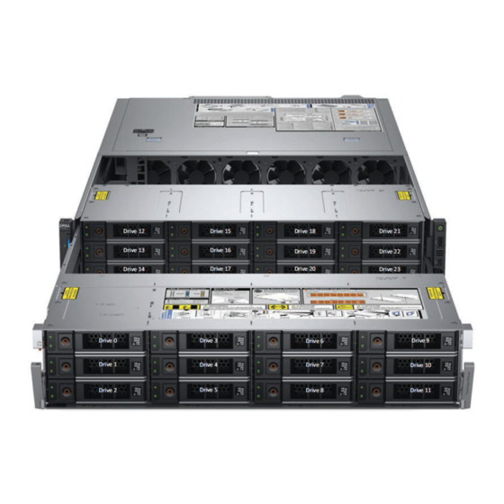
Page 13: View Of Drive Bays Extended
DM5500 internal view Drive 12 Drive 15 Drive 18 Drive 21 Drive 13 Drive 16 Drive 19 Drive 22 Drive 14 Drive 17 Drive 20 Drive 23 Drive 0 Drive 3 Drive 6 Drive 9 Drive 1 Drive 4 Drive 7 Drive 10 Drive 5 Drive 11... -
Page 14: Tb Useable Capacity Dm5500 Drive Configuration
Drive bay 1 Drive 0 Drive 3 Drive 6 Drive 9 960 GB Filler 12 TB 12 TB Boot drives Drive 1 Drive 4 Drive 7 Drive 10 Internal 960 GB 12 TB 12 TB 12 TB storage drives Cache Drive 5 Drive 8 Drive 11... -
Page 15: Dm5500 Rear View
The 96 TB useable storage capacity drive configuration includes two operating system boot disk drives, two SSDs for cache tier, two 12 TB disk drives for internal system storage, and 18 12 TB disk drives for customer storage capacity. Drive 0 960 GB SAS SSD - system boot drive Drive 1 960 GB SAS SSD - system boot drive... -
Page 16: Hardware And Software Required For Installation
If LC-to-LC optical cables are used (instead of twinax cables), 4 x 10/25 GbE SFPs can be ordered as a kit from Dell. Use the SFPs provided by Dell when connecting the 4 GbE ports on the DM5500 to the customer network. - Page 17 For customer-provided PDUs, the Dell power cords on the appliance have NEMA 5-15P connections to the PDUs. NOTE: Dell is not responsible for any failures, issues, or outages resulting from failure of the customer-provided PDUs. Weight Customer rack and data center floor must be capable of supporting the weight of DM5500 equipment.
-
Page 18: Chapter 2: Install The Dm5500 In The Rack
Install the DM5500 in the rack Topics: • Rack rails • Installing the rails • Installing the chassis retention brackets • Unboxing the DM5500 and removing the shipping screws • Removing drives • Removing power supply units • Installing the DM5500 into the rack •... -
Page 19: Installing The Rails
NOTE: : Rail depth is same as distance between front and rear mounting flanges of the rack. Rails do not support external cable management (CMA, SRB). NOTE: The adjustment range of the rails is a function of the type of rack in which they are being mounted. The Min/Max values listed above represent the allowable distance between the front and rear mounting flanges in the rack. -
Page 20: Installing The Chassis Retention Brackets
Installing the chassis retention brackets Prerequisites You must install the chassis retention bracket on the two rear rack flanges before you install the DM5500 into the rack. Figure 11. Chassis retention bracket on rear rack flange Figure 12. Diagram and description of installing the chassis retention bracket Install the DM5500 in the rack... - Page 21 1. Cage nut (2) 2. Screws (2) 3. Chassis retention bracket NOTE: The chassis shown in the image is not representative of a specific system. To install each chassis retention bracket, perform the following steps. Steps 1. Place the bracket on the system. 2.
-
Page 22: Unboxing The Dm5500 And Removing The Shipping Screws
Unboxing the DM5500 and removing the shipping screws Steps 1. Place the DM5500 shipping box on sturdy table. WARNING: Do not attempt to lift the system by yourself to avoid potential injury. The DM5500 shipping box requires two people to lift it onto a table. The maximum weight of the DM5500 with all 24 drives installed is 43.2 kg (95.24 lb). -
Page 23: Removing Drive Blanks
back in the correct slots, the appliance may not function properly. It is recommended that you label each drive with its slot number using painter or gaffer tape as you remove each drive from the chassis. You should remove the drives in a top to bottom order. Slots are numbered 0-23 in the two drive bays, and there is an imprint at the bottom of each bay denoting the slot number, as shown in the following image. -
Page 24: Removing The Front Bezel
Figure 15. Removing a drive blank Next steps Close the drive bays. Removing the front bezel Prerequisites 1. Keep the bezel key handy. Steps 1. Unlock the bezel. 2. Press the release button, and remove the left end of the bezel. 3. -
Page 25: Opening The Drive Bays
Figure 16. Removing the front bezel Next steps Remove the drives. Opening the drive bays Prerequisites CAUTION: Drive bays should not be in service position for more than 5 minutes because of thermal concerns. When the drive bay is open for more than five minutes, the cooling fans spin at a higher speed to provide extra cooling to the system. -
Page 26: Closing The Drive Bays
Figure 17. Opening the drive bays Next steps Remove the drives. Closing the drive bays Steps 1. Pull back the blue release tabs on both sides and slide the drive bays into the system, until both the bays lock into place. Figure 18. -
Page 27: Removing Power Supply Units
2. If required, lock the drive bay lock located above left release latch, by pushing it down. Next steps Remove the power supply units. Removing power supply units Prerequisites Before you install the DM5500 into the rack, you must remove all drives and power supply units from the DM5500 due to the weight of the system. -
Page 28: Diagram And Description Of Installing The Dm5500 Into The Rack
system to prevent the chassis from distorting or bending. Keep the system parallel to the ground when lifting and moving it. Figure 20. Diagram and description of installing the DM5500 into the rack 1. Captive screw (2) 2. Rack ear (2) 3. -
Page 29: Installing Drives
Installing drives Prerequisites CAUTION: When installing the drives, it is extremely important to put each drive back into its correct slot. If you do not put the drives back in the correct slots, the appliance may not function properly. Slots are numbered 0-23 in the two drive bays, and there is an imprint at the bottom of each bay denoting the slot number, as shown in the following image. -
Page 30: Installing Drive Blanks
Next steps Close the drive bays. Install the power supply units. Install the front bezel. Installing drive blanks Prerequisites CAUTION: To maintain proper system cooling, drive blanks must be installed in all empty drive slots. Steps Insert the drive blank into the drive slot, and push the blank until the release button clicks into place. Figure 22. -
Page 31: Installing The Front Bezel
Figure 23. Installing a power supply unit Installing the front bezel Prerequisites 1. Locate and remove the bezel key. NOTE: The bezel key is part of the front bezel package. Steps 1. Align and insert the tabs on the right end of the bezel into the slots on the system. NOTE: Ensure that the drive bay is locked before installing the front bezel, for more information see the closing the... -
Page 32: Installing The Front Bezel
Figure 24. Installing the front bezel Next steps Install the DM5500 into the rack. Install the DM5500 in the rack... -
Page 33: Chapter 3: Cabling And Network Requirements
Integrated Dell Remote Access Controller (iDRAC) configuration and cabling provides an out-of-band method for remote management. iDRAC configuration and cabling may be required for Dell support engineers to debug and troubleshoot. The iDRAC port on the DM5500 is 1 GbE Base-T. -
Page 34: Dm5500 Recommended Network Connections (Optical Sfp28/Sfp+ Ports)
You should consult with your network administrator for proper VLAN planning and configuration for your network environment. Use the LC-to-LC optical cables or direct attach (twinax) cables provided by Dell when connecting the GbE ports on the DM5500 to the external network. -
Page 35: Network Cabling Requirements
The network cable requirements by switch type are described in the following table. Table 10. Network cabling requirements Switch type NIC type Speed Cable required 10 GbE or 25 GbE SFP28 SFP28 10 GbE or 25 GbE LC-to-LC optical cable with SR optical GBICs or twinax cable 10 GbE SFP+... -
Page 36: Chapter 4: Configure Idrac
CAUTION: Do not use iDRAC to change the storage configuration, DM5500 settings, or BIOS settings, as making changes to these will impact the DM5500 functionality. Contact Dell support if changes are required in any of these areas. The following procedure uses the iDRAC direct feature to configure iDRAC by directly connecting your laptop/service computer to the micro USB port on the front of the DM5500. -
Page 37: Chapter 5: Pre-Configuration Tasks
Pre-configuration tasks Once you have installed the DM5500 in the rack, cabled the DM5500 to the switch(es), and verified the VLAN configuration, you must perform the following pre-configuration tasks before logging in to the Data Manager Appliance Configuration UI to configure the appliance. -
Page 38: Collect External Network Information
Collect external network information Before logging in to the Data Manager Appliance Configuration UI, you must collect information for your external (public) network. The DM5500 requires three public IP addresses; one for the appliance management IP, and up to two data IP addresses for data backups. -
Page 39: Dns
● MTU - Make a note of the Maximum Transmission Unit (MTU) size on the switch ports. When you log in to the PowerProtect DM5500 Appliance Install UI, the MTU size on the switch ports must be greater than or equal to the 1500 MTU size setting in the UI. -
Page 40: Power On The Dm5500 Using The Power Button
Steps 1. Turn on the iDRAC and log in to iDRAC from its UI using the password you set up when you configured iDRAC. 2. In the iDRAC Dashboard UI, click the Power On System button. In the bottom right region of the Dashboard page, you can monitor the appliance startup status in the iDRAC Virtual Console. 3. - Page 41 2. Assign the static IP address 192.168.100.98 to the service computer and the subnet mask 255.255.255.240 for the ethernet interface that is connected to the DM5500. A default gateway is not required. a. To set a static IP address on a Windows service computer, perform the following steps. Open Control Panel.
-
Page 42: Chapter 6: Configure The Dm5500 In The Data Manager Appliance Configuration Ui
The DM5500 serial number is found on the white label of the pull-out information tag in the back of the server, to the right of the power supply units. The serial number is a 14-character mix of letters and numbers used to identify the DM5500 to Dell support. For the location of the information tab, see DM5500 back panel features. -
Page 43: Initial Dm5500 Configuration In The Data Manager Appliance Configuration Ui
The DM5500 serial number is found on the white label of the pull-out information tag in the back of the server, to the right of the power supply units. The serial number is a 14-character mix of letters and numbers used to identify the DM5500 to Dell support. For the location of the information tab, see DM5500 back panel features. -
Page 44: Log In To The Data Manager Appliance Ui
c. In the Bonding options list, the port bonding configuration is set to Active-Active. The DM5500 is configured so that all ports can load balance the internal network traffic. Active-Active bonding does not require any corresponding switch side configuration. d. In the Management Subnet mask field, enter a subnet mask. e. -
Page 45: Getting Started Window
Getting Started window The Getting Started window provides configuration options that are required when you first log in to the Data Manager Appliance UI. This window continues to display by default each time you log in until you click Launch. The Getting Started window enables you to configure or edit the following menu items: Table 11. -
Page 46: Chapter 7: Troubleshooting
● Once the problem is resolved, refresh the page. 4:1, PCIe slot 1:2 for appliance are not connected. For optimal performance and ● If the issue persists, contact Dell Customer Support. redundancy, all 4 uplinks must be connected. Make sure all 4 uplinks are connected and then refresh the page to resolve the warning. -
Page 47
Table 12. Data Manager Appliance Configuration UI error messages (continued) Error code Error message Troubleshooting steps ● If the issue persists, contact Dell Customer Support. CONN0098 Backup network gateway ● Check details on the Configuration page.
is not ● If appliance port is connected in access mode, use VLAN accessible. -
Page 48
Table 12. Data Manager Appliance Configuration UI error messages (continued) Error code Error message Troubleshooting steps ● If the issue persists, contact Dell Customer Support. CONN0123 IP address
is not in same subnet range ● Use the IP addresses that are in the same subnet range of the gateway. -
Page 49
● Ensure that the correct time is set on the NTP server. between
and exceeded the maximum ● If the issue persists, contact Dell Customer Support. allowed difference of 600 seconds. CONN0149 Destination subnet IP does not match ●...