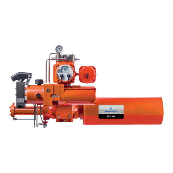
Summary of Contents for Emerson Bettis WO
- Page 1 Installation, Operation and Maintenance Manual MAN-02-10-92-0705-EN Rev. 0 March 2019 WO & WB AWWA Gears & MG Power Gears Instruction & Maintenance Manual...
-
Page 3: Table Of Contents
Installation, Operation and Maintenance Manual Table of Contents MAN-02-10-92-0705-EN Rev. 0 March 2019 Table of Contents Section 1: Purpose Section 2: Lubrication Lubrication Grease Specification ..............2 Section 3: Installation Procedure General Instructions ..................3 Stop Setting Procedure .................. 3 Section 4: Disassembly Instructions Instructions - WO &... -
Page 4: Section 1: Purpose
Section 1: Lubrication Installation, Operation and Maintenance Manual March 2019 MAN-02-10-92-0705-EN Rev. 0 Section 1: Purpose This instruction and maintenance manual replaces document W291 and explains how to install, operate, and maintain the WO, WB & MG Gears. WARNING: Read this manual in its entirely before installing, operating, or performing maintenance on the WO, WB &... -
Page 5: Section 2: Lubrication
Installation, Operation and Maintenance Manual Section 2: Installation Procedure MAN-02-10-92-0705-EN Rev. 0 March 2019 Section 2: Lubrication Lubrication Grease Specification Extreme pressure multipurpose grease, NLGI Grade EP-0, suitable for bronze gear assemblies. Inspection Procedure: 1. Ensure the worm is immersed in lubricant. Lubrication should be checked periodically to determine its condition. -
Page 6: Section 3: Installation Procedure
Section 3: Disassembly Instructions Installation, Operation and Maintenance Manual March 2019 MAN-02-10-92-0705-EN Rev. 0 Section 3: Installation Procedure General Instructions Refer to Figure 1. 1. Place valve in full closed position. 2. Install splined bushing (17) on valve shaft (and key). Tighten set screw (20) to secure bushing to shaft. -
Page 7: Section 4: Disassembly Instructions
Installation, Operation and Maintenance Manual Section 3: Disassembly Instructions MAN-02-10-92-0705-EN Rev. 0 March 2019 Section 4: Disassembly Instructions Instructions - WO & WB AWWA Gears Refer to Figure 1. 1. Remove hex head cap screws (12) and seal washers (15). 2. - Page 8 Section 3: Disassembly Instructions Installation, Operation and Maintenance Manual March 2019 MAN-02-10-92-0705-EN Rev. 0 Figure 1 Assembly WO20 67:1 6.50" (DWG 84216 Rev. F) 16.5 ft-lb 16.5 ft-lb 21 10 16.5 ft-lb 84216-B WO20-B 67:1 6.50" (CW for CW) Assembly Notes: ITEM CODE PART NUMBER DESCRIPTION...
-
Page 9: Instructions - Gb1 Spur Gear Attachment
Installation, Operation and Maintenance Manual Section 3: Disassembly Instructions MAN-02-10-92-0705-EN Rev. 0 March 2019 Instructions - GB1 Spur Gear Attachment 1. Remove retaining ring (32), allowing the removal of handwheel and key (33) from input shaft (30). 2. Remove eight GB1 cover bolts (29), housing cover (27) and gasket (24). 3. -
Page 10: Instructions - Gb3 Spur Gear Attachment
Section 3: Disassembly Instructions Installation, Operation and Maintenance Manual March 2019 MAN-02-10-92-0705-EN Rev. 0 Instructions - GB3 Spur Gear Attachment 1. Remove retaining ring (34), allowing the removal of handwheel and key (32) from input shaft (33). Note: Key (33) not used for tandem mount GB 1 /G83. Input shaft (33) is splined. -
Page 11: Instructions - Mg Quarter Turn Power Assemblies
Installation, Operation and Maintenance Manual Section 3: Disassembly Instructions MAN-02-10-92-0705-EN Rev. 0 March 2019 Instructions - MG Quarter Turn Power Assemblies 1. Separate "M" electric unit (DWG 83775) from MG Power Assembly by removing bolts (23) and pulling the two assemblies apart. 2. -
Page 12: Appendix A: Reference Drawings
Appendix Installation, Operation and Maintenance Manual March 2019 MAN-02-10-92-0705-EN Rev. 0 Appendix: A Reference Drawings 16.5 ft-lb 16.5 ft-lb 21 10 16.5 ft-lb 84216-B WO20-B 67:1 6.50" (CW for CW) Assembly Notes: ITEM CODE PART NUMBER DESCRIPTION 1) Customer furnished mounting screws should be DI END CAP 35333 CI03... - Page 13 Installation, Operation and Maintenance Manual Appendix MAN-02-10-92-0705-EN Rev. 0 March 2019 ERO 20367 Copyright 2018, Emerson Process Management Valve Automation, Inc., All Rights Reserved. DESCRIPTION Assembly Type M (Ductile) Basic Drawing PAGE NUMBER 83775-(D) 1 of 2 ORIG DATE APRD...
- Page 14 Appendix Installation, Operation and Maintenance Manual March 2019 MAN-02-10-92-0705-EN Rev. 0 ERO 20367 Copyright 2018, Emerson Process Management Valve Automation, Inc., All Rights Reserved. DESCRIPTION Assembly Type M (Ductile) Basic Drawing PAGE NUMBER 83775-(D) 2 of 2 ORIG DATE APRD...
- Page 15 Installation, Operation and Maintenance Manual Appendix MAN-02-10-92-0705-EN Rev. 0 March 2019 Appendix...
- Page 16 Appendix Installation, Operation and Maintenance Manual March 2019 MAN-02-10-92-0705-EN Rev. 0 Appendix...
- Page 18 Tianjin 301700 Holland Fasor 6 P. R. China Székesfehérvár 8000 The Emerson logo is a trademark and service mark of Emerson Electric Co. T +86 22 8212 3300 Hungary Bettis is a mark of one of the Emerson family of companies.


