Table of Contents
Quick Links
System Manager(Server Software)
Audio Interface Unit
Audio Interface Unit
Network Module
IP Remote Microphone
Thank you for purchasing TOA's Network PA system.
Please carefully follow the instructions in this manual to ensure long, trouble-free use of your
equipment.
OPERATION INSTRUCTIONS
Network PA System
IP-3000SM
IP-3010AF
IP-3001AF
IP-300XI
IP-300RM
Table of Contents

Related Manuals for Toa IP-3000SM


Summary of Contents for Toa IP-3000SM
- Page 1 IP-3000SM Audio Interface Unit IP-3010AF Audio Interface Unit IP-3001AF Network Module IP-300XI IP Remote Microphone IP-300RM Thank you for purchasing TOA's Network PA system. Please carefully follow the instructions in this manual to ensure long, trouble-free use of your equipment.
-
Page 2: Table Of Contents
Table of Contents About the Software License ······································································ 6 ··············································· 6 Individual Information on Open-Source Software Chapter 1: System Summary 1. General Description ······································································· 8 2. Features ························································································· 8 3. Caution ·························································································· 8 4. System Configuration ····································································· 9 5. Nomenclature and Functions ·······················································... - Page 3 5. Setting Up the IP-3000SM System Manager ································ 31 System Requirements ······································································ 31 Installation ······················································································ 31 6. Setup Flow Procedure ·································································· 32 Chapter 3: Functions and Operation 1. Broadcasting Function ·································································· 34 Types of Broadcast ·········································································· 34 Explanation of Settings ···································································· 34 Broadcasts Initiated by Contact Activation ············································...
- Page 4 List of Connected Equipment ····························································· 72 Surveillance ····················································································· 73 System Log ······················································································ 74 5. Specifications ··············································································· 75 IP-3000SM System Manager ····························································· 75 IP-3010AF I/O Interface ···································································· 76 IP-3001AF Interface ········································································· 77 IP-300XI Module ·············································································· 78 IP-300RM Remote Microphone ··························································· 79 Chapter 4: System Settings 1.
- Page 5 Selection Item and Contents ····························································· 96 Zone Pattern Settings ····································································· 97 Setting Method ·············································································· 97 Contact Output Pattern Settings ························································· 98 Setting Method ·············································································· 98 Contact Device Setup ······································································· 99 Setting Method ·············································································· 99 Microphone Settings ······································································ 100 Setting Method ············································································ 101 Contact Microphone Settings ···························································...
-
Page 6: About The Software License
For Specific Open-Source Software Information Please contact your nearest TOA sales office if you require details about any of the open- source software incorporated within the products in this system. However, we are unable to respond to inquiries about the contents of the open source. -
Page 7: Chapter 1: System Summary
CHAPTER 1: SYSTEM SUMMARY – 7 –... -
Page 8: General Description
1. GENERAL DESCRIPTION ● The IP3000 system is a multi-source general broadcast system that utilizes an IP network. It is comprised of a PC server (which hosts the System Manager), an input and output interface, and a remote microphone. ● Web browser–based access to the System Manager PC allows system setting, status monitoring, and device control. -
Page 9: System Configuration
3. SYSTEM CONFIGURATION Server system] ・Network PA system Manager ptional. *The server itself is o IP-3010AF [Audio Input and Output System] Sound source ・Network PA I/O Interface IP-3010AF Amplifier [User Operation] ・Network PA Remote IP-300RM Microphone ・Web Viewer Web viewer –... -
Page 10: Nomenclature And Functions
4. NOMENCLATURE AND FUNCTIONS IP-3010AF Audio Interface Front Panel 1. Power Indicator [POWER] (Green) Lights when the power is turned on. 2. MAC Address The unit’s MAC address (a 12-digit alphanumeric character string separated by hyphens.) 3. LINK/ACT Indicator (Green) Lights when the unit is connected to a network. - Page 11 Rear Panel 9. Functional Ground Terminal [SIGNAL GND] Be sure to ground this terminal. NOTE: This terminal is not a safety ground. 10. DC Power Input Terminal [DC INPUT] Connect the 24V DC power to this terminal. 11. AC Adapter Input Terminal [DC INPUT] Connect the optional AD-246 AC Adapter to this terminal.
-
Page 12: Ip-3001Af Interface
IP-3001AF Audio Interface Front Panel 1.Control input [C-IN] Non-voltage contact input, open voltage: DC24V, short-circuit current: below 5mA. 2.Audio input [AUDIO INPUT] Electronically balanced input, input impedance 2.2kΩ, MIC -60dB*1/LINE 0dB*1 switchable input selections. 3.Audio output [AUDIO OUTPUT] Electronically balanced output, 0dB*1, 10kΩ 4.Control output [C-OUT] Relay control contact output, contact withstand voltage: DC 24V, maximum current: 500mA. - Page 13 Side Panel 1.Input level switch [MIC/LINE] MIC -60dB *1/LINE 0dB*1, input impedance 2.2k. 2.Phantom power switch [PHANTOM] Phantom voltage DC17V. 3.Signal grounding (SIGNAL GND) Grounding is required. Note: this is not for protective earth. Note: the switches above shall be operated when the unit is disconnected from its power source;...
-
Page 14: Ip-300Xi Module
IP-300XI Network Module Front Panel 1.Network connection port [LAN] It can be connected with 100 BASE-T network cables. 2.Reset switch [RESET] Press this button to reset the module. 3.Status indicator [STATUS] The green indicator will flicker regularly when the module is normal. 4.Input volume control [VOLUME] Adjusts gain of the input Note:... -
Page 15: Ip-300Rm Remote Microphone
IP-300RM IP Remote Microphone Top Panel 1. Microphone Used for making microphone announcements. 2. Power Indicator [POWER] (Green) Lights when the power is turned ON. 3. Failure Indicator (Red) Continuously lights, flashes or distinguishes in interlock with the function operation status set during system settings. 4. - Page 16 Side Panel 10. Microphone Input Level Control [MIC] Adjusts the microphone (1) volume. The volume increases as the control is rotated clockwise, and decreases as the control is rotated counterclockwise. 11. Speaker Output Level Control [SP] Adjusts the speaker (20) output volume. The volume increases as the control is rotated clockwise, and decreases as the control is rotated counterclockwise.
-
Page 17: Chapter 2: Installation And Connections
CHAPTER 2: INSTALLATION AND CONNECTIONS – 17 –... -
Page 18: Rack-Mounting The Ip-3010 Interface
The rack mounting screws are not supplied with the interface. Prepare the appropriate screws* separately. Use of incorrect screws could result in fire, damage or personal injury. *Prepare 5×12 tapping screws with plain washers when mounting in a TOA equipment rack. – 18 –... -
Page 19: Installation Ip-3001Af Interface
2. INSTALLATION IP-3001AF Interface Wall mounting By using additionally procured MB-15B connecting fittings, the unit may be wall- mounted. Step 1: Use the M3x8 screws provided along with the unit to fix the MB-15B connecting fittings on both sides of the unit. Step 2: Provide installation screws with proper sizes for wall-mounting based on the actual installation environment to fix the unit onto the wall. -
Page 20: Power Cord Fastener Installation
Power cord fastener installation Use a power cord fastener to prevent fall of the power plug due to gravity of the adapter. Step 1: Wind the adapter wire on the power cord fastener. Step 2: Use the M3 x 6 screws provided along with the unit to fix the power cord on the side of the unit. -
Page 21: Connections
3. CONNECTIONS IP-3010AF Network PA I/O Interface Power Connections [When using the 24V DC power supply] Connect the 24V DC power supply to the interface’s DC power input terminal (DC INPUT). NOTE: Use a DC power supply with a rated output current exceeding 1A. -
Page 22: Terminal Connections
Terminal Connections Network connections For this connection, use Category 5 or greater UTP straight cable with an RJ-45 connector. NOTE: Connect this terminal to a network component capable of full-duplex communication. → To network Audio I/O terminal connections For wiring of the connectors attached to the audio I/O terminals, please refer to Page 2-6 “Detachable Terminal Plug Connections.”... - Page 23 Control I/O terminal connections Connect the control output terminal of this interface to another interface’s control input terminal, and the former’s control input terminal to the latter’s control output terminal using two control wires for each connection. NOTE: Be sure to connect only the control wires from this interface to the other interface’s control input terminals.
-
Page 24: Detachable Terminal Plug Connections
Detachable Terminal Plug Connections 1. Connect wires to the detachable terminal plug. [Recommended regular screwdriver] 1-1.Loosen terminal screws and insert wires. 1-2.Fasten the terminal screws securely. Ensure that the wires do not separate from the plug by pulling them. If they come free, loosen the terminal screws and repeat these steps again. -
Page 25: Audio Input/Output Signal Terminal Wiring Method
IP-3001AF Interface Audio Input/Output Signal Terminal Wiring Method Detachable Terminal Plug Connections – 25 –... -
Page 26: Settings
IP-300XI Module Settings Note AX-0120/0240,FS-9250DA and DA-520H are products sold only for regions. – 26 –... -
Page 27: Module Installation
Module Installation Applicable Number of Modules to Different Products Note AX-0120/0240, FS-9250DA and DA-520H are products sold only for regions. – 27 –... -
Page 28: Ip300Rm Network Pa Remote Microphone
IP300RM Network PA Remote Microphone [Caution] When using an AC adapter, use the optional AD-246 Adapter. Use of an AC adapter other than the AD-246 could cause fire or other damage. (1) Functional ground connection NOTE: Be sure to connect the IP-300RM’s functional ground terminal. (2) Control input terminal connection [Wire to use] Conductor diameter: ø0.4 –... -
Page 29: Remote Microphone Display Label Attachment
4. REMOTE MICROPHONE DISPLAY LABEL ATTACHMENT Attaching and removing display labels Insert a display label cut to the specified size into the label insertion slot. To remove the label, extract it from the label slot using a pointed object. – 29 –... -
Page 30: Creating Display Labels
Creating Display Labels Create a display label: (1) By hand: Copy the following “Label Dimensional Diagram” to a piece of paper of 0.2mm in thickness or less, write the display contents on it, then cut out the label along the dotted lines. -
Page 31: Setting Up The Ip-3000Sm System Manager
5. SETTING UP THE IP-3000SM SYSTEM MANAGER System Requirements < System Manager PC > Hardware Requirements; CPU: Intel Core i3-4130 or greater Memory: 8GB or more Display: 1028 × 768 resolution or higher Hard disk drive: 100GB or more free space available (for installation) -
Page 32: Setup Flow Procedure
6. SETUP FLOW PROCEDURE The procedure for setting the network PA system is as follows: 1. Before performing system settings System and equipment settings are required before the network PA system can be operated, Use a web browser to perform settings. All system setting contents are saved to the System Manager. -
Page 33: Chapter 3: Functions And Operation
CHAPTER 3. FUNCTIONS AND OPERATION – 33 –... -
Page 34: Broadcasting Function
1. BROADCASTING FUNCTIONS Types of Broadcast Broadcasts over network PA systems are made according to the settings for classification, priority degree, fade-in/fade-out (FI/FO) time and ducker. Each setting is performed for individual audio input channels in the system’s Equipment settings. For details, please refer to Chapter 4, System Settings. Explanation of Settings [Classification] There are 3 classifications: BGM, general-purpose and emergency. -
Page 35: Broadcasts Initiated By Contact Activation
Broadcasts Initiated by Contact Activation The I/O (input & output) interface’s control input is used for these broadcasts. Broadcasts continue as long as the interface’s contact input is at make. Both audio and control signals are inputted to the I/O interface from each connected input, such as from a microphone or audio file, and if the control signal is ON (make status), the broadcast is initiated. -
Page 36: Broadcasts From The Ip-300Rm Remote Microphone
Functions assignable to function keys and control input terminals Any of the functions shown in the table below can be assigned to the remote microphone’s individual function keys and the control input terminal shown above. Assign each function in the Contact Microphone settings portion of the System settings. -
Page 37: Functions Assignable To Each Status Indicator
Functions assignable to each status indicator Any of the functions shown in the table below can be assigned to the remote microphone’s individual status indicators shown above. Assign each function in the Contact Microphone settings portion of the System Settings. For details, please refer to Chapter 4, System settings. - Page 38 Assignable Function Description of Function Status Display Contents Recording playback Continuously lights during playback of No playback of status recorded microphone broadcast. recording. Recording playback in progress. Monitor selection Continuously lights during playback No playback of monitor status of monitor input from the monitor input.
-
Page 39: Operation
Operation The following functions can be enabled by way of the function keys: microphone broadcast, external input broadcast, emergency microphone broadcast, recording playback broadcast, start and end of pattern activated broadcast, and monitor selection. Further, each status indicator displays the status of its corresponding function. Here, operation examples are explained based on the following function key and status indicator setting examples. - Page 40 Status Indicator 13 (Chime) flashes while the chime is sounding. When the chime ends, Status Indicator 13 (Chime) lights and microphone broadcasting can begin. 4. Terminate microphone broadcast. Press the Talk key again to terminate the microphone broadcast. If the chime function has been enabled, a chime tone (descending 4-note tone) sounds.
- Page 41 4. Terminate emergency microphone broadcasts. Press the Emergency key again to terminate the emergency microphone broadcast. If the chime function has been enabled, a chime tone (descending 4- note tone) will also sound. In this event, the chime tone can be heard from the IP-300RM unit’s built-in speaker.
- Page 42 3. Confirm the recorded contents. Pressing Function Key 12 causes the recorded contents to be played back from the IP-300RM unit’s built-in speaker. Status Indicator 12 continuously lights during playback of recorded contents. 4. Terminate the confirmation of the recorded contents. Pressing Function Key 12 again terminates playback.
-
Page 43: Broadcasts By Microphone Console
Broadcasts by Microphone Console Make broadcasts from the Web Viewer’s microphone console. By selecting and operating the buttons on the screen, functions similar to those available on the IR-300RM Remote Microphone can be realized. A single console can be set for each login user. Perform settings in the User settings portion of the System settings. - Page 44 [Microphone Console Screen Example] Chime Using the corresponding buttons, microphone broadcasts, external input broadcasts, emergency microphone broadcasts, recording playback broadcasts, activation/deactivation of pattern activated broadcasts, and monitor selection can all be enabled. Equipment function status can also be confirmed by way of each button’s display color.
-
Page 45: Operation
Display Section] The display appears as follows if the recording function has been enabled on the Microphone Console setting screen: Display Function Lights red when the input level of the audio input channel set on the (1) Peak Indicator microphone console screen exceeds +8 dB. Lights green when the input level of the audio input channel set on the (2) Signal Indicator microphone console screen exceeds −40 dB. - Page 46 When chime play ends, the color of the ‘Chime’ button changes to indicate that the destination selection is in progress, allowing the microphone broadcast to begin. 4. Terminating microphone broadcasts. Clicking the ‘Microphone’ button again terminates the microphone broadcast. If the chime function has been enabled, a chime tone (descending 4-note tone) is broadcast, which can be heard from the IP-3010AF interface’s connected monitor speaker.
- Page 47 3. Starting emergency microphone broadcast. If the ‘Emergency Microphone’ button is clicked, its color changes to indicate that the broadcast is in progress and the emergency microphone broadcast is started. If the chime is enabled, a chime tone (ascending 4-note tone) is broadcast, which can be heard from the monitor speaker connected to and set for the IP- 3010AF interface.
- Page 48 2. Terminating monitor input broadcast. Clicking the ‘Monitor 1’ button again terminate the playback of the monitor input. If terminated, the ‘Monitor 1’ button’s color returns to its original color. NOTE: Monitors are selected alternatively. When switching the monitor input, terminate the monitor input currently played back first.
- Page 49 7. Terminating the broadcast of the recorded contents. If playback of the entire recorded contents is finished, the broadcast is terminated. If the chime is enabled, a chime tone (descending 4-note tone) is broadcast, which can be heard through the speaker set for the IP-3010AF interface.
-
Page 50: Audio Monitor
Audio Monitor Voice announcements being transmitted to the broadcasting destination can be monitored using the monitor speaker. To initiate monitoring, use the speaker connected to the IP-3010AF Interface’s audio output or the IP-300RM Remote Microphone’s built-in speaker. The following settings and connections are required in order to use this function: Perform a feedback connection of the voice output being transmitted to the target broadcasting destination with the IP-3010AF’s audio input. -
Page 51: Audio I/O Adjustment Functions
2. AUDIO I/O ADJUSTMENT The sound volume and sound quality of the IP-3010AF’s audio I/O channels can be adjusted on the Audio screen. The sound volume and sound quality of the IP- 300RM’s microphone input, external input and monitor speaker external output can also all be adjusted. -
Page 52: Audio I/O Level Indication
Screen Description Audio I/O selection Selects either audio input or output [Audio Input] Displays TRIM, EQ and COMP setting screens. Item selection button [Audio Output] Displays EQ, COMP and DELAY setting screens. Level indication Indicates the input level in numerical values. Indicates the input level by means of a meter. -
Page 53: Saving Audio I/O Parameters
Saving Audio I/O Parameters Each audio I/O parameter is saved to a selected Audio scene. When saving to other Audio scenes, set and save each parameter after switching to the Audio scene to which the parameter will be saved. Switching the Audio scene Click the Audio scene selection button located at the upper left of the screen to select the Audio scene to be set from the dropdown list. -
Page 54: Trim Settings
Trim Settings Trim can only be set for audio input channels. Clicking the Trim button displays the Trim screen. Fader ON/OFF Button Setting method Set the trim with the fader, and enable or disable the setting using the ON/OFF button. After setting is complete, click the ‘Save’... -
Page 55: Eq Settings
EQ Settings Set the equalization for each channel. Clicking the ‘EQ’ button displays the EQ screen. EQ curves are displayed in the upper part of the screen, depending on parameter settings. ON/OFF button Setting parameters, contents and range are as follows Parameter Setting Contents Setting Range... -
Page 56: Comp Settings
Comp Settings Set the compression for each channel. Clicking the “COMP” button displays the COMP screen. COMP curves are displayed on the upper part of the screen, reflecting parameter settings. Threshold level indicator ON/OFF button Adjustable parameters and setting ranges are as follows Parameter Setting Range Threshold (dB) -
Page 57: Threshold Level Indicator
Threshold Level Indicator Indicates the difference between the set threshold level and the actual input level. When the input to set threshold level is −6 dB ~ 0 dB: The [▷] indicator lights green. When the input to set threshold level is −3 dB ~ +3 dB: The [○] indicator lights green. When the input to set threshold level is 0 dB ~ +6 dB: The [◁] indicator lights green. -
Page 58: Audio Scene Display, Switching And Name Change
Audio Scene Display, Switching and Name Change Display of the Audio Scene in Operation Which Audio scene the system is currently operating on is displayed on the Audio Scene indicator located at the lower left of the full screen. Audio Scene indicator Audio Scene Switching There are two different methods for switching Audio scenes. -
Page 59: Timer Functions
3. TIMER FUNCTIONS Descriptions of Terms Term Description Event A single unit of operation performed by timer control. (Example: Morning broadcast of radio exercise program.) Pattern A single unit into which multiple events are combined. A single pattern needs to be set per day. -
Page 60: Timer Function Setting Flow
-
Page 61: Pattern Settings
Pattern Settings Set the events for a pattern according to the following procedures: 1. Select Home Screen → Timer settings → Pattern settings or Header menu → Timer settings → Pattern settings on the Web Viewer. The Pattern Setting screen is displayed. Header Menu Event List ▼... - Page 62 4. Set an event. When adding a new event: Clicking the ‘Add’ button displays the event editing box on the right side of the screen. Enter the contents for the event setting item. The following items can be selected for the event setting item: Event Setting Item Description Event Settings...
-
Page 63: Copy Of The Pattern
Copy of the pattern It is possible to copy and edit patterns. Select ‘▼’ for the pattern of the copy source from the pattern list and click the ‘Copy’ button, then select ‘▼’ for the pattern of the copy destination and click the “Paste” button. -
Page 64: Calendar Settings
Calendar Settings Assign set patters to the weekly and yearly programs. In the weekly program settings, set a basic weekly pattern. In the yearly program settings, set two years’ program after the current month. 1. Select ‘Home Screen’ → ‘Timer settings’ → ‘Calendar settings’ or ‘Header menu’ →... -
Page 65: Week's Starting Day
Reflect the weekly program in the yearly program. 3-1. Click the period designation field on the Weekly Pattern box to designate the period. Designate the period on the calendar that appears if the period designation field is clicked. Period Entry Field [Period Entry Field] 3-2. -
Page 66: Broadcast Advance Notice And The Day's Pattern Display
Broadcast Advance Notice and the Day’s Pattern Display Broadcast Advance Notice Display This function displays the contents which are to be broadcast next. The button of the event name to be broadcast next is displayed on the “Next broadcast schedule” box located on the lower part of the screen. When the event name button is clicked, the details of the event are displayed. -
Page 67: Monitor Function
4. MONITOR FUNCTION Viewer It is possible to display the broadcast status or control broadcasts on a map. Map display settings are performed on the ‘Map display settings’ screen and ‘Map page settings’ screen in System Settings. For details, please refer to Chapter 4, System Settings. - Page 68 Status Display on the Map Page Clicking a Map Page button on the Map screen displays its corresponding map page. If the set event occurs on the Map page, a related icon and shape are displayed. For details, please refer to Chapter 4, System Settings. –...
-
Page 69: System Status
System Status Audio I/O Status Display System broadcasting status can be quickly checked. Display of the audio I/O status screen Click either ‘System status’ → ‘Audio I/O status’ on the home screen or ‘System status’ → ‘Audio I/O status’ from the header menu. The Audio I/O Status screen appears. -
Page 70: Contact I/O Status
Contact I/O Status It is possible to quickly confirm the contact I/O status of the IP-3010AF interface and the status of each key and status indicator of the IP-300RM remote microphone connected to the system. Displaying the Contact I/O Status Screen Click either ‘System status’... -
Page 71: The Ip-300Rm's Status Display
The IP-300RM’s status display Shown below is the correspondence of the IP-300RM’s individual key/terminal/indicator to the on-screen number: [Contact Input] [Contact Output] Indicator Function key 1 Status indicator 1 Function key 2 Status indicator 2 Function key 3 Status indicator 3 Function key 4 Status indicator 4 Function key 5... -
Page 72: List Of Connected Equipment
List of Connected Equipment The communication status of all equipment connected to the system is displayed in list form. Display of the Connected Equipment List Screen Click either ‘System status’ → ‘Connected Equipment List’ on the home screen or ‘System status’... -
Page 73: Surveillance
Surveillance This function displays the failure status the system detects. To enable this function, perform settings by selecting System Settings → ‘Surveillance settings’ screen. Surveillance screen display Click ‘Surveillance’ on the home screen or click ‘Surveillance’ from the header menu. The Surveillance screen is displayed. -
Page 74: System Log
System Log System operation log can be confirmed in real time. System log display Click ‘System log’ on the home screen or click ‘System log’ from the header menu. The System Log screen is displayed. When the System Log screen is displayed, the day’s log is displayed from top to bottom in chronological order from the latest log. -
Page 75: Specifications
5. SPECIFICATIONS IP-3000SM System Manager (Sever Software) Control Object Model Network PA System I/O interface IP-3010AF I/O interface IP-3001AF I/O module IP-300XI Remote microphone IP-300RM Max. Connectable No I/O interface IP-3010AF: AA pieces I/O interface IP-3001AF: BB pieces I/O module IP-300XI: CC pieces... -
Page 76: Ip-3010Af I/O Interface
IP-3010AF Audio Interface Power Supply 24V DC (supplied from an optional AC adapter or 2P detachable terminal block) Current Consumption 1A or less Audio Input Microphone/Line: 4 monaural channels, −60 dB*/0 dB* (switchable, adjustable with volume control), input impedance 2.2k Ω, balanced, phantom power 17V (ON/OFF switchable), detachable terminal block (3P) Audio Output Line: 4 monaural channels, 0 dB*, 10k Ω, balanced, detachable terminal block... -
Page 77: Ip-3001Af Interface
IP-3001AF Audio Interface Power Supply IEEE802.3af standard power supply device or DC 24V power supply Current Consumption 2.2W or less Audio Input Electronically balanced input, phantom voltage DC17, MIC -60dB /LINE 0dB , detachable terminal block (10P) Audio Output Electronically balanced output, 0dB , detachable terminal block (10P) Frequency Characteristics... -
Page 78: Ip-300Xi Module
IP-300X1 Network Module Power Supply DC 24V supplied by the power amplifier body Current Consumption 70mA or less Sampling Frequency 48 kHz Quantization Bit No 16 bits Network Network I/F: 100BASE-T, 1 port Network protocol: TCP, UDP, ARP, RTP, ICMP, HTTP, IGMP and FTP Switch Reset switch in the front Indicator... -
Page 79: Ip-300Rm Remote Microphone
IP-300RM IP Remote Microphone Power Supply 24V DC (supplied from an optional AC adapter or 2P detachable terminal block) Current Consumption 500mA or less External Audio Input Line: 1 monaural channel, −20 dB*, 10k Ω, unbalanced, ø3.5mm stereo mini jack External Audio Output Line:1 monaural channel, 0 dB*, 600 Ω, unbalanced, ø3.5mm stereo mini jack Frequency Characteristics... -
Page 80: Chapter 4: System Settings
CHAPTER 4. SYSTEM SETTINGS – 80 –... -
Page 81: Starting The Web Viewer
1. STARTING THE WEB VIEWER Login Screen This screen first appears on the System Manager PC’s web browser when a connection is made. Explanation of the screen User ID entry field Password entry field Login button How to Log in 1. -
Page 82: Home Screen
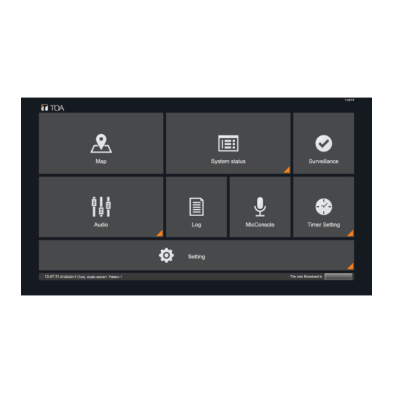
Home Screen This screen first appears when a user logs in to the System Manager PC from a web browser. (When logged in with Administrator authority) (When logged in with Maintenance authority) Screen Explanation (1) Screen selection panel: Selecting a panel causes the screen to change. (2) Logout: Logs out of the screen. -
Page 83: Menu Configuration
2. MENU CONFIGURATION Administrator Authority Shown below is the configuration of pages an Administrator can access. Administrators can access all operations. – 83 –... - Page 84 Basic configuration Device list Device configuration Streaming settings Audio Device setup System Zone Pattern configuration setup Contact Out Pattern Setup Contact device setup Microphone settings Contact microphone settings Contact microphone settings 2 Setting MicConsole settings MicConsole display settings Surveillance settings Voice monitor setting Priority control...
-
Page 85: Maintenance Authority
Maintenance Authority Maintenance Authority is the configuration that results from excluding the ‘System Settings’ from the Administrator’s menu configuration. User Authority Only the microphone console is the screen configuration that a user with User authority can open. Login Screen Microphone Console –... -
Page 86: System Setting Menu
System Setting Menu Category Menu Setting Content System Basic configuration Set all basic information regarding the system settings. configuration Device list Register all components connected to the system and display them in list form. Device configuration Set the purpose of use and operation of each component’s audio channels. -
Page 87: Layout During System Setting
Layout During System Setting The basic setting screen configuration is as follows: Returns to the Home screen ② ① ⑤ ③ ④ Screen Explanation (1) Setting wizard navigation: Displays the list of setting items (2) Header menu (3) ‘Return’ button: Moves to the previous setting item. (4) ‘Next’... -
Page 88: System Configuration
3. SYSTEM CONFIGURATION Basic Settings Set basic information regarding system settings. Item Description Enter an arbitrary project name Project name Data version Enter an arbitrary data version. Creator Enter a creator. Setting Method Enter and save the necessary item. Operation Buttons Cancel: Reverts to the Home screen without saving any setting. -
Page 89: Device List
Device List Components to be connected to the system are registered and displayed in list form. Checkbox Handle Setting Method 1. For equipment connected to the same network as the System Manager, click the ‘Detect Equipment’ button and register on the ‘Detect Equipment’ screen. 2. -
Page 90: Equipment Detection
Equipment Detection This function detects and registers all components connected to the same network as the System Manager. Page Introduction (1) Device been added Added device list (2) Scan (3) Import (4) Scanning list (A) Back (B) Next Settable Items 1. -
Page 91: Device Configuration
Device Configuration Page Introduction (1) Device list (2) System connection (A) Cancel (B) Back (C) Next Settable Items 1. Enter ‘Device advanced Settings’ page Setting Method 1) Click on a device list or any device in the device connection graphics to enter the "Device advanced settings"... -
Page 92: Device Advanced Settings
Device Advance Settings Set the purpose of use and operation of each component’s audio channel. Item Description Audio Input Name Use these items to input each name within the equipment in batches. If the ‘Copy’ button is clicked after a name is entered, consecutive numbers beginning with ‘1’ are Audio Output Name automatically assigned to the end of the name entered. -
Page 93: Setting Method
Setting Method Select equipment from the Equipment List box and perform the following settings: 1. Set the audio input channel. [For IP-3010AF] Set each of Channels 1 – 4. [For IP-300RM] Set each of Channels 3 and 4. (Channels 1 and 2 are not used.) Microphone input is Channel 3 and external input is Channel 4. -
Page 94: Streaming Settings
Streaming Settings Set an equipment group and multicast address when performing multicast audio streaming. The maximum number of audio streaming channels that a single component can handle is 4. When the number of streaming channels exceeds this limit, streaming settings are required. Item Item Description... -
Page 95: Audio Device Setup
Audio Device Setup Perform connection settings between the IP-3010AF interface and the component connected to the IP-3010AF. Item Description Playing Equipment Enter an arbitrary name Component Name Audio Input Select the interface’s audio input channel. Activation Method Select from ‘Binary (pulse),’ ‘Binary (level),’ ‘Direct (pulse)’ and ‘Direct (level).’ Musical Numbers Enter the number of musical pieces Playback Contact... -
Page 96: Selection Item And Contents
Selection Item and Contents Selection Item Contents (Select) Equipment that do not require control. Binary (pulse) Controls the playing equipment that plays back the sound source designated to be played back when its corresponding contact activation input receives a pulse make signal for playback.. -
Page 97: Zone Pattern Settings
Zone Pattern Settings Page Introduction (1) Add (2) Delete (3) Copy (4) Setting list (5) Setting input (6) All (A) Cancel (B) Back (C) Next Settable Items 1. Zone pattern name 2. Zone pattern Setting Method 1) Set some zone to a group. 2) In the setting list on the left side of the page, press "Add"... -
Page 98: Contact Output Pattern Settings
Contact Output Pattern Settings Page Introduction (1) Add (2) Delete (3) Copy (4) Setting list (5) Setting input (6) All (A) Cancel (B) Back (C) Next Settable Items: 1. Control output pattern name 2. Control output pattern Setting Method 1) Set some control output into a group. 2) Click "Add"... -
Page 99: Contact Device Setup
Contact Device Setup Perform settings to allow broadcasting while the equipment’s contact input receives a ‘make’ control signal. Item Description Contact-activate Enter an arbitrary name. equipment name Audio input Select the equipment’s audio input channel. Activation contact input Set the contact inputs to receive a control signal. Broadcasting destination Select the destinations to which a broadcast is made while the activation checkbox... -
Page 100: Microphone Settings
Microphone Settings Set whether to use the microphone as a ‘contact microphone’ or ‘web microphone’ for the equipment’s audio input. Item Description Microphone Name Enter an arbitrary name Microphone Classification Select either ‘Contact’ or ‘Web.’ Contact: Select when using the IP-300RM or the IP-3010AF’s contact input. Web: Select when using the microphone console screen. - Page 101 Contact Microphone Settings Perform settings for using the ‘Contact Microphone.’ For the IP-300RM, use the following screen: Item Description Cancel All Broadcasting SW Contact Set the switch that cancels all broadcasting Destination SW settings destination settings Chime SW settings SW Contact Set the switch that designates whether or not to sound a chime tone SW-LED Contact...
-
Page 102: Contact Microphone Settings
*Lock: Lock type. Key is locked once pressed, allowing announcements to be made. Press the key again to terminate the announcement. Non-lock: PTT type. Announcements can be sent while the key is held down. Releasing the key terminates the announcement Setting Method 1. -
Page 103: Contact Microphone Settings2
Microphone Contact Settings 2 Page Introduction (1) Microphone contact list (2) Switch (A) Cancel (B) Back (C) Next Setting Method (1) Click the switch on the microphone contact graphic to enter the “Switch Function Setting" page – 103 –... -
Page 104: Switch Function Settings
Switch Function Settings Page Introduction (1) Switch list (2) Function (3) Pattern list (A) Back (B) Next Zone selection module Page Introduction (1) ALL (2) Zone pattern select (3) Control output pattern select (4) Setting input list Pattern starting module Page Introduction (1) Audio input select (2) ALL... -
Page 105: Setting Method
Settable Items 1.Switch name 2.Switch function Setting Method 1) Select the specific function for a switch, then the corresponding module will be displayed on the right side. 2) Zone selection module: 2-1. tick the selected zones’ box 2-2. tick the Selected control outputs’ box 3) Pattern starting module: 3-1. -
Page 106: Microphone Console Settings
Microphone Console Settings Perform screen or broadcasting destination settings as necessary when using the microphone as a ‘Web microphone.’ Set the microphone console using this screen. Item Description Data copy Copy source name To copy setting contents, select a microphone name to use as a copy source. -
Page 107: Setting Method
Setting Method 1) Set all the microphones that controlled by MicConsole. 2) Select the microphone in the microphone list on the left. 3) Determine the page layout. 4) Select the edited page. When there is no edited page, click "Add" to create a new page. -
Page 108: Button Selection
Button Selection Setting Method 1) Choose the button selection after the page selection 2) Button can be set as “Zone selection" “Microphone" “Chime" "BGM" “Emergency broadcast“ “Clear selection" “Pattern Starting" or “Voice Monitor" 3) The buttons are displayed in the fixed frame according to different functions. -
Page 109: Button Characteristics
Button Characteristics Setting of shape and color of a button Setting Method 1. When the button is selected, you can set the shape and text color in the left panel. – 109 –... -
Page 110: Zone Selection Button
Zone Selection Button For "Zone selection", "pattern starting”, “BGM”, “Voice monitor" these 4 buttons, other setting are also needed to set apart from button name and shape Page Introduction (1) Select button (2) Input page name (3) Button undisplay selection Page Introduction (1) Broadcast pattern (2) Contact output... -
Page 111: Pattern Starting Button
Pattern Starting Button Page Introduction (1) Pattern setting input (2) Broadcast pattern (3) Contact output destination pattern (4) Save Settable Items 1. Audio device name 2. Song number 3. Broadcast pattern 4. Contact output destination pattern Setting Method 1) Enter “pattern starting button” page from the sub item of "MicConsole Settings". 2) Select a audio device. -
Page 112: Bgm Button
BGM Button Setting Method 1) Select “BGM” in “button selection” page. 2) Select the audio device and song number Voice Monitor Button Setting Method 1) Select “voice monitor” in “button selection” page. 2) Select the audio input(monitor) from the list Frame Setting Button display position (button can be moved by changing the position of each frame) Copy Data Setting... -
Page 113: Micconsole Display Settings
Microphone Console Display Settings Designate the status color of each button on the microphone console screen. Setting Items Set the button internal field and frame colors for the following items: Unselected Selected Part of designated broadcast zones already in use. All designated broadcast zones already in use. -
Page 114: Surveillance Settings
Surveillance Settings Set the contact where the equipment is notified when the System Manager PC or amplifier fails. When set, the failure detection status is displayed on the Surveillance screen. Item Description Server Error Mains Power Voltage Set the IP-3010AF contact input that connects to the external Setting box Failure equipment’s contact output, which will close when a mains power... -
Page 115: Voice Monitor Settings
Voice Monitor Settings Perform Audio Monitor settings. For further information on the Audio Monitor, refer to Chapter 3, ‘Monitor Function.’ Item Description Audio monitor setting name Enter an arbitrary name. Contact input Set the contact input that activates the ‘Audio Monitor.’ Audio input Set the audio input channel to monitor. -
Page 116: Priority Control Settings
Priority Control Settings Set priority operations and broadcast time limits for each broadcast classification. Item Description Lockout* Select either ‘Enable’ or ‘Disable.’ FIFO/LIFO Select either FIFO (first in first out) or LIFO (last in first out). Broadcast Time Limit Set the broadcast time limit. (Unit: sec. No time limit when set to ‘0.’) * If ‘Enable’... -
Page 117: Map Configuration
4. Map Configuration SETTINGS Display Setting Set the status display color of the Map screen. Item Description Detected Error Map Display Set the character color of the map page selection button for the map on Color which detected errors are displayed. Event Icon Set whether or not to display an event icon on the map when an event occurs. -
Page 118: Page Setup
Page Setup Set the operation of the Map screen. When this screen is set, broadcast status can be displayed and broadcast operations can be controlled by event icons on the Map screen. Description Page name input field Page Name Enter an arbitrary name Object list Object Name Input Field Enter an arbitrary name. -
Page 119: Objects Creation (1)
Objects Creation (1) Page Introduction Screen A: Initial status of “Page creation” page (1) Object list Screen B: Initial status of “Object list” (2) Background (3) Object name input field (4) New Screen C: Page edition (5) Drawing tools (6) Stroke color setting ( with palette display) (7) Fill color setting ( with palette display) (8) Object list (9) Objects action category... -
Page 120: Objects Creation (2)
Objects Creation (2) Page Introduction (1) Drawing tools (2) Stroke color setting (with palette display) (3) fill color setting (with palette display) (4) Object list (5) Objects action category (6) Objects action setting (7) Save Settable Items Objects action category ‥ ‥ Choose from the following four options 1. -
Page 121: Objects Creation (3)
Objects Creation (3) Page Introduction Screen A: Image capture (1) Image capture Screen B: Drawing tools (line or geometric shapes) (2) Drawing tool (line thickness) Screen C: Drawing Tools (Text) (3) text input field (4) text size (5) text font (6) italic (7) bold Screen D : Color setting... -
Page 122: Paint Mode & Move Mode
Page Introduction (1)Paint/Move Paint / Move toggle switch Move Mode Method of Operation 1) Using the “Paint mode” for object creation and edition. 2) To change the position of the object on the page, Click “Paint / Move toggle switch” above the object list to switch to Move mode. -
Page 123: Objects Are Visible・Invisible
Page Introduction (1) Switch for objects are visible ・invisible Checkbox Setting Method 1) If check box on the left side of the object name are not ticked, the object are invisible on the screen. 2) In screen A, All check box on the left side of the object name are ticked. All graphics are visible on the screen. -
Page 124: Management
5. MANAGEMENT Email Settings Set up a mail server. Settings must be performed on this screen when transmitting an error notification or system log by Email. Item Description Transmission Source Email Transmission Source Email Address Address User Name Enter a user name to access the mail server. Password Enter the password for access to the mail server. -
Page 125: Error Notification Settings
Error Notification Settings Set the method and contents of notification to be sent when an error is detected. Item Description Error Notification Setting Enter an arbitrary name Settings Input Screen Name Object Select the equipment to which notifications are sent. Equipment Notification Item Select the error notification item to be sent to the... -
Page 126: Setting Method
Setting Method 1. Select the item from the Settings List. Items can be added to the list by clicking on the ‘Add’ button. Selected item can be deleted from the list by clicking on the ‘Delete’ button. 2. Perform Error Notification settings. Selecting an item on the Settings List allows settings to be performed on the right-side screen. -
Page 127: Log Email Settings
Log Email Settings Set the function to transmit the contents of the system log by means of email. This function transmits emails with csv-formatted system logs attached to designated addressees at a specified time. Item Description Setting Name Enter an arbitrary name. Filter Setting Select the classification of the log to be notified. -
Page 128: User Settings
User Settings Set information on users who can log into the system. Item Description User ID Enter the ID for logging into the system. Password Enter the password for logging into the system. Authority Select the authority of the user (Administrator,’ ‘Maintenance’ or ‘User’). Operation Target Microphone Select the microphone to be operated on the Microphone Console screen. -
Page 129: Maintenance Settings
Equipment log storage location and file format — Acquired equipment logs are stored in the following folder of the System Manager PC in order of date. Folder C:¥ProgramData¥TOA¥IP-3000SM¥EquipmentLog Filename Equipment name yyyymmdd.log — Stored equipment logs can be opened using Memopad or another text editor. -
Page 130: Firmware Settings
Firmware Settings Update the equipment’s firmware. Item Description Filename Select the firmware to be updated. Version Enter the current firmware version. Setting Method 1. Press the ‘Select’ button and select the equipment’s firmware (extension .bin) on the file selection screen. The selected filename is displayed in the Filename field. -
Page 131: Importing And Exporting Settings
6. IMPORTING AND EXPORTING SETTINGS Here, perform operations to import and export the setting files. Settings Import/Export Screen Display On the Web viewer, click ‘Home Screen’ → ‘System Settings’ → ‘Setting Import/Export’ or ‘Header Menu’ → ‘System Settings’ → ‘Import/Export.’ Importing and Exporting All System Settings Import When the ‘Import’...