
Related Manuals for Toa IP-3001AF


Summary of Contents for Toa IP-3001AF
- Page 1 INSTRUCTION MANUAL AUDIO INTERFACE UNIT IP-3001AF Thank you for choosing the TOA audio interface unit. Please carefully follow the instructions in this manual to ensure long, trouble-free use of your equipment. TOA Corporation...
-
Page 2: Table Of Contents
TABLE OF CONTENTS 1.GENERAL DESCRIPTION................3 2.NOMENCLATURE AND FUNCTIONS ............3 Front ......................3 Side ......................4 3.NOTICES ..................... 4 4.CONNECTION METHOD OF REMOVABLE TERMINAL PLUG ....5 5.AUDIO INPUT/OUTPUT SIGNAL TERMINAL WIRING METHOD ....5 6.INSTALLATION ................... 6 6.1 Wall mounting ..................6 6.2 Pad installation ................... -
Page 3: General Description
1. GENERAL DESCRIPTION IP-3001AF is a network audio signal conversion processor. It can transform analog audio signals to digital audio signals or transform digital audio signals to analog audio signals for long-distance transmission via local area networks or wide area networks, featuring low signal transmission loss, good anti-jamming capability and simple wiring. -
Page 4: Side
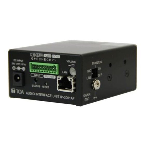
SIDE PHANTOM LINE SIGNAL ① Input level switch [MIC/LINE] MIC -60dB /LINE 0dB , input impedance 2.2kΩ. ② Phantom power switch [PHANTOM] Phantom voltage DC17V. ③ Signal grounding (SIGNAL GND) Grounding is required. Note: this is not for protective earth. Note: the switches above shall be operated when the unit is disconnected from its power source;... -
Page 5: Connection Method Of Removable Terminal Plug
4.CONNECTION METHOD OF REMOVABLE TERMINAL PLUG Notes For audio input and output, shielded lines shall be used. Avoid soldering cable conductor, as contact resistance may increase when the cable is tightened and the solder is crushed, possibly resulting in an excessive rise in joint temperatures. AWG 20~28 wire shall be used. -
Page 6: Installation
6.INSTALLATION 6.1 Wall mounting By using additionally procured MB-15B connecting fittings, the unit may be wall-mounted. Step 1: Use the M3x8 screws provided along with the unit to fix the MB-15B connecting fittings on both sides of the unit. Step 2: Provide installation screws with proper sizes for wall-mounting based on the actual installation environment to fix the unit onto the wall. -
Page 7: Power Cord Fastener Installation
6.3 Power cord fastener installation Use a power cord fastener to prevent fall of the power plug due to gravity of the adapter. Step 1: Wind the adapter wire on the power cord fastener. Step 2: Use the M3 x 6 screws provided along with the unit to fix the power cord on the side of the unit. Step 1: Wind the adapter wire on the power cord fastener. -
Page 8: Dimensional Diagram
VOLUME PHANTOM DC INPUT 0.1A LINE INPUT OUTPUT STATUS RESET SIGNAL AUDIO INTERFACE UNIT IP-3001AF Front view Side view Traceability Information for Europe Manufacturer Authorized representative: TOA Corporation TOA Electronics Europe GmBH 7-2-1, Minatojima-Nakamachi,Chuo-ku,Hyogo,Japan Suederstrasse 282,20537 Hamburg, Germany TOA Corporation...