
Related Manuals for Toshiba MMD-UP0721HP-E1


Summary of Contents for Toshiba MMD-UP0721HP-E1
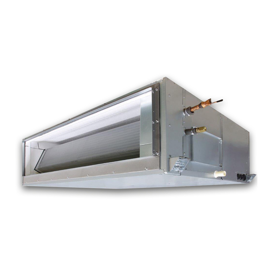
- Page 1 R32 or R410A AIR CONDITIONER (MULTI TYPE) Installation Manual Indoor Unit For commercial use Model name: Concealed Duct High Static Pressure Type English...
-
Page 2: Table Of Contents
For its details, refer by Toshiba Carrier Corporation. He or she has been trained to install, maintain, relocate and remove the air conditioners made by Toshiba Carrier Corporation or, alternatively, he or she has been instructed in such to the “Electrical connection”... - Page 3 Definition of Protective Gear MEANINGS OF SYMBOLS DISPLAYED ON THE UNIT When the air conditioner is to be transported, installed, maintained, repaired or removed, wear protective gloves and ‘safety’ work clothing. This mark is for R32 refrigerant only. In addition to such normal protective gear, wear the protective gear described below when undertaking the special WARNING In case that refrigerant type is R32, this unit uses a flammable refrigerant.
-
Page 4: Precautions For Safety
– 3 – Precautions for safety Warning indications on the air conditioner unit The manufacturer shall not assume any liability for the damage caused by not observing the description of this manual. WARNING WARNING WARNING ELECTRICAL SHOCK HAZARD ELECTRICAL SHOCK HAZARD Disconnect all remote Disconnect all remote electric power supplies before servicing. - Page 5 Only a qualified installer(*1) or qualified service person(*1) is The air conditioner must be transported in stable condition. allowed to undertake work at heights using a stand of 50 cm or If any part of the product is broken, contact the dealer. more or to remove the intake grille of the indoor unit to undertake When the air conditioner must be transported by hand, carry it by work.
- Page 6 – 5 – Installation Tighten the flare nut with a torque wrench in the specified manner. Excessive tighten of the flare nut may cause a crack in Suction duct length must be longer than 850 mm. the flare nut after a long period, which may result in refrigerant When the indoor unit is to be suspended, the designated hanging leakage.
- Page 7 Do not connect earth wires to gas pipes, water pipes, and After the work has finished, use an insulation tester set lightning conductor or telephone earth wires. (500V Megger) to check the resistance is 1M or more between After completing the repair or relocation work, check that the the charge section and the non-charge metal section (Earth section).
-
Page 8: Accessory Parts
– 7 – Accessory parts CAUTION This Air Conditioner has adopted a refrigerant HFC Accessory parts (R32 or R410A) which does not destroy the ozone layer. • As the R32 or R410A refrigerant is easily affected by impurities Part name Q’ty Shape Usage... -
Page 9: Selection Of Installation Place
Installation under high-humidity atmosphere Selection of installation place In some cases including the rainy season, especially inside of the ceiling may become high-humidity atmosphere (dew-point temperature: 23 °C or higher). CAUTION 1. Installation to inside of the ceiling with tiles on the roof Do not install in a location where fl... -
Page 10: Installation
– 9 – Installation space Installation (Unit: mm) Reserve sufficient space required for installation or service work. CAUTION Space required for installation and servicing Strictly comply with the following rules to prevent damage of the indoor units and human injury. Do not put a heavy article on the indoor unit or let a person get on it. - Page 11 Installation of hanging bolt Installation of indoor unit REQUIREMENT Removing the cardboard for transportation Consider the piping / wiring after the unit is hung to Treatment of ceiling determine the location of the indoor unit installation The ceiling differs according to structure of building. Make sure to remove the protection cardboard for transportation that is inserted in the gap between the top and orientation.
-
Page 12: Drain Piping
– 11 – Connecting drain pipe Drain piping Insert exible drain hose into the drain pipe of main unit as far as it will go. Fix it with hose band. CAUTION REQUIREMENT Following the Installation Manual, perform the drain piping work so that water is properly drained. Mount the exible drain hose using the hose band without using adhesive. - Page 13 Heat insulating process As shown in the gure, cover the exible hose and hose band with the attached heat insulator up to the bottom of the indoor unit tightly. Cover the drain pipe tightly with a heat insulator procured locally so that it overlaps with the attached heat insulator of the drain connecting section.
- Page 14 – 13 – Fan characteristics UP072 type UP096 type Standard Air Flow : 3800 (m³/h) Standard Air Flow : 4800 (m³/h) Mid(250Pa) Mid(217Pa) Mid(250Pa) High(250Pa) Mid(183Pa) Mid(217Pa) High(217Pa) Mid(150Pa,117Pa) Mid(183Pa) High(183Pa) Mid(150Pa,117Pa) High(250Pa) High(150Pa) High(217Pa) High(117Pa) High(183Pa) High(83Pa) High(150Pa) High(50Pa) High(117Pa) High(83Pa) High(50Pa)
-
Page 15: Duct Design
Duct design Duct design Arrangement (Unit: mm) Referring to the following dimensions, manufacture duct at the local site. In order to prevent short circuits, design (Thickness of plate : 0.8 mm) the duct work so that the intake and discharge openings are not adjacent to... -
Page 16: Refrigerant Piping
– 15 – Refrigerant piping Tightening connection CAUTION CAUTION Do not burn the pipe heat insulator. Flaring CAUTION Be careful for the flame, due to the brazing Do not apply excessive torque. Otherwise, the Cut the pipe with a pipe cutter. process on the ceiling. -
Page 17: Electrical Connection
Refrigerant amount to be added Heat insulation process Electrical connection For addition of the refrigerant, add refrigerant Apply heat insulation for the pipes separately at liquid “R32 or R410A” referring to the attached side and gas side. Power supply wire and Installation Manual of outdoor unit. -
Page 18
– 17 – Power supply
220V–240V ~, 50 Hz Uv line and Uc line (L2, L3, L4) 0.5 mm² (Up to 500 m) Power supply 208V–230V ~, 60 Hz Wire size : (2-core shield wire, non-polarity) -
Page 19
Remote controller wiring 2-core with non-polarity wire is used for wiring of the remote controller wiring and group remote controllers wiring. Control wiring between indoor units, and outdoor unit (L2, L3) Remote controller wiring, remote controller inter-unit (2-core shield wire, non-polarity) Wire size: 0.5 mm²... - Page 20 – 19 – ■ Wiring between indoor unit and outdoor units NOTE • A wiring diagram below is an example for connection to SMMS-u series. For connecting to other outdoor unit series, refer to the Installation Manual attached to the outdoor unit to be connected. ▼...
- Page 21 Wire connection Remote controller wiring Strip off approx. 9 mm the wire to be connected. REQUIREMENT Wiring diagram Connect the wires matching the terminal numbers. Incorrect connection causes a trouble. Pass the wires through the bushing of wire connection holes of the indoor unit. Keep a margin (Approx.
-
Page 22: Applicable Controls
– 21 – External static pressure Applicable controls Each time [ ] [ ] setting button is settings pushed, indoor unit numbers in the group ■ Applicable controls setup control change cyclically. Select the indoor REQUIREMENT unit to change settings for. (settings at the site) To set the external static pressure, refer to the When the air conditioner is used for the first time, it... -
Page 23
Filter sign setting Remote controller sensor
To set up the external static pressure, use the DIP switch on the circuit board of the wireless reception part. For details, refer to the instruction manual of the wireless remote controller kit. Alternatively, use the switch on the According to the installation condition, the filter sign The temperature sensor of the indoor unit senses indoor micro computer circuit board as shown in the following figure and table. -
Page 24: Test Run
– 23 – Test run Wired remote controller Be sure to stop the air conditioner before making settings. Before test run Execute a test run ■ ■ (Change the setup while the air conditioner is not working.) • Before turning on the power supply, carry out the •... -
Page 25: Maintenance
Maintenance Periodic Maintenance For environmental conservation, it is strongly recommended that the indoor and outdoor units of the air conditioner in use be cleaned and maintained regularly to ensure efficient operation of the air conditioner. When the air conditioner is operated for a long time, periodic maintenance (once a year) is recommended. CAUTION Furthermore, regularly check the outdoor unit for rust and scratches, and remove them or apply rustproof treatment, if necessary. -
Page 26: Troubleshooting
– 25 – Troubleshooting Confirmation and check ■ If a problem occurs with the air conditioner, the OFF timer indicator alternately shows the check code and the indoor Unit No. in which the problem occurred. Check code The indoor Unit No. in which the problem occurred. - Page 27 Check method (The following check code table explain in SMMS-e.) On the wired remote controller, central control remote controller and the interface P.C. board of the outdoor unit (I/F), a check display LCD (Remote controller) or 7-segment display (on the outdoor interface P.C. board) to display the operation is provided.
- Page 28 – 27 – Check code Wireless remote controller Outdoor unit 7-segment display Sensor block display of receiving unit Check code name Judging device Wired remote controller display Auxiliary code Operation Timer Ready Flash 01: TL1 sensor 02: TL2 sensor TL1,TL2 or TL3 sensor trouble 03: TL3 sensor –...
- Page 29 Check code Wireless remote controller Outdoor unit 7-segment display Sensor block display of receiving unit Check code name Judging device Wired remote controller display Auxiliary code Operation Timer Ready Flash Model mismatch of indoor and outdoor unit Detected indoor unit address Indoor unit incompatible with A2L (R32) refrigerant –...
- Page 30 – 29 – Check code Wireless remote controller Outdoor unit 7-segment display Sensor block display of receiving unit Check code name Judging device Wired remote controller display Auxiliary code Operation Timer Ready Flash : Compressor 1 side Outdoor unit fan inverter trouble Inverter : Compressor 2 side : Comp.
-
Page 31: Specifications
Speci cations Declaration of Conformity Sound pressure level (dBA) Manufacturer: Toshiba Carrier (Thailand) Co.,Ltd. Model Weight (kg) Cooling Heating 144 / 9 Moo 5, Bangkadi Industrial Park, Tivanon Road, Tambol Bangkadi, MMD-UP0721HP-E Amphur Muang, Pathumthani 12000, Thailand MMD-UP0961HP-E TCF holder: TOSHIBA CARRIER EUROPE S.A.S... -
Page 32: Appendix
Work instructions 5. When a commercially available dryer is attached to the existing pipes. Manufacturer: Toshiba Carrier (Thailand) Co.,Ltd. The existing R22 and R410A piping can be reused for • There is the possibility that copper green rust has 144 / 9 Moo 5, Bangkadi Industrial Park, Tivanon Road, Tambol Bangkadi, inverter R32 product installations. - Page 33 Warnings on Refrigerant Leakage Existing pipes: Cannot be used. Are there scratches or dents on the existing pipes? Check of concentration limit • Use new pipes. The room in which the air conditioner is to be installed requires a design that in the event of refrigerant gas leaking out, its concentration will not exceed a set limit.
- Page 34 – 33 – Important 2) When there is an effective opening with the adjacent room for ventilation of leaking refrigerant gas (opening without a door, or an opening 0.15 % or larger than the respective floor spaces at the top or bottom of the door).
- Page 35 67-EN 68-EN – 34 –...
- Page 36 144 / 9 Moo 5, Bangkadi Industrial Park, Tivanon Road, Tambol Bangkadi, Amphur Muang, Pathumthani 12000, Thailand 1128950191...