
Related Manuals for Toshiba MMD-UP0031SPHY-E


Summary of Contents for Toshiba MMD-UP0031SPHY-E
-
Page 1
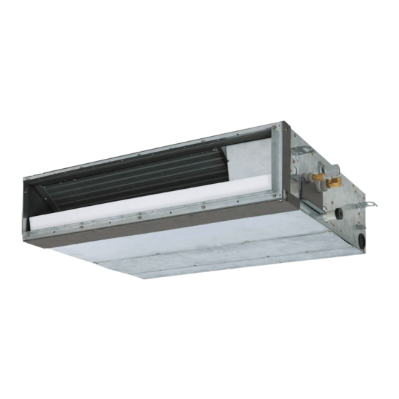
AIR CONDITIONER (MULTI TYPE) Installation Manual Indoor Unit Model name:
MMD-UP0031SPHY-E For commercial use MMD-UP0051SPHY-E MMD-UP0071SPHY-E MMD-UP0091SPHY-E MMD-UP0121SPHY-E MMD-UP0151SPHY-E MMD-UP0181SPHY-E MMD-UP0241SPHY-E MMD-UP0271SPHY-E English... -
Page 2: Table Of Contents
Specifications ............33 work on the air conditioners made by Toshiba Carrier Corporation or, alternatively, he or she has been... - Page 3 Warning Indications on the Air Conditioner Unit Definition of protective gear When the air conditioner is to be transported, installed, maintained, repaired or removed, wear protective gloves and ‘safety’ work clothing. In addition to such normal protective gear, wear the protective gear described below when undertaking the special work detailed in the table below.
-
Page 4: Precautions For Safety
– 3 – Precautions for Safety more or to remove the intake grille of the indoor unit to undertake work. The manufacturer shall not assume any liability for the damage • Wear protective gloves and safety work clothing during installation, caused by not observing the description of this manual. - Page 5 Selection of installation location installed appropriately, a unit may topple over or fall down, causing an accident. • When the air conditioner is installed in a small room, provide • If refrigerant gas has leaked during the installation work, ventilate appropriate measures to ensure that the concentration of the room immediately.
- Page 6 – 5 – • Nitrogen gas must be used for the airtight test. • Under no circumstances, the power supply wire or the indoor and • The charge hose must be connected tightly and in a proper outdoor connecting wire must be connected in the middle manner.
- Page 7 Explanations given to user CAUTION CAUTION • Upon completion of the installation work, tell the user where the R410A refrigerant air conditioner installation circuit breaker is located. If the user does not know where the • This air conditioner adopts the HFC refrigerant (R410A) which circuit breaker is, he or she will not be able to turn it off in the event does not destroy ozone layer.
-
Page 8: Accessory Parts
– 7 – Accessory parts Selection of installation place Avoid installing in the following places Q’ty Select a location for the indoor unit where the cool or warm air will circulate evenly. Part name Model type Shape Usage Avoid installation in the following kinds of locations. 003-012 015-018 024-027... -
Page 9
Installation under high-humidity atmosphere
In some cases including the rainy season, especially inside of the ceiling may become high-humidity atmosphere (dew-point temperature: 23 °C or higher). Air inlet 1. Installation to inside of the ceiling with tiles on the roof 2. -
Page 10: Installation
– 9 – Installation CAUTION CAUTION Strictly comply with the following rules to prevent damage of the indoor units and human injury. • Do not put a heavy article on the indoor unit or let a person get on it. (Even units are packaged) •... - Page 11 Installation of hanging bolt Installation of indoor unit REQUIREMENT • Consider the piping / wiring after the unit is hung to Treatment of ceiling determine the location of the indoor unit installation • Hang the unit in a horizontal position. When unit is hanged to slant, it may cause overflow of drainage. The ceiling differs according to structure of building.
-
Page 12: Drain Piping
– 11 – Drain piping Installation of remote Wireless remote controller controller (sold separately) (sold separately) CAUTION CAUTION For installation of the wired remote controller, follow the The signal receiving unit of indoor unit can receive a Installation Manual attached with the remote controller. signal by distance within approx. - Page 13 Pipe material, size and insulator Drain up The following materials for piping work and insulating process are procured locally. When a down-gradient cannot be secured for the drain pipe, drain-up For drain pipes that will be piping is possible. connected after setup, make a Pipe material Hard vinyl chloride pipe VP25 (Nominal outer diameter 32 mm)
- Page 14 – 13 – Heat insulating process • As shown in the figure, cover the flexible hose and hose band with the attached heat insulator up to the bottom of the indoor unit without gap. • Cover the drain pipe seamlessly with a heat insulator locally procured so that it overlaps with the attached heat insulator of the drain connecting section.
-
Page 15: Duct Design
Duct design Arrangement Referring to the following dimensions, manufacture duct at the local site. (Unit: mm) UP003, UP005, UP007, UP009, UP012 UP015, UP018 UP024, UP027... - Page 16 – 15 – Fan characteristics 003 type 005 type Standard air volume: 410 (m Standard air volume: 450 (m Upper limit of external Upper limit of external static pressure (50Pa) static pressure (50Pa) High (50Pa) High (50Pa) Lower limit of Lower limit of external external static Low (50Pa)
- Page 17 Fan characteristics 015 type 018 type Standard air volume: 690 (m Standard air volume: 780 (m Upper limit of Upper limit of external High (50Pa) external static static pressure (50Pa) High (50Pa) pressure (50Pa) Lower limit of external static Lower limit of pressure (50Pa) external static...
- Page 18 – 17 – Installation of filter rail and filter Insert the filter into the rail in the direction of the arrow as shown in the figure below until it reaches the filter stopper. Under air intake • Please hang the hook of the filter rail on the unit, and then fix it with two screws. (Please refer to the figure below for installation location) •...
-
Page 19: Refrigerant Piping
Refrigerant piping Connecting method of the duct Projection margin in flaring: B (Unit: mm) Connect a duct to the CAUTION CAUTION outside of the flange. In addition, the duct must be Outer dia. of Conventional tool covered with insulation R410A tool used When the refrigerant pipe is long, provide support Duct: Insulation material... -
Page 20: Electrical Connection
– 19 – Electrical connection • Use the tightening torque levels as listed in the table below. REQUIREMENT • Apply the heat insulation to the pipe connecting Outer dia. of connecting WARNING Tightening torque (N•m) pipe (mm) section of the indoor unit securely up to the root 14 to 18 without exposure of the pipe. -
Page 21
Power supply wire and communication wires specifications
Follow the wiring specifications in the table below even when units other than U series are mixed in the indoor units Power supply wire and communication wires are locally procured. -
Page 22
– 21 – Remote controller wiring
• 2-core with non-polarity wire is used for the remote controller wiring and group remote controllers wiring. Control wiring between indoor units, and outdoor unit (L2, L3) (2-core shield wire, non-polarity) 1.25 mm... - Page 23 Wiring between indoor and outdoor units Wire connection NOTE REQUIREMENT A wiring diagram below is an example for connection to SMMS-u series. For connecting to other outdoor unit series, • Connect the wires matching the terminal numbers. Incorrect connection causes a trouble. refer to the Installation Manual attached to the outdoor unit to be connected.
-
Page 24: Applicable Controls
– 23 – Applicable controls Remote controller wiring Strip off approx. 9 mm the wire to be connected. Wiring diagram REQUIREMENT 86 remote controller : When the air conditioner is used for the first time, it will take some moments after the power has been turned on before the remote controller becomes available for Remote controller operations: This is normal and is not indicative of... - Page 25 [5d] To secure better effect of Remote controller sensor Push the menu button to make Code No. [ • Specify for the Code No. in procedure • For the set data of procedure , select a set data of flash.
-
Page 26: Test Run
– 25 – Test run Wired remote controller Before test run Wired remote controller... -
Page 27: Maintenance
Maintenance Periodic Maintenance For environmental conservation, it is strongly recommended that the indoor and outdoor units of the air conditioner inuse be cleaned and maintained regularly to ensure efficient operation of the air conditioner. When the air conditioner is operated for a long time, periodic maintenance (once a year) is recommended. Cleaning of air filter Furthermore, regularly check the outdoor unit for rust and scratches, and remove them or apply rustproof treatment, •... -
Page 28: Troubleshooting
– 27 – Troubleshooting Confirmation and check If a problem occurs with the air conditioner, the OFF timer indicator alternately shows the check code and the indoor Unit No. in which the problem occurred. Check code The indoor Unit No. in which the problem occurred. - Page 29 Check method On the wired remote controller, central control remote controller and the interface P.C. board of the outdoor unit (I/F), a check display LCD (Remote controller) or 7-segment display (on the outdoor interface P.C. board) to display the operation is provided.
- Page 30 – 29 – Check code Wireless remote controller Outdoor unit 7-segment display Sensor block display of receiving unit Check code name Judging device Wired remote controller display Auxiliary code Operation Timer Ready Flash Detected outdoor unit number Follower outdoor unit trouble *1 Inverter quantity information Inverter communication trouble −...
- Page 31 Check code Wireless remote controller Outdoor unit 7-segment display Sensor block display of receiving unit Check code name Judging device Wired remote controller display Auxiliary code Operation Timer Ready Flash 01: Comp. 1 side 1∗: Comp. 1 side 02: Comp. 2 side 2∗: Comp.
- Page 32 – 31 – Check code Wireless remote controller Outdoor unit 7-segment display Sensor block display of receiving unit Check code name Judging device Wired remote controller display Auxiliary code Operation Timer Ready Flash − Discharge temp. TD1 trouble 01: Comp. 1 side 1E: Comp.
- Page 33 *1 Inverter quantity information *1 Inverter quantity information • For details about check codes determined with an Interface P.C board or an Inverter (Super Modular Multi System i series (SMMS-i)) (Super Modular Multi System e and u series (SMMS-e, SMMS-u)) P.C board, refer to the Installation Manual of the outdoor unit.
-
Page 34: Specifications
– 33 – Specifications Declaration of Conformity Manufacturer: Toshiba Carrier Air Conditioning (China) Co., Ltd. Sound pressure level (dB(A)) No.181, Weiken Street, Baiyang Block, Hangzhou Qiantang New Area, Model Weight (kg) Cooling Heating Zhejiang Province, China MMD-UP0031SPHY-E MMD-UP0051SPHY-E TCF holder: TOSHIBA CARRIER EUROPE S.A.S... - Page 35 WARNINGS ON REFRIGERANT LEAKAGE Important Check of Concentration Limit NOTE 2 The standards for minimum room volume are as follows. The room in which the air conditioner is to be installed requires a design that in the event of refrigerant gas leaking out, its concentration will not exceed a set limit.
- Page 36 – 35 – 69-EN 70-EN...
- Page 37 Toshiba Carrier Air Conditioning (China) Co., Ltd. E0X7202601-00...