
Related Manuals for Honeywell QuadBand Triple IR FS24X


Summary of Contents for Honeywell QuadBand Triple IR FS24X
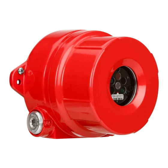
- Page 1 Installation and Operating Manual – FSX™ Fire and Flame Detectors Model FS24X™ FS24X QuadBand Triple IR™ Multi-Spectrum Infrared Electro-Optical Multi-Spectral Digital WideBand IR Sensor Radiant Energy Fire and Flame Detector...
- Page 2 This manual is subject to change without notice. © 2015-2018 by Honeywell International Inc. While this information is presented in good faith and believed to be accurate, Honeywell disclaims the implied warranties of merchantability and fitness for a particular purpose and makes no express warranties except as may be stated in its written agreement with and for its customers.
-
Page 3: Table Of Contents
4.6.2 False Alarm Immunity .......................... 24 4.7 Drawings ................................25 4.7.1 Outline and Dimensions ........................25 4.7.2 Wiring and Terminal Connections ......................26 4.7.3 BRE Detector Labels ..........................28 4.7.4 EN54 Detector Label ..........................29 INDEX ..................................30 CONTACT HONEYWELL ANALYTICS ........................31 Honeywell... -
Page 4: Section 1: Introduction
• Selecting a unique digital address (128 choices). • Factory Use 3. The ten (10) position Rotary switch Figure 1-3 allows selection of the analog and FS24X and FS24X-9 Detector Puck, ( rear view digital communication protocol. Honeywell... -
Page 5: Mechanical Specifications
Heater circuit turns ON only when temperature drops below zero (0) degrees Farenheit (-17° C) The supply connection wiring shall be rated at least 10°C above the rated service temperature (120°C for T4 applications and 85°C for T5 applications) Honeywell... -
Page 6: Flame Performance Certification
Flame Performance Certification (See Sections 4.7.3 and 4.7.4 on page 28 and 29) Agency Standard Certificate Notes LPCB EN 54-10:2002 +A1:2005 1175a/02 Sensitivity settings: Very High, High EN 54-10 Class 1 EN 54-10:2002 +A1:2005 0832-CPR-F0516 FM/cFM FM3260 Sensitivity: Very High Honeywell... -
Page 7: Features & Benefits
• FSC Windows® based PC Interface User can perform remote FSX Detector diagnostics, real-time status, Real-Time Graphing (RTG), SnapShot data recording, and downloading FirePic’s with Honeywell Analytics’ exclusive FSIM-2 USB ® Interface Unit and easy to use Windows based PC Software. -
Page 8: Section 2: Installation
Detector may cause the fire to be undetected. 5. The Model SM4 is a 316 Stainless Steel Swivel Mount designed for the Honeywell Analytics Detector housing. The adapter plate, with the two (2) screw holes (facing away), is attached to the base of the Detector (see Figure 2-1). - Page 9 3. There are no serviceable parts inside the Detector puck. If the puck is opened up or tampered with, all warranties are voided. CAUTION: Follow static protection procedures while handling the connectors and the wiring of the Module puck to the Detector. Use a wrist strap connected to earth ground. Honeywell...
-
Page 10: Opening The Detector
It is necessary to remove the Detector Module puck from the enclosure to access the field connections. CAUTION: Disconnect power before unscrewing the Housing Lid. 1. Loosen the set screw on the enclosure lid (see Figure 2-6). Figure 2-6 2. Turn counterclockwise (CCW) to unscrew the enclosure lid (see Figure 2-7). Figure 2-7 Honeywell... - Page 11 Installation and Operating Manual Opening the Detector (continued) 3. Loosen the three captive screws on the Detector Module puck (see Figure 2-8). Figure 2-8 4. Slide the Detector Module puck out of the enclosure base (see Figure 2-9). Figure 2-9 Honeywell...
-
Page 12: Detector Connections
Alarm COM 4-20mA Sink Figure 2-10 Fault NO Detector Puck, ( rear view Fault COM +24 VDC DC Return Contacts shown with no power applied Note: Do not attempt to open the Detector Module puck as this voids all warranties. Honeywell... - Page 13 Installation and Operating Manual Figure 2-11. Recommended Wiring Configurations Honeywell...
- Page 14 2. Avoid wire splices whenever possible. If wire splices are required, solder and properly insulate them. Good wiring practices simplify installation, improve reliability, and facilitate maintenance. 3. For applications requiring analog/digital communications, please refer to Section 3.2 of this Instruction Manual. Honeywell...
-
Page 15: Installation Practices
6. To ensure optimum performance, shield the detector face from intense bright light sources when first energized. The Detector is now ready for Power-Up. on Power-Up, the Fault Relay will change status if the Factory Default Setting is used (Section 3.2). Honeywell... -
Page 16: Start-Up And Commissioning
The TL-1055 and the TL-2055 are the only Test Lamps that will activate the FSX Detectors.. Additionally, do not use these Test Lamps to activate other Honeywell Analytics Detectors (nor any other conventional fire and flame detectors). Do not use other Honeywell Analytics Test Lamps or non-Honeywell Analytics Test Lamps to test the FSX Detectors. - Page 17 Remember to disable the outputs, as a full functional test includes activating the ALARM outputs. A Honeywell Analytics Test Lamp must be used for this test (Section 4.4). Point the Test Lamp directly at the front of the Detector (on axis as much as possible, within a distance of about 1 to 25 feet). Activate the Test Lamp by pressing and holding its pushbutton.
-
Page 18: Section 3: Operation
WideBand IR regions from approximately 1.1 to 3.0 microns and 3.0 to 5.0 microns. This allows the FS24X Detectors to sense over 85% of the total radiant “Blackbody Energy” emitted by a fire. Honeywell Analytics’ Detectors sense and measure the radiant energy generated by a fire at the speed of light. - Page 19 Figure 3-3 to configure SW3. Factory Use Only Factory Use Only Figure 3-3 SW3 10-Position Factory Use Only Rotary Switch Factory Use Only Note: The Medium and Low Sensitivity ranges are not approved as compliant with the requirements of EN 54-10:2002. Honeywell...
-
Page 20: Led Status Indicators
• 4-20 mA (source 20 mA) Output • RS-485 FireBus Alarm Notification • RS-485 Modbus Alarm Notification Figure 3-5 Red LED Location 1 This output is a Verified Alarm Output 2 Only one active Alarm output from this group Honeywell... -
Page 21: Fault Conditions
Additionally, semi-annual or quarterly testing should be performed, using the correct Honeywell Analytics Test Lamp, to ensure the integrity of the entire fire protection system. In order to ensure the Detector is operating properly at all times, it may be necessary to establish a periodic cleaning schedule. -
Page 22: Section 4: Appendix
Honeywell Analytics warrants its Products against defects in material and workmanship under normal use and service for a period of three years from the date of shipment as described herein. Honeywell Analytics, at its option, will repair or replace, at no charge, such products found to be defective during the warranty period provided that they are returned in accordance with the terms of this warranty. -
Page 23: Product Variations
2 = Relays / HART Communication Application 1 = General Applications Manufacturer’s Code 2 = Standard Honeywell Analytics Detector - 110° Field of View (-1 has been replaced by -2) 9 = Standard Honeywell Analytics Detector - 90° Field of View EXAMPLES: FS24X-911-21-1 QuadBand Triple IR Detector, 90°... -
Page 24: Digital Communication Options
Some manufacturers claim that their detectors do not need remote testing with an external Test Lamp because it tests itself. Even though Honeywell Analytics Detectors also perform “through the lens” self-testing and tests themselves, Honeywell Analytics, in compliance with NFPA 72 codes, has developed portable test lamps for periodical “end-to-end”... -
Page 25: Field Of View Restrictor
< 8 seconds Pine Needles 12 in X 12 in (0.3m X 0.3m) 50 feet (15 meters) < 8 seconds Wood 12 in X 12 in (0.3m X 0.3m) 90 feet (27 meters) 50 < 6 seconds feet (15 meters) Honeywell... -
Page 26: False Alarm Immunity
Source at 3 feet / 91.44 centimeters Pelican Flashlight 1 foot / 30.48 centimeters Fire at 200 feet / 60.96 meters Source at 3 feet / 91.44 centimeters Incandescent Lamp 1 foot / 30.48 centimeters Fire at 200 feet / 60.96 meters Honeywell... -
Page 27: Drawings
Installation and Operating Manual Drawings 4.7.1 Outline and Dimensions Figure 4-3 Outline & Dimesional Drawing for FS24X Figure 4-4 Outline & Dimesional Drawing for SM4 Honeywell... -
Page 28: Wiring And Terminal Connections
1. Cable shield must be grounded at one end only, at the Control Panel. Coil and tape cable shield at the Detector end. 2. Set SW3 (rotary switch) to position one (1) for Source current wiring. 3. Set SW3 (rotary switch) to position zero (0) for Sink current wiring. Honeywell... - Page 29 3. Fault relay contacts shown with no power applied. During normal operation and with no Fault, this relay will De-Energize and the N.O. (normally open) contacts will close. 4. EOL (End-Of-Line) device shall be installed as required and supplied by the Fire Alarm Panel. Honeywell...
- Page 30 FS24X-2 FS24X-2 FS24X-2 FS24X-2 FS24X-2 FS24X-2 FS24X-2 -60ºC to -60ºC to -60ºC to Label, 0.020” 316 QuadBand 1175a/02 +110ºC +75ºC +60ºC FS24X-9, ss, Stainless Triple IRTM Matte Black FS24X-9 0832-CPR- with Steel F0516 6095- FM/Canada/U S ATEX, IECEX approval Honeywell...
-
Page 31: Index
FireBus II, 13, 16, 17, 19, 20, 21, 22 Start-Up and Commissioning, 14 Hazardous Locations, 4, 5, 8, 14 Temperature, 19 Test Lamp, 14, 19, 22 Trouble, 19 Installation Practices, 13 Warranty, 20 weatherproof, 13 LEDs green, 7, 18 red, 7, 18 yellow, 7, 16, 18, 19 Honeywell... -
Page 32: Contact Honeywell Analytics
Honeywell Analytics Asia Pacific Co., Ltd. #701 Kolon Science Valley (1) 43 Digital-Ro 34-Gil, Guro-Gu Seoul, 152-729 Korea Email: [email protected] Internet These Honeywell websites may be of interest to Industry Solution customers. Honeywell Organization Corporate www.honeywell.com Honeywell Analytics www.honeywellanalytics.com Telephone Contact us by telephone at these numbers. - Page 33 Installation and Operating Manual 1998M0901 Revision D 2018 © 2015-2018 Honeywell International Inc.