Quick Links
❶
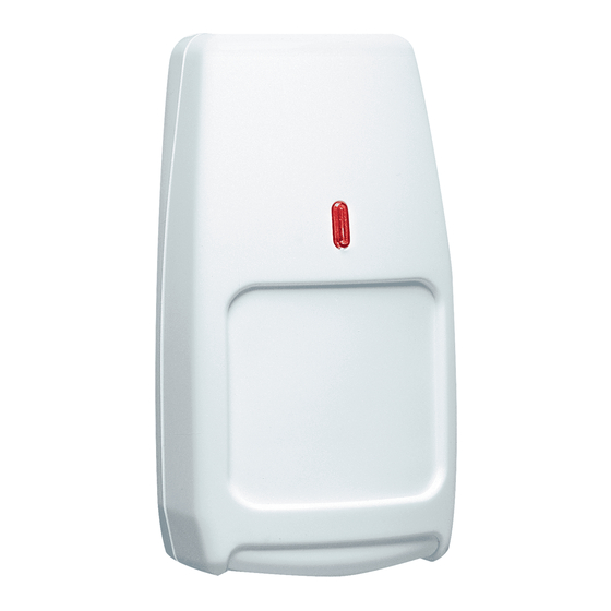
Select the mounting location.
Aim away from:
Mounting Location Guidelines
• 2.3 m - 2.7 m (7.5' - 9') mounting height.
• Avoid direct or reflected sunlight.
• Aim sensor away from windows or heating/cooling devices.
• Sensor must have a clear line-of-sight to protected area.
❺
Set the DIP switches.
Install the look-down mask (black
ring supplied) as shown, to reduce
End of Line
the look-down sensitivity if desired.
(EOL) Screws
Terminal
Block
LED
DIP
Switch
The PCB alignment
guide should
always point down,
as shown.
❷
Separate the sensor housings and remove the printed cir-
cuit board (PCB).
• Use a small screwdriver to remove the cover screw (if
installed), then push in the housing latch at the bottom of the
sensor, and gently pull apart the housings.
• Push outward on the PCB latch and lift the PCB out of the
housing.
SWITCH
OFF
ON
1 (PC)
Pulse Count 2
Pulse Count 1
2 (SENS)
Low Sensitivity
High Sensitivity
3 (LED)
LED Disabled
LED Enabled
4 (POL)
Active Low
Active High
Polarity
Test* Input
(L) = Test*; (H) = Normal
(H) = Test*; (L) = Normal
Arm Input
(L) = Arm; (H) = Disarm
(H) = Arm; (L) = Disarm
(Notes: Default switch settings are shown in grey.
See the Specifications section for more information on the
Test/Arm inputs. *Test = Remote LED Enable.)
❸
Mount the unit.
Wire
Knockouts
Corner
Mount
Strain Relief Options
Knockouts
Wall Mount
Knockouts
#6
pan-head
screws
Tamper Knockout
• Slide the wire through the wire knockouts in the
back housing, attach the wire with a wire tie,
and cut off the excess wire tie.
• Mount the back housing flat against a wall or in
a corner using #6 screws supplied. [Notes: If
using the wall tamper, refer to the Tamper
Switches section. If using a mounting bracket
see the Accessories section, and follow the
installation instructions supplied with the
bracket.]
• Replace the PCB.
• Seal any openings with RTV compound.
❻
Configure the sensitivity and walk-test the sensor.
Set the sensitivity appropriate for the application (see options below), replace the front cover, and apply power to the sensor. Begin walk-test
after the LED stops flashing (see the LED Operation section). Walk through the detection zones, observing the sensor's LED whenever motion is
detected. The red LED shows actual alarm relay operation.
The absolute range of all PIR units is subject to variation because of different types of clothing, backgrounds, and ambient temperature. For this reason,
ensure that the most likely intruder routes are well within the PIR's detection zones and that walk-testing is carried out along those routes.
Note: Pulse count 2 setting is not
recommended for long range devices.
❹
Wire the sensor. Connect wires to terminal as shown using wire size 0.8
- 1.5 mm (22-16 AWG). Observe the proper polarity.
Test/Arm
TAMPER
ALARM
POWER
Test/Arm
TAMPER
0 VDC - V
,
30 mA,
30 mA,
21 mA, 12 VDC,*
0 VDC - V
,
30 mA,
supply
supply
1.8 mA max
24 VDC
24 VDC
25 mA max
1.8 mA max
24 VDC
Normally Closed Loop, No EOL Resistor
Normally Open Loop, No EOL Resistor
Test/Arm
TAMPER
ALARM
POWER
Test/Arm
TAMPER
0 VDC - V
,
30 mA,
30 mA,
21 mA, 12 VDC,*
0 VDC - V
,
30 mA,
supply
supply
1.8 mA max
1.8 mA max
24 VDC
24 VDC
25 mA max
24 VDC
Normally Closed Loop, w/ EOL Resistors
Normally Open Loop, w/ EOL Resistors
Note: EOL = Single End-of-Line supervised resistor.
*For UL voltage, see Specifications Section.
Note: For High Security applications, disable the LED
(S3=OFF), and set the sensitivity to High (S1 and S2=ON).
ALARM
POWER
30 mA,
21 mA, 12 VDC,*
24 VDC
25 mA max
ALARM
POWER
30 mA,
21 mA, 12 VDC,*
24 VDC
25 mA max

Related Manuals for Honeywell IntelliSense IS25100TC


Summary of Contents for Honeywell IntelliSense IS25100TC
- Page 1 ❶ ❷ ❸ ❹ Select the mounting location. Separate the sensor housings and remove the printed cir- Mount the unit. Wire the sensor. Connect wires to terminal as shown using wire size 0.8 cuit board (PCB). - 1.5 mm (22-16 AWG). Observe the proper polarity. Wire Knockouts Corner...
-
Page 2: Specifications
Operation for 3 seconds for 3 seconds The user is cautioned that changes or modifications not expressly approved by Honeywell could void the user’s authority to operate this equipment. Trouble Fast Blink Fast Blink NOTE: This equipment as been tested and found to comply with the limits for a Class B digital device, pursuant to Part 15 of the FCC...