Quick Links
CC1101EMK 868/915 MHz Quick Start Guide
Opening the box and using the modules with SmartRF04EB
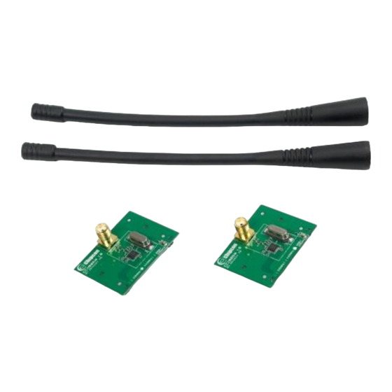
1. Kit Contents
2 x CC1101EM-868-915
2 x W5017 Pulse Antennas
The hardware in this kit is FCC/IC certified
and complies with ETSI/R&TTE over
temperature from 0 to +35°C.
The W5017 whip antenna from Pulse has a
gain of 2 dBi.
4a. Power: Battery
There are three different ways of applying
power to the EB:
The first method involves using a battery,
for instance a 9V battery (not included in
the kit) connected to the connector on the
bottom side of the board.
Warning! To minimize risk of personal
injury or property damage, never use
rechargeable batteries to power the board.
Do not leave the EVM powered when
unattended.
5. Set Power Switch
If a 3.3 V source is used as described in 4b
above, the switch should be set to the
leftmost position. For all other cases, the
switch should be set to the rightmost
position. This switch can be used to turn off
the EB by switching it to the opposite
position of that used to turn it on.
2. How to use the modules
The CC1101EM boards can be plugged
into several development boards from
Texas Instruments. Most notably, you can
use SmartRF04EB, which is included in the
CC1101DK,
or
the
SmartRF
(included in CC1120DK). These boards let
you run a packet error rate (PER) test,
control the device from SmartRF™ Studio
and it can be used as a general purpose
development platform.
The board can also be plugged into the
MSP430 Experimenter's Boards, both the
MSP-EXP430F4618
and
EXP430F5438.
For prototyping with other microcontrollers,
plug the EM into the "SoC Battery Board"
(www.ti.com/tool/soc-bb).
This guide will show how to use the
modules together with SmartRF04EB.
4b. Power: DC/External
The second method applies DC power
(max 10 V, min 4 V, 1500 mA) using the
DC input jack (right in picture, centre is +,
sleeve is ground), or by connecting a 4 - 10
V voltage source between the 4 - 10 V and
0 V terminals of the power connector (left
in picture). It is also possible to connect a
3.3 V voltage source between the 3.3 V
and 0 V terminals. The on-board voltage
regulators will be bypassed if the 3.3 V
input terminal is used.
6. Packet Error Rate Test
When power is applied to the board, the
PER test program will start. You should
see the text shown above on the LCD
display on both evaluation boards.
Press the button marked S1 (lower right
corner) to continue.
December 2012
3. Plug EM into SmartRF04EB
TrxEB
MSP-
Insert a CC1101EM (EM) with an antenna
into
the
SmartRF04EB
connectors will only fit in one position, so
that the EM cannot be inserted the wrong
way.
Caution! The kit contains ESD sensitive
components. Handle with care to prevent
permanent damage. To minimize risk of
injury, avoid touching components during
operation if symbolized as hot.
4c. Power: USB
The EB can also be powered from the USB
bus.
Note that there should only
be one active power source
at any one time
7. Set Frequency Band
Select the desired frequency band of
operation by using the joystick. The
frequency should match the evaluation
module and antenna you are using.
Note that the value shown in the display is
also the selected value. There is no need
to press a button to select or activate the
selection.
SWRU261A
(EB).
The

Related Manuals for Texas Instruments CC1101EMK


Summary of Contents for Texas Instruments CC1101EMK
- Page 1 SWRU261A December 2012 CC1101EMK 868/915 MHz Quick Start Guide Opening the box and using the modules with SmartRF04EB 1. Kit Contents 2. How to use the modules 3. Plug EM into SmartRF04EB The CC1101EM boards can be plugged into several development boards from Texas Instruments.
- Page 2 8. Set Network ID 9. Packet Length 10. Number of Packets Push the joystick down to display the Push the joystick down to display the Push the joystick down to display the screen shown above. This lets you set the screen shown above.
-
Page 3: Regulatory Compliance Information
Any exceptions to this are strictly prohibited and unauthorized by Texas Instruments unless user has obtained appropriate experimental/development licenses from local regulatory authorities, which is responsibility of user including its acceptable authorization. - Page 4 FCC Interference Statement for Class B EVM devices This equipment has been tested and found to comply with the limits for a Class B digital device, pursuant to part 15 of the FCC Rules. These limits are designed to provide reasonable protection against harmful interference in a residential installation. This equipment generates, uses and can radiate radio frequency energy and, if not installed and used in accordance with the instructions, may cause harmful interference to radio communications.
- Page 5 Also, please do not transfer this product, unless you give the same notice above to the transferee. Please note that if you could not follow the instructions above, you will be subject to penalties of Radio Law of Japan. Texas Instruments Japan Limited (address) 24-1, Nishi-Shinjuku 6 chome, Shinjuku-ku, Tokyo, Japan http://www.tij.co.jp...
- Page 6 FDA Class III or similar classification, then you must specifically notify TI of such intent and enter into a separate Assurance and Indemnity Agreement. Mailing Address: Texas Instruments, Post Office Box 655303, Dallas, Texas 75265 Copyright © 2012, Texas Instruments Incorporated...