Dell PowerEdge 1855 Installation And Troubleshooting Manual
Hide thumbs
Also See for PowerEdge 1855:
- Configuration manual (296 pages) ,
- User manual (33 pages) ,
- Quick start manual (12 pages)
Table of Contents
Quick Links
Dell™ PowerEdge™ 1855 Systems Installation and Troubleshooting Guide
Introduction
Indicators, Codes, and Messages
Finding Software Solutions
Running System Diagnostics
Troubleshooting Your System
Installing System Options
Getting Help
DIP Switch Settings and Connectors
I/O Ports and Connectors
Notes, Notices, and Cautions
NOTE:
A NOTE indicates important information that helps you make better use of your computer.
NOTICE:
A NOTICE indicates either potential damage to hardware or loss of data and tells you how to avoid the problem.
CAUTION:
A CAUTION indicates a potential for property damage, personal injury, or death.
Abbreviations and Acronyms
For a complete list of abbreviations and acronyms, see the "Glossary" in the User's Guide.
Information in this document is subject to change without notice.
© 2005 Dell Inc. All rights reserved.
Reproduction in any manner whatsoever without the written permission of Dell Inc. is strictly forbidden.
Trademarks used in this text: Dell, the DELL logo, Inspiron, Dell Precision, Dimension, OptiPlex, Latitude, PowerEdge, PowerConnect, PowerVault, PowerApp, and Dell OpenManage are
trademarks of Dell Inc.; Intel, Pentium, and Celeron are registered trademarks of Intel Corporation; Microsoft and Windows are registered trademarks of Microsoft Corporation.
Other trademarks and trade names may be used in this document to refer to either the entities claiming the marks and names or their products. Dell Inc. disclaims any
proprietary interest in trademarks and trade names other than its own.
Initial release: 20 August 2004
Last revised: 30 June 2005
Table of Contents
Troubleshooting

Related Manuals for Dell PowerEdge 1855


Summary of Contents for Dell PowerEdge 1855
- Page 1 Dell Inc.; Intel, Pentium, and Celeron are registered trademarks of Intel Corporation; Microsoft and Windows are registered trademarks of Microsoft Corporation. Other trademarks and trade names may be used in this document to refer to either the entities claiming the marks and names or their products. Dell Inc. disclaims any proprietary interest in trademarks and trade names other than its own.
-
Page 2: Dip Switch Settings And Connectors
Damage due to servicing that is not authorized by Dell is not covered by your warranty. Read and follow the safety instructions that came with the product. -
Page 3: Server Module Board Connectors
Table A-1. Server-Module DIP Switch Settings DIP Switch Setting Description PASSWD The password feature is enabled when switch 1 is set to "on." (Switch 1) (default) The password feature is disabled when switch 1 is set to "off." NVRAM_CLR The configuration settings in NVRAM are retained at system boot when switch 2 is set to "off." (Switch 2) (default) The configuration settings in NVRAM are cleared at next system boot when switch 2 is set to "on."... -
Page 4: Disabling A Forgotten Password
Damage due to servicing that is not authorized by Dell is not covered by your warranty. Read and follow the safety instructions that came with the product. - Page 5 4. Use a small plastic scribe to move the password switch 1 to the "off" position. Figure A-3 to locate the password switch 1 on the server module board. 5. If you removed a daughter card from the server module board, reinstall it. See "Installing a Daughter Card"...
-
Page 6: I/O Ports And Connectors
Back to Contents Page I/O Ports and Connectors Dell™ PowerEdge™ 1855 Systems Installation and Troubleshooting Guide I/O Connectors DRAC/MC Module Keyboard/Video/Mouse (KVM) Switch Module Custom Cable Front-Panel Keyboard/Video/Mouse (KVM) Module PowerConnect 5316M Ethernet Switch Module Gb Ethernet Pass-through Module Fibre Channel Pass-through Module and Fiber Channel Switch Module I/O Connectors... - Page 7 Signal ground Data set ready Request to send Clear to send Ring indicator Shell N/A Chassis ground 10/100 Management Port The DRAC/MC module's 10/100 management port allows you to manage the server modules. Figure B-2 illustrates the pin numbers for the management port Table B-3 defines the pin assignments for the port.
-
Page 8: Video Connector
Front-Panel Keyboard/Video/Mouse (KVM) Module USB Connector The front-panel custom cable provides a USB connector that supports USB-compliant devices such as diskette drives and CD drives (supplied by Dell). Figure B- illustrates the pin numbers for the USB connector and Table B-6 defines the pin assignments for the connector. - Page 9 PowerConnect 5316M Ethernet Port The system's PowerConnect 5316M Ethernet switch module's Ethernet ports provide fast uplink communications between servers and workstations. Figure B-6 illustrates the pin numbers for the ports and Table B-7 defines the pin assignments for the ports. Figure B-6. PowerConnect 5316M Ethernet Port Table B-7. PowerConnect 5316M Ethernet Port Pin Assignments ...
- Page 10 NOTICE: To avoid line interference, voice and data lines must be in separate sheaths. Use Category 5 or greater wiring and connectors. Do not exceed a cable run length (from a workstation to a hub) of 100 m (328 ft). NOTE: The cable used for the analog rack interface port is limited to 15.24 m (50 ft).
-
Page 11: Other Documents You May Need
Dell continues to offer new types of connectivity modules for your system and provides documentation on how to set up and use them. The documentation for a particular module is included with the module product or is available at support.dell.com. -
Page 12: Obtaining Technical Assistance
Obtaining Technical Assistance If at any time you do not understand a procedure described in this guide or if your system does not perform as expected, a number of tools are provided to help you. For more information on these help tools, see "Getting Help."... -
Page 13: System Overview
(see Figure 2-1). To function as a system, a server module is inserted into a chassis that supports power supplies, fan modules, a management module (Dell Remote Access Controller/Modular Chassis [DRAC/MC]), a KVM switch module, and at least one I/O module for network connectivity. -
Page 14: System Status Features
System Status Features The chassis has front-panel control features including power and identification buttons and indicators (see Figure 2-2). Press the power button to turn on the system; press and hold the power button to turn off the system. Pressing the identification button activates the identification indicator on both the front and back (on the KVM module) of the system. - Page 15 Table 2-2 provides information about the status indicators. Table 2-2. Server Module Features and Indicators Indicator Icon Activity Indicator Code Indicator Server module power indicator Power is not available to the server module, the server module is not turned on, or the server module is installed incorrectly.
-
Page 16: Using Usb Diskette Or Usb Cd Drives
Each server module has a USB port on the front of the server module which allows you to connect a custom cable for a diskette drive or USB CD drive. The USB drives are used to configure the server module. NOTICE: The system only supports USB 1.1 drives designated by Dell for use with your system. The drive must be horizontal and level to operate properly. NOTE: If the drive must be designated as the boot drive, enter the System Setup Program and set the drive as first in the boot sequence (see "Using... -
Page 17: Power Supply Indicator
The back of the chassis supports four I/O module bays, the DRAC/MC, fan modules, and power supply modules. Figure 2-5 shows a sample configuration and the numbering for the bays. Table 2-4 provides information about the back-panel features. Figure 2-5. Back-Panel Features Table 2-4. -
Page 18: Fan Module Indicators
Indicator Icon Activity Indicator Code Indicator DC power Green The power supply is operational. indicator Fault indicator Amber The power supply is in a fault condition. The fault condition can result from either a failed power supply or a failed fan within the power supply. -
Page 19: Avocent Digital Access Kvm Switch Module
NOTE: The ACI port can only be used to connect to ARI ports on Dell console switches. To connect to other types or brands of switches, including Avocent switches, you must connect to the switch's PS2 and video ports using the proprietary dongle provided with that switch. -
Page 20: Kvm Switch Module
NOTE: You must connect the switch's Ethernet port into the same network as the DRAC/MC port. You can then use the switch's Virtual Media and virtual KVM features: Virtual Media – Using this feature, you can remotely map local drives on a management workstation to the server module, or boot a server ¡... -
Page 21: Drac/Mc Module
The DRAC/MC is a backup for the master DRAC/MC. NOTE: For information on availability of dual (redundant) configurations for the DRAC/MC, see www.dell.com. Green The DRAC/MC is active for system management. Green The DRAC/MC is in special or manufacturing mode. -
Page 22: Redundancy Support
Otherwise, the module in bay 2 or bay 4 will be powered off if you perform a firmware upgrade procedure on the DRAC/MC, cause a DRAC/MC failover, or reset the DRAC/MC. See the current Dell Remote Access Controller/Modular Chassis User's Guide at support.dell.com for more information about configuring your DRAC/MC system. ... -
Page 23: Powerconnect 5316M Ethernet Switch Module
PowerConnect 5316M Ethernet Switch Module The PowerConnect 5316M Ethernet switch module is a 16-port switch with 6 uplinks and 10 downlinks (see Figure 2-12). The uplinks connect to the external Ethernet network and operate at 10/100/1000 Mb. The downlinks connect to the embedded Ethernet controller on the server module and operate at 1000 Mb only. -
Page 24: Fibre Channel Switch Module
Table 2-12. Fibre Channel Pass-Through Module Indicators Indicator Type Activity Indicator Code Indicator Fibre Channel indicator (green/amber) Power is off to the system. Green/amber System has power. Green/off Fibre Channel connection is online. Off/amber The port is connected to a valid link partner on the network. ... -
Page 25: Server Module Messages
Damage due to servicing that is not authorized by Dell is not covered by your warranty. Read and follow the safety instructions that came with the product. - Page 26 Faulty or improperly installed Ensure that all memory modules are properly installed. See "Troubleshooting Decreasing available memory memory modules. Server Module Memory" in "Troubleshooting Your System." Incorrect configuration Run the System Setup program to correct the settings. See "Using the System Diskette drive 0 seek failure settings in System Setup Setup Program"...
- Page 27 "Microprocessors" in "Installing System Options." Processor is not supported Check for a BIOS update using the Dell Support website at support.dell.com. by the server module. If the problem persists, install a supported processor. See "Microprocessors" in "Installing System Options."...
- Page 28 Damage due to servicing that is not authorized by Dell is not covered by your warranty. Read and follow the safety instructions that came with the product.
-
Page 29: Warning Messages
Warning Messages A warning message alerts you to a possible problem and prompts you to respond before the system continues a task. For example, before you format a diskette, a message will warn you that you may lose all data on the diskette. Warning messages usually interrupt the task and require you to respond by typing y (yes) or n (no). -
Page 30: Finding Software Solutions
Back to Contents Page Finding Software Solutions Dell™ PowerEdge™ 1855 Systems Installation and Troubleshooting Guide Before You Begin Troubleshooting Errors and Conflicts Software problems can be caused by: Improper installation or configuration of an application Application conflicts Input errors Interrupt assignment conflicts Ensure that you are installing the software application according to the software manufacturer's recommended procedures. If a problem occurs after you install the software, you might need to troubleshoot your software application and your system. - Page 31 IRQ Line Assignment IRQ0 System timer IRQ1 Keyboard controller IRQ2 Interrupt controller 1 to enable IRQ8 through IRQ15 IRQ3 Available IRQ4 Reserved for Console Redirection IRQ5 Remote access controller IRQ6 Available IRQ7 Available IRQ8 Real-time clock IRQ9 ACPI functions (used for power management) IRQ10 Available IRQ11...
-
Page 32: Using Server Administrator Diagnostics
Back to Contents Page Running System Diagnostics Dell™ PowerEdge™ 1855 Systems Installation and Troubleshooting Guide Using Server Administrator Diagnostics System Diagnostics Features When to Use the System Diagnostics Running the System Diagnostics System Diagnostics Testing Options Using the Advanced Testing Options Error Messages If you experience a problem with your server module, run the diagnostics before calling for technical assistance. The purpose of the diagnostics is to test your server module's hardware without requiring additional equipment or risking data loss. -
Page 33: From A Usb Flash Drive
See the documentation that came with your USB flash drive for instructions. 2. Configure the USB flash drive to be a bootable device. See the documentation that came with your USB flash drive for instructions. Dell also provides a USB memory key boot utility for download at support.dell.com. ... -
Page 34: Error Messages
Two lines at the top of the screen identify the diagnostics utility, the version number, and the system's service tag number. The left side of the screen under Device Groups lists the diagnostic device groups in the order that they are tested if you select All under the Run Tests submenu. -
Page 35: Troubleshooting Your System
Damage due to servicing that is not authorized by Dell is not covered by your warranty. Read and follow the safety instructions that came with the product. -
Page 36: Troubleshooting The Keyboard
Monitor or monitor cable Keyboard/video/mouse (KVM) custom cable KVM module Server module Action 1. Ensure that the server module(s) is turned on. 2. Check the monitor connection to the custom cable. Try swapping monitor cables if another monitor cable is available. ... -
Page 37: Troubleshooting The Mouse
green. If not, press the KVM selection button. See Figure 2-3. 6. If two or more server modules are installed in the chassis, press the KVM selection button on a different server module. NOTE: After pressing the KVM selection button, allow approximately two seconds for the KVM functions to change to a different server module. If the keyboard is connected to the back-panel KVM module and works with another server module, the first server module may need to be reseated. -
Page 38: Responding To A Systems Management Alert Message
Damage due to servicing that is not authorized by Dell is not covered by your warranty. Read and follow the safety instructions that came with the product. -
Page 39: Troubleshooting A Damaged System
14. Reconnect the power supply modules to their electrical outlets. If the system does not start up properly, see "Getting Help." 15. Run the Server Administrator diagnostics to confirm that the system is working properly (see "Running System Diagnostics"). -
Page 40: Troubleshooting Fan Modules
The power supply's fault indicator is amber if AC power is available. See Figure 2-6. If no indicators are lit, ensure that AC power is available from the electrical outlet and that the power cable is properly connected to the power supply module. -
Page 41: Troubleshooting Server Module Components
7. Connect a known-working serial device to the DRAC/MC module. If the serial device and DRAC/MC module still do not communicate with each other, see "Getting Help." 8. Reseat the network cable to the network connector on the DRAC/MC module and to the network device. ... -
Page 42: Troubleshooting Server Module Memory
Damage due to servicing that is not authorized by Dell is not covered by your warranty. Read and follow the safety instructions that came with the product. -
Page 43: Troubleshooting Microprocessors
Damage due to servicing that is not authorized by Dell is not covered by your warranty. Read and follow the safety instructions that came with the product. -
Page 44: Troubleshooting The Server Module Board
Damage due to servicing that is not authorized by Dell is not covered by your warranty. Read and follow the safety instructions that came with the product. - Page 45 4. Enter the System Setup program. If the date and time are not correct in the System Setup program, replace the battery. See "Server Module Battery" in "Installing System Options." If the problem is not resolved by replacing the battery, see "Getting Help."...
-
Page 46: Installing System Options
Back to Contents Page Installing System Options Dell™ PowerEdge™ 1855 Systems Installation and Troubleshooting Guide Power Supply Modules Fan Modules DRAC/MC Module KVM Module Chassis I/O Module Server Modules Removing and Installing Server Module Components The procedures in this section describe how to remove and install system components and server module components, including: Power supply modules... -
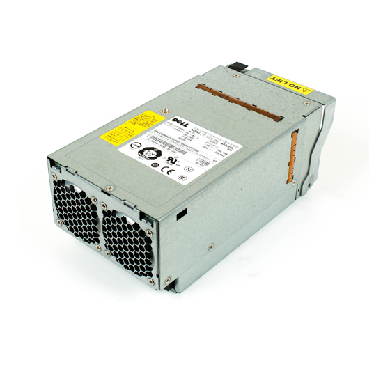
Page 47: Installing A Power Supply Module
4. Slide the power supply module out of the chassis. Figure 6-1. Removing and Installing a Power Supply Module Installing a Power Supply Module NOTICE: Depending on the type of power supply that you are installing, the back panel of the 2100-W power supply fits flush against the back of the chassis when it is proper seated, as shown in Figure 6-1. -
Page 48: Installing A Fan
3. Remove the failed fan: a. Pull up the fan-release tab. See Figure 6-3. b. Lift up the fan lever. c. Pull out the fan from the fan module. Figure 6-3. Removing and Installing a System Fan Installing a Fan ... -
Page 49: Installing A Drac/Mc Module
Otherwise, the module in bay 2 or bay 4 will be powered off if you perform a firmware upgrade procedure on the DRAC/MC, cause a DRAC/MC failover, or reset the DRAC/MC. See the current Dell Remote Access Controller/Modular Chassis User's Guide at support.dell.com for more information about configuring your DRAC/MC system. ... -
Page 50: Removing A Kvm Module
See the latest Dell Remote Access Controller/Modular Chassis User's Guide at support.dell.com for more information about firmware updates and installing redundant DRAC/MC modules. This guide also provides complete instructions on how to set up and operate that version of the module. - Page 51 Tiering a Avocent Analog KVM Switch or Avocent Digital Access KVM Switch From a Analog KVM Switch Both Avocent KVM switches can be tiered from analog KVM switches such as the Dell180ES and 2160ES, as well as other products that support the On-Screen Configuration and Activity Reporting (OSCAR) interface.
-
Page 52: Tiering An Avocent Analog Kvm Switch From A Dell Console Switch
Tiering an Avocent Analog KVM Switch From a Dell Console Switch To tier an Avocent Analog KVM switch from a Dell 2161DS, 180AS, or 2160AS console switch, connect the ACI port on the rear of the Avocent Analog KVM switch to one of the 16 ARI ports on the back of the Dell console switch (see Figure 6-8). -
Page 53: Tiering An Avocent Digital Access Kvm Switch From A Dell Console Switch
Tiering an Avocent Digital Access KVM Switch From a Dell Console Switch To tier a Avocent Digital Access KVM switch module from a Dell 2161DS, 180AS, or 2160AS console switch: 1. Connect one end of a CAT5 cable to an ARI port on the console switch (seeFigure 6-9.) ... -
Page 54: Chassis I/O Module
the drop-down list. If the type you are looking for is not available, you can add it by clicking Add. 6. Click Next. The completion dialog box appears. 7. Click Finish to exit. 8. Start up the analog switch and the system. Chassis I/O Module A variety of I/O modules, such as Fibre Channel pass-through, Fiber Channel switch, Ethernet pass-through, Infiniband pass-through, and PowerConnect 5316M Ethernet switch modules are available for your system. -
Page 55: Removing A Server Module
2. Install the I/O module. NOTE: Bays IO/1 and IO/2 accept only PowerConnect 5316M Ethernet switch modules or Gb Ethernet pass-through modules. If only one module is used, it must be installed in bay IO/1. Bay IO/2 is for a second PowerConnect 5316M Ethernet switch module or Gb Ethernet pass-through module for redundancy. -
Page 56: Opening The Server Module
Damage due to servicing that is not authorized by Dell is not covered by your warranty. Read and follow the safety instructions that came with the product. -
Page 57: Closing The Server Module
Damage due to servicing that is not authorized by Dell is not covered by your warranty. Read and follow the safety instructions that came with the product. -
Page 58: General Memory Module Installation Guidelines
If you remove your original memory modules from the system during a memory upgrade, keep them separate from any new memory modules that you may have, even if you purchased the new memory modules from Dell. Use only registered ECC DDR II memory modules. -
Page 59: Installing Memory Modules
Damage due to servicing that is not authorized by Dell is not covered by your warranty. Read and follow the safety instructions that came with the product. -
Page 60: Removing Memory Modules
Damage due to servicing that is not authorized by Dell is not covered by your warranty. Read and follow the safety instructions that came with the product. -
Page 61: Removing The Processor
Damage due to servicing that is not authorized by Dell is not covered by your warranty. Read and follow the safety instructions that came with the product. -
Page 62: Installing The Processor
Damage due to servicing that is not authorized by Dell is not covered by your warranty. Read and follow the safety instructions that came with the product. -
Page 63: Server Module Battery
Damage due to servicing that is not authorized by Dell is not covered by your warranty. Read and follow the safety instructions that came with the product. -
Page 64: Hard Drives
3. Remove the system battery by lifting it straight up from its connector. See Figure 6-20. Figure A-3 to locate the system battery on the server module board. 4. Install the new system battery with the side labeled "+" facing toward the inside of the server module. See Figure 6-20. Figure 6-20. -
Page 65: Removing A Scsi Hard Drive
Installing a Hard Drive NOTICE: When a replacement hot-pluggable hard drive is installed and the server module is powered on, the hard drive automatically begins to rebuild. Make absolutely sure that the replacement hard drive is blank or contains data that you wish to have over-written. Any data on the replacement hard drive is immediately lost after the hard drive is installed. - Page 66 The drive or device from which the system boots is determined by the boot order specified in the System Setup program (see "Using the System Setup Program" in your User's Guide). Back to Contents Page ...
-
Page 67: Getting Help
Dell's Express Service Code system may not be available in all countries. When prompted by Dell's automated telephone system, enter your Express Service Code to route the call directly to the proper support personnel. If you do not have an Express Service Code, open the Dell Accessories folder, double-click the Express Service Code icon, and follow the directions. -
Page 68: Dell Enterprise Training And Certification
Product Information If you need information about additional products available from Dell, or if you would like to place an order, visit the Dell website at www.dell.com. For the telephone number to call to speak to a sales specialist, see the contact information for your region. -
Page 69: Before You Call
In certain countries, technical support specific to Dell XPS portable computers is available at a separate telephone number listed for participating countries. If you do not see a telephone number listed that is specific for XPS portable computers, you may contact Dell through the technical support number listed and your call will be routed appropriately. - Page 70 0820 240 530 14 Preferred Accounts/Corporate Customer Care 0820 240 530 16 Country Code: 43 Technical Support for XPS portable computers only 0820 240 530 81 City Code: 1 Home/Small Business Technical Support for all other Dell computers 0820 240 530 14 Preferred Accounts/Corporate Technical Support 0660 8779 Switchboard 0820 240 530 00 Bahamas General Support toll-free: 1-866-278-6818...
- Page 71 Switchboard 22537 2711 Website: support.euro.dell.com E-mail: support.euro.dell.com/dk/da/emaildell/ Technical Support for XPS portable computers only 7010 0074 Technical Support for all other Dell computers 7023 0182 Denmark (Copenhagen) Customer Care (Relational) 7023 0184 International Access Code: 00 Home/Small Business Customer Care 3287 5505...
- Page 72 E-mail: support.euro.dell.com/fr/fr/emaildell/ Home and Small Business Technical Support for XPS portable computers only 0825 387 129 Technical Support for all other Dell computers 0825 387 270 Customer Care 0825 823 833 France (Paris) (Montpellier) Switchboard 0825 004 700 Switchboard (calls from outside of France) 04 99 75 40 00...
- Page 73 0120-198-226 Technical Support outside of Japan (Dimension and Inspiron) 81-44-520-1435 Technical Support (Dell Precision, OptiPlex, and Latitude) toll-free:0120-198-433 Technical Support outside of Japan (Dell Precision, OptiPlex, and Latitude) 81-44-556-3894 Japan (Kawasaki) Technical Support (PDAs, projectors, printers, routers) toll-free: 0120-981-690...
- Page 74 Transaction Sales (Xiamen, China) 29 693 115 Website: support.ap.dell.com Malaysia (Penang) Technical Support (Dell Precision, OptiPlex, and Latitude) toll-free: 1 800 880 193 Technical Support (Dimension, Inspiron, and Electronics and Accessories) toll-free: 1 800 881 306 International Access Code: 00 Technical Support (PowerApp, PowerEdge, PowerConnect, and PowerVault) toll-free: 1800 881 386...
- Page 75 Technical Support for XPS portable computers only 815 35 043 Norway (Lysaker) Technical Support for all other Dell products 671 16882 International Access Code: 00 Relational Customer Care 671 17575 Country Code: 47 Home/Small Business Customer Care 23162298 Switchboard 671 16800 Fax Switchboard 671 16865...
- Page 76 Switzerland (Geneva) Technical Support for XPS portable computers only 0848 33 88 57 International Access Code: 00 Technical Support (Home and Small Business) for all other Dell products 0844 811 411 Country Code: 41 Technical Support (Corporate) 0844 822 844 Customer Care (Home and Small Business) 0848 802 202...
- Page 77 Automated Order-Status Service toll-free: 1-800-433-9014 AutoTech (portable and desktop computers) toll-free: 1-800-247-9362 Technical Support (Dell TV, Printers, and Projectors) for Relationship toll-free 1-877-459-7298 customers Consumer (Home and Home Office) Technical Support for all other Dell toll-free: 1-800-624-9896 products Customer Service toll-free: 1-800-624-9897 toll-free: 1-877-Dellnet DellNet™ Service and Support (1-877-335-5638) Employee Purchase Program (EPP) Customers toll-free: 1-800-695-8133 Financial Services website: www.dellfinancialservices.com ...
- Page 78 Dell Inc.; Intel, Pentium, and Celeron are registered trademarks of Intel Corporation; Microsoft and Windows are registered trademarks of Microsoft Corporation. Other trademarks and trade names may be used in this document to refer to either the entities claiming the marks and names or their products. Dell Inc. disclaims any proprietary interest in trademarks and trade names other than its own.