Table of Contents
Quick Links
Service Manual
Design may vary by model number.
Safety Precautions/Introduction ................................................................................................. 3
Outdoor Unit Controls and Components ..................................................................................... 7
Indoor Unit Controls and Components ...................................................................................... 13
Sequence of Operation .............................................................................................................. 19
System Specifications ............................................................................................................... 28
Error Codes and Troubleshooting .............................................................................................. 29
Reference Information .............................................................................................................. 62
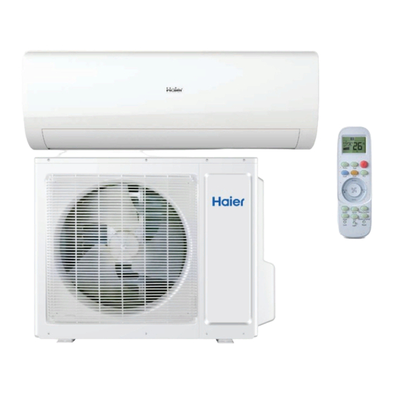
Ductless Split Heat Pump
Indoor
AW24TL2HFA
AW30TL2HFA
AW36TL2HFA
ASYW24TRDFA
ASYW30TRDFA
ASYW36TRDFA
• Please read this manual before installing this product.
• Keep this user manual for future reference.
Table of Contents
Outdoor
1U24TL2HFA
1U3036TL2HFA
ASH124TRDFA
ASH3036TRDFA
PAGE 1
Chapters
Table of Contents

Related Manuals for Haier GE Appliances AW24TL2HFA


Summary of Contents for Haier GE Appliances AW24TL2HFA
- Page 1 Ductless Split Heat Pump Indoor Outdoor AW24TL2HFA 1U24TL2HFA AW30TL2HFA 1U3036TL2HFA AW36TL2HFA ASH124TRDFA ASYW24TRDFA ASH3036TRDFA ASYW30TRDFA ASYW36TRDFA Service Manual • Please read this manual before installing this product. Design may vary by model number. • Keep this user manual for future reference. Table of Contents Safety Precautions/Introduction ....................
- Page 2 [This page intentionally left blank.]...
- Page 3 Introduction Table of Contents Safety Precautions ................................4 Warnings and Cautions ..................................4 Introduction ..................................5 Introduction to the System ................................5 Specifications for Proper Operation ...............................5 System Fundamentals ..................................5 INTRODUCTION PAGE 3...
- Page 4 Safety Precautions • Read these Safety Precautions carefully to ensure correct installation. • This manual classifies the precautions into WARNING and CAUTION. • Be sure to follow all the precautions bellow: they are all important for ensuring safety. WARNING: Failure to follow any of WARNING is likely to result in grave consequences such as death or serious injury. CAUTION: Failure to follow any of CAUTION may in some cases result in grave consequences.
- Page 5 Introduction The inverter compressor system in the outdoor unit will vary Introduction to the System the refrigerant flow and indoor air volume levels to match Single Zone Ductless Split System Heat Pumps feature a wall the comfort requirement inside the conditioned space. If an mounted indoor fan/evaporator unit that receives refrigerant abnormal condition is detected by the system’s sensors, the from an inverter driven variable speed outdoor condensing...
- Page 6 [This page intentionally left blank.] PAGE 6 INTRODUCTION...
-
Page 7: Table Of Contents
Outdoor Unit Controls and Components Table of Contents Outdoor Unit Introduction ..............................8 Outdoor Component Identification ............................ 8 PCB ....................................9 Terminal Block .................................. 10 Power Factor Reactor ............................... 10 Compressor ..................................10 Outdoor Fan Motor ................................10 Discharge Temperature Sensor ............................11 Defrost Temperature Sensor A ............................ -
Page 8: Outdoor Unit Introduction
Outdoor Unit Introduction The outdoor unit has two circuit boards, an Inverter Power Module (IPM) that drives the compressor and main control board (PCB) that manages system functions and inverter calculations. Sensors monitor key temperatures throughout the system to manage operational decisions. Outdoor Component Identification 4-Way Valve Accumulator... -
Page 9: Pcb
PCB (1) (Outdoor Control PCB) CN1 and CN2 - 230 VAC power from terminal block connections 1(N) and 2(L), CN6-connector for COM-N CN3 - Connector for ground CN4 -Communication connection between the indoor board and the outdoor board CNS and CN9 - 230 VAC power to the IPM connections CN8 (or CN1) and CN9 (or CN2) CN21- Connector for fan motor CN10 - Connector for four way valve coil... -
Page 10: Terminal Block
Terminal Block Compressor The outdoor unit is powered by 208/230 volt single phase electricity connected at the terminal block. Terminals 1 L (L1) and 2 N( L2) connect this voltage to the system. The compressor is a three phase DC inverter driven rotary type, capable of variable speed operation. -
Page 11: Discharge Temperature Sensor
Discharge Temperature Sensor Ambient Temperature Sensor The Discharge Temperature Sensor is a negative coefficient thermistor that senses the temperature of the compressor hot gas. The PCB monitors the temperature of the compressor hot gas and will make inverter speed changes in The Ambient Temperature Sensor is a negative coefficient response to input from this device. -
Page 12: 4-Way Valve
4-Way Valve Accumulator The 4-Way Valve redirects the flow of refrigerant in the piping The Accumulator is located in the suction line circuit at the circuit to allow the system to reverse the functions of the entrance to the compressor. The accumulator helps prevent indoor and outdoor coils. - Page 13 Indoor Unit Controls and Components Table of Contents Indoor Unit Introduction ..............................14 Indoor Component Identification ............................. 14 Indoor Control Board ................................ 15 Terminal Block .................................. 16 Display ..................................... 16 Ambient Temperature Sensor ............................16 Piping Temperature Sensor .............................. 16 Stepper Louver Motor ..............................
-
Page 14: Indoor Unit Introduction
Indoor Unit Introduction The indoor unit is mounted high on the wall to provide comfort and air movement within the conditioned space. Features of the system include: Variable speed blower operation that speeds up and slows down with changes in demand, moving louvers to direct air, indoor air temperature sensing, evaporator coil temperature sensing, a status display, evaporator coil with metering device located in outdoor unit, and an emergency ope ration button. -
Page 15: Indoor Control Board
Indoor Control Board CN9-Connector for fan motor CN35-Connector for WiFi module CN6 - Connector for pipe temperature sensor CN56-Connector for occupancy sensor and room temperature sensor CN5-1 - Connector for UP/DOWN STEP CN34-Connector for wired controller interface motor 1 CN5 - Connector for UP/DOWN STEP motor 2 CN38-Connector for diagnostic port CN14-Connector for forced operation CN21 - Connector for power N... -
Page 16: Terminal Block
Terminal Block Ambient Temperature Sensor The unit terminal block receives electrical power from the The Ambient (room) Temperature Sensor is a negative outdoor unit. There are 4 connections for electrical wires. coefficient thermistor that will decrease in resistance with Terminals 1 and 2 are connected to terminals 1 and 2 of the increases in room air temperature. -
Page 17: Stepper Louver Motor
Stepper Motor Louver Emergency Button If the remote control is non-functional, the Emergency Button can be used. 73F -78F degrees will be maintained, until commands are received via the remote control. The STEPPER MOTOR 1 and 2 moves the louver up or down, depending upon selections made at the remote control. -
Page 18: Dip Switch And Dip Switch Settings
DIP Switch DIP Switch Settings The PCB has a set of DIP switches that must be set when replacing the PCB. The replacement PCB is shipped with all switches set to the OFF position. Switch settings: J5 Selects remote code A or B. Normally set to connection state for code A operation. - Page 19 Sequence of Operation Table of Contents System Power .................................. 20 Cool Mode ..................................20 Overview ......................................20 Indoor Unit ..................................... 20 Indoor Temperature Sensors ............................... 20 Communication ..................................... 20 Outdoor Unit ....................................20 Outdoor Temperature Sensors ..............................21 Call to Terminate Cooling ................................21 Freeze Protection Function ................................
-
Page 20: System Power
System Power Indoor Unit The signals received by the infrared receiver are relayed to the The 240 Volt AC power for the system connects to terminals main board of the indoor unit to turn the system on and set it 1(N), 2(L), and ground of the outdoor unit terminal block. -
Page 21: Outdoor Temperature Sensors
The outdoor unit will shift the 4-way valve to the heat mode Outdoor Temperature Sensors position and determine the position of the EEV and speed Five temperature sensors located in the outdoor unit provide (frequency) of the compressor. There can be a delay of up to 3 temperature information to the outdoor unit main board for minutes before the outdoor unit fan and compressor start. -
Page 22: Defrost
Communication The indoor unit fan will continue to run at minimum speed until indoor coil temperature reaches a minimum temperature, The indoor and outdoor unit main boards communicate via a when it will turn off. digital signal on the wire connected to terminal 3 of each unit. A splice or break in this wire will cause a communication error. -
Page 23: Auto Mode
provides the main board with information for controlling the Auto Mode speed of the fan motor. With the system turned on, press the AUTO button on the remote control. The system will change to the auto mode of Indoor Temperature Sensors operation. -
Page 24: Defrost Operation
Defrost Operation Protection Functions Defrost cycle will initiate if any of three conditions are met: Compressor High Temperature Te = Defrost temperature sensor The compressor discharge pipe sensor (exhaust temp) senses Tao = Outdoor ambient temperature sensor the temperature of the refrigerant exiting the compres- Tes = Condensation point temperature sor. -
Page 25: Anti-Freeze Protection Of The Coil
Anti-Freeze Protection of the Indoor Coil Special Functions The temperature sensed by the coil sensor is used to deter- Auto Restart mine at what speed the compressor is to run to avoid the coil temperature being too cold. When this is enabled, the following functions will automatically resumes after a power loss: Tpg_indoor: indoor unit pipe sensor temperature •... -
Page 26: Smarthq
Part 1: Guide: Determine whether the e-star installation program is 1. Apply power to the unit. required: 2. Set to Cooling Mode or Heating Mode. • 1. If CC is displayed alternately on the dual-8 display 3. Set the temperature to 75°F. boards of the indoor unit during the initial power-on, it 4. - Page 27 procedure and the user can use it normally. • 2. If you have entered the self-check program, you need to power off the machine, power on again, wait for the internal machine CC display, then skip the self-check program operation. Part 4: Test mode for manual measurements •...
- Page 28 165/50 Maximum Height Ft / m 100/30 100/30 100/30 Ships with Remote Controller YR-HG (Haier or GE logo) YR-HG (Haier or GE logo) YR-HG (Haier or GE logo) Compatible with Remote Controller Cool Only (No logo) Cool Only (No logo)
- Page 29 Error Codes and Troubleshooting Table of Contents Check This First Outdoor Unit ............................30 Check This First Indoor Unit ............................. 31 Indoor/Outdoor Error Codes ............................33 F1/LED1: 2 Flash ................................... 34 F2/LED1: 24 Flash ..................................36 F3/LED1: 4 Flash ................................... 38 F4/LED1: 8 Flash ...................................
-
Page 30: Check This First Outdoor Unit
Error Codes and Troubleshooting Conditions Needed for Basic Operation Check This First Outdoor Unit 3-minutes of time delay from the call for heating or cooling Models: 1U24TL2HFA Line voltage available at: • 1 (N) and 3 (C): 0-80 1U3036TL2HFA 1. TERMINAL STRIP - 1(N) & 2 (L) VAC fluctuating ASH124TRDFA 2. -
Page 31: Check This First Indoor Unit
Error Codes and Troubleshooting Check This First See following page for wiring diagram, relevant color-coded test Indoor Unit positions, and sensor There is 230 VAC (+/- 10%) at terminal Models: resistance values. strip connections 1(N) and 2(L), and AW24TL2HFA no more than a 2% deviation between AW30TL2HFA each leg and ground? AW36TL2HFA... - Page 32 Indoor Board Diagram Error Codes and Troubleshooting Check This First - Indoor Unit Wiring Diagram Reference DC FAN MOTOR Diagnostic RJ45 CN38 port B:Black R:Red W:White BL:Blue ● HUMAN SENSOR CN56 Y:Yellow BR:Brown Y/G:Yellow/Green CN35 WIFI CN21 CN51 ROOM CARD CN34 WK-B WIRED CONTROLLER...
-
Page 33: Indoor/Outdoor Error Codes
Indoor Board Diagram Error Codes and Troubleshooting Check This First - Indoor Unit Wiring Diagram Reference DC FAN MOTOR Diagnostic RJ45 CN38 port B:Black R:Red W:White BL:Blue ● HUMAN SENSOR CN56 Y:Yellow BR:Brown Y/G:Yellow/Green CN35 WIFI CN21 CN51 ROOM CARD CN34 WK-B WIRED CONTROLLER... -
Page 34: F1/Led1: 2 Flash
Error Codes and Troubleshooting See following page Error Code Start (Indoor/Outdoor) for wiring diagram, F1/LED1: 2 Flash relevant color-coded test positions, and EEV IPM Power Module Fail Cycle power to the outdoor resistance values. (IPM power module protection) unit. Does LED1 flash 2 times before the compressor starts? Complete the “Check This First” Flow Chart before continuing. - Page 35 Error Codes and Troubleshooting Error Code: F1/LED1: 2 Flash Outdoor Board Diagram Wiring Diagram Reference OUTDOOR UNIT WIRING DIAGRAM 0011520512 COMPRESSOR Electrical Shock Hazard Riesgo de Descarga Eléctrica Risque de choc électrique Capacitor retains charge a er El capacitor re enecargaunavez Le condensateur conserve sa charge après la coupure de l’alimenta on électrique.
-
Page 36: F2/Led1: 24 Flash
Error Codes and Troubleshooting See following page Error Code (Indoor/Outdoor) for wiring diagram and Start F2/LED1: 24 Flash relevant color-coded test positions. Overcurrent of the Compressor The set temperature is 5°F max. Complete the “Check This First” Flow from the room temperature? Chart before continuing. Models: AW24TL2HFA AW30TL2HFA AW36TL2HFA Does the error code display... - Page 37 Error Codes and Troubleshooting Error Code: F2/LED1: 24 Flash Outdoor Board Diagram Wiring Diagram Reference OUTDOOR UNIT WIRING DIAGRAM 0011520512 COMPRESSOR Electrical Shock Hazard Riesgo de Descarga Eléctrica Risque de choc électrique Capacitor retains charge a er El capacitor re enecargaunavez Le condensateur conserve sa charge après la coupure de l’alimenta on électrique.
-
Page 38: F3/Led1: 4 Flash
Error Codes and Troubleshooting See following page Start Error Code (Indoor/Outdoor) for wiring diagram and F3/LED1: 4 Flash relevant color-coded Line voltage at AC-L & AC-N test positions. Communication Fault Between IPM and on the PCB (CN2 & CN1)? Outdoor PCB Complete the “Check This First” Flow Chart before continuing. - Page 39 Error Codes and Troubleshooting Error Code: F3/LED1: 4 Flash Outdoor Board Diagram Wiring Diagram Reference OUTDOOR UNIT WIRING DIAGRAM 0011520512 COMPRESSOR Electrical Shock Hazard Riesgo de Descarga Eléctrica Risque de choc électrique Capacitor retains charge a er El capacitor re enecargaunavez Le condensateur conserve sa charge après la coupure de l’alimenta on électrique.
-
Page 40: F4/Led1: 8 Flash
Error Codes and Troubleshooting See following page Error Code Start (Indoor/Outdoor) for wiring diagram, F4/LED1: 8 Flash relevant color-coded test positions, and EEV Overheat Protection For Discharge The discharge line temperature resistance values. Temperature is below 230°F/110°C? Complete the “Check This First” Flow Chart before continuing. Models: AW24TL2HFA Refrigerant static test (system AW30TL2HFA... - Page 41 Error Codes and Troubleshooting Error Code: F4/LED1: 8 Flash Outdoor Board Diagram Wiring Diagram Reference OUTDOOR UNIT WIRING DIAGRAM 0011520512 COMPRESSOR Electrical Shock Hazard Riesgo de Descarga Eléctrica Risque de choc électrique Capacitor retains charge a er El capacitor re enecargaunavez Le condensateur conserve sa charge après la coupure de l’alimenta on électrique.
-
Page 42: F6/Led1: 12 Flash
Error Codes and Troubleshooting See following page for Error Codes Start (Indoor/Outdoor) wiring diagram, relevant F6/LED1: 12 Flash color-coded test positions, and sensor Ambient Temperature Sensor Failure Is connector plugged in and resistance values. F7/LED1: 11 Flash seated securely? Suction Temperature Sensor Failure F21/LED1: 10 Flash Defrost Temperature Sensor Failure F25/LED1: 13 Flash... - Page 43 Error Codes and Troubleshooting Error Code: F6/LED1: 12 Flash, F7/LED1: 11 Flash, F21/LED1: 10 Flash, F25/LED1: 13 Flash, Outdoor Board Diagram E1/LED1: No Flash, E2/LED1: No Flash Wiring Diagram Reference OUTDOOR UNIT WIRING DIAGRAM 0011520512 COMPRESSOR VHA AW12ES2VHA AW18ES2VHA AW24E Indoor Board Diagram Electrical Shock Hazard Riesgo de Descarga Eléctrica...
- Page 44 Error Codes and Troubleshooting Error Code: F6/LED1: 12 Flash, F7/LED1: 11 Flash, F21/LED1: 10 Flash, F25/LED1: 13 Flash, Outdoor Board Diagram E1/LED1: No Flash, E2/LED1: No Flash Wiring Diagram Reference OUTDOOR UNIT WIRING DIAGRAM 0011520512 COMPRESSOR VHA AW12ES2VHA AW18ES2VHA AW24E Indoor Board Diagram Electrical Shock Hazard Riesgo de Descarga Eléctrica...
-
Page 45: F8/Led1: 9 Flash
Error Codes and Troubleshooting See following page Error Code (Indoor/Outdoor) for wiring diagram and F8/LED1: 9 Flash relevant color-coded Start test positions. Outdoor DC Fan Motor Fault Complete the “Check This First” Flow Check the incoming voltage. Chart before continuing. Is it 208/230VAC (+/- 10%) between L1/L2? Models: 104/115VAC (+/- 10%) from L1 to GROUND and L2 to GROUND? AW24TL2HFA... - Page 46 Error Codes and Troubleshooting Error Code: F8/LED1: 9 Flash Outdoor Board Diagram Wiring Diagram Reference OUTDOOR UNIT WIRING DIAGRAM 0011520512 COMPRESSOR Outdoor Board Diagram Electrical Shock Hazard Riesgo de Descarga Eléctrica Risque de choc électrique Capacitor retains charge a er El capacitor re enecargaunavez Le condensateur conserve sa charge après la coupure de l’alimenta on électrique.
-
Page 47: F11/Led1: 18 Flash
Error Codes and Troubleshooting See following page Error Code Start (Indoor/Outdoor) for wiring diagram and F11/LED1: 18 Flash relevant color-coded test positions. Loss of Compressor Synchronization When power is off for 5 min. and turned back on, Complete the “Check This First” Flow the compressor runs? Chart before continuing. - Page 48 Error Codes and Troubleshooting Error Code: F11/LED1: 18 Flash Outdoor Board Diagram Wiring Diagram Reference OUTDOOR UNIT WIRING DIAGRAM 0011520512 COMPRESSOR Electrical Shock Hazard Riesgo de Descarga Eléctrica Risque de choc électrique Capacitor retains charge a er El capacitor re enecargaunavez Le condensateur conserve sa charge après la coupure de l’alimenta on électrique.
-
Page 49: F12/Led1: 1 Flash
Error Codes and Troubleshooting Error Code Start (Indoor/Outdoor) F12/LED1: 1 Flash EEPROM Error After 10 minutes with the power off, the 1-flash reappears with Complete the “Check This First” Flow power turned back on? Chart before continuing. Models: AW24TL2HFA AW30TL2HFA AW36TL2HFA The 10-minute Replace ASYW24TRDFA reboot has ASYW30TRDFA corrected the ASYW36TRDFA... -
Page 50: E5/Led1: 22 Flash
Error Codes and Troubleshooting See following page for Error Code Start (Indoor/Outdoor) wiring diagram, relevant E5/LED1: 22 Flash color-coded test positions, sensor and Coil Frost Protection There is 5 VDC at CN6 on the Indoor EEV resistance values. PCB across the black senor wires? Complete the “Check This First” Flow Chart before continuing. - Page 51 Indoor Board Diagram Error Codes and Troubleshooting Error Code: E5/LED1: 22 Flash Wiring Diagram Reference DC FAN MOTOR Diagnostic RJ45 CN38 port B:Black R:Red W:White BL:Blue ● CN56 HUMAN SENSOR Y:Yellow BR:Brown Y/G:Yellow/Green CN35 WIFI CN21 CN51 ROOM CARD CN34 WK-B WIRED CONTROLLER OFF OFF OFF OFF...
- Page 52 Indoor Board Diagram Error Codes and Troubleshooting Error Code: E5/LED1: 22 Flash Wiring Diagram Reference DC FAN MOTOR Diagnostic RJ45 CN38 port B:Black R:Red W:White BL:Blue ● CN56 HUMAN SENSOR Y:Yellow BR:Brown Y/G:Yellow/Green CN35 WIFI CN21 CN51 ROOM CARD CN34 WK-B WIRED CONTROLLER OFF OFF OFF OFF...
-
Page 53: E7/Led1: 15 Flash
Error Codes and Troubleshooting See following page Error Code Start (Indoor/Outdoor) for wiring diagram and E7/LED1: 15 Flash relevant color-coded test positions. ID and OD Loss of Communication The control wire is 14/4 stranded Complete the “Check This First” Flow copper on the correct terminals, with Chart for both ID and OD units before no splices or loose connections? continuing. - Page 54 Error Codes and Troubleshooting Error Code: E7/LED1: 15 Flash Wiring Diagram Reference DC FAN MOTOR Diagnostic RJ45 CN38 port B:Black R:Red W:White BL:Blue ● CN56 HUMAN SENSOR Y:Yellow BR:Brown Y/G:Yellow/Green CN35 WIFI CN21 CN51 ROOM CARD CN34 WK-B WIRED CONTROLLER OFF OFF OFF OFF CN17 CENTRALIZED CONTROLLER...
- Page 55 Error Codes and Troubleshooting Error Code: E7/LED1: 15 Flash Wiring Diagram Reference DC FAN MOTOR Diagnostic RJ45 CN38 port B:Black R:Red W:White BL:Blue ● CN56 HUMAN SENSOR Y:Yellow BR:Brown Y/G:Yellow/Green CN35 WIFI CN21 CN51 ROOM CARD CN34 WK-B WIRED CONTROLLER OFF OFF OFF OFF CN17 CENTRALIZED CONTROLLER...
- Page 56 Error Codes and Troubleshooting Error Code: E7/LED1: 15 Flash Outdoor Board Diagram Wiring Diagram Reference OUTDOOR UNIT WIRING DIAGRAM 0011520512 COMPRESSOR Electrical Shock Hazard Riesgo de Descarga Eléctrica Risque de choc électrique Capacitor retains charge a er El capacitor re enecargaunavez Le condensateur conserve sa charge après la coupure de l’alimenta on électrique.
-
Page 57: E14
Error Codes and Troubleshooting See following page Error Code Start (Indoor) for wiring diagram and relevant color-coded test positions. Indoor Fan Motor Failure Check the incoming voltage. Is it 208/230VAC (+/- 10%) between L1/L2? 104/115VAC (+/- Complete the “Check This First” Flow 10%) from L1 to GROUND and L2 to GROUND? Chart before continuing. - Page 58 Error Codes and Troubleshooting Error Code: E14 Wiring Diagram Reference DC FAN MOTOR Diagnostic RJ45 CN38 port R:Red B:Black W:White BL:Blue ● HUMAN SENSOR CN56 Y:Yellow BR:Brown Y/G:Yellow/Green CN35 WIFI CN21 CN51 ROOM CARD CN34 WK-B WIRED CONTROLLER OFF OFF OFF OFF CN17 CENTRALIZED CONTROLLER CN23'...
- Page 59 Error Codes and Troubleshooting Error Code: E14 Wiring Diagram Reference DC FAN MOTOR Diagnostic RJ45 CN38 port B:Black R:Red W:White BL:Blue ● CN56 HUMAN SENSOR Y:Yellow BR:Brown Y/G:Yellow/Green CN35 WIFI CN21 CN51 ROOM CARD CN34 WK-B WIRED CONTROLLER OFF OFF OFF OFF CN17 CENTRALIZED CONTROLLER CN23'...
-
Page 60: Checking System Components
Error Codes and Troubleshooting Step 3 Checking System Components Re-seat the plug on the connector at the conclusion of the test. NOTE: Component resistance readings shown in this section are for reference only. Actual resistance values may differ based on model being tested. Checking the DC Fan Motor Component readings shown below are based on a model Step 1... -
Page 61: Checking Indoor Unit Components
Error Codes and Troubleshooting Checking Indoor Unit Components Testing of the following components requires the use of an ohmmeter and K-type temperature probe. NOTE: When using the test probes, probe the back or side contacts of the plug to obtain the reading. Do not try to probe the connector end of the plug, as this may damage the contacts. - Page 62 Reference Information Table of Contents Outdoor Board Diagram ..............................63 Indoor Board Diagrams ..............................64 Room and Coil Sensor Tables ............................66 Ambient, Defrosting, Pipe Sensor Tables .......................... 69 Discharging Sensor Tables ............................... 72 PAGE 62 REFERENCE INFORMATION...
-
Page 63: Outdoor Board Diagram
Outdoor Board Diagram 24K-36K Outdoor Board Diagram OUTDOOR UNIT WIRING DIAGRAM 0011520512 COMPRESSOR Electrical Shock Hazard Riesgo de Descarga Eléctrica Risque de choc électrique Capacitor retains charge a er El capacitor re enecargaunavez Le condensateur conserve sa charge après la coupure de l’alimenta on électrique. -
Page 64: Indoor Board Diagrams
Indoor Board Diagram INDOOR UNIT DIAGRAM 0011520511A DC FAN MOTOR Diagnostic RJ45 CN38 port B:Black R:Red W:White BL:Blue HUMAN SENSOR CN56 Y:Yellow BR:Brown Y/G:Yellow/Green CN35 WIFI CN21 CN51 ROOM CARD CN34 WK-B WIRED CONTROLLER OFF OFF OFF OFF CN17 CENTRALIZED CONTROLLER CN23' COMM CN36... - Page 65 Indoor Board Diagram 30K-36K INDOOR UNIT DIAGRAM 0011520511 DC FAN MOTOR Diagnostic RJ45 CN38 port B:Black R:Red W:White BL:Blue CN56 HUMAN SENSOR Y:Yellow BR:Brown Y/G:Yellow/Green CN35 WIFI CN21 CN51 ROOM CARD CN34 WK-B WIRED CONTROLLER OFF OFF OFF OFF CN17 CENTRALIZED CONTROLLER CN23' COMM...
-
Page 66: Room And Coil Sensor Tables
Room and Coil Sensor Tables R77° = 10KΩ±3% B77°/122° = 3700K±3% Temp. °F Temp. °C Max.(KΩ) Normal(KΩ) Min.(KΩ) Tolerance (°C) 165.217 147.9497 132.3678 -1.94 1.75 -20.2 155.5754 139.56 125.0806 -1.93 1.74 -18.4 146.5609 131.7022 118.2434 -1.91 1.73 -16.6 138.1285 124.3392 111.8256 -1.89 1.71... - Page 67 Room and Coil Sensor Tables Temp. °F Temp. °C Max.(KΩ) Normal(KΩ) Min.(KΩ) Tolerance (°C) 62.6 14.5748 14.0079 13.451 -0.93 0.92 64.4 13.9436 13.4185 12.9017 -0.91 66.2 13.3431 12.8572 12.3778 -0.88 0.87 12.7718 12.3223 11.878 -0.86 0.85 69.8 12.228 11.8126 11.4011 -0.83 0.83 71.6...
- Page 68 Room and Coil Sensor Tables Temp. °F Temp. °C Max.(KΩ) Normal(KΩ) Min.(KΩ) Tolerance (°C) 2.4591 2.284 2.1195 -2.36 2.21 150.8 2.3815 2.2098 2.0486 -2.4 2.25 152.6 2.3068 2.1383 1.9803 -2.45 2.29 154.4 2.2347 2.0695 1.9147 -2.49 2.34 156.2 2.1652 2.0032 1.8516 -2.54 2.38...
-
Page 69: Ambient, Defrosting, Pipe Sensor Tables
Room and Coil Sensor Tables Temp. °F Temp. °C Max.(KΩ) Normal(KΩ) Min.(KΩ) Tolerance (°C) 235.4 0.62 0.5518 0.4907 -4.86 4.36 237.2 0.6043 0.5374 0.4775 -4.92 4.41 0.5891 0.5235 0.4648 -4.98 4.45 240.8 0.5743 0.51 0.4524 -5.04 242.6 0.56 0.4968 0.4404 -5.1 4.55 244.4... - Page 70 Ambient, Defrost, Pipe Sensor Tables Temp. °F Temp. °C Max.(KΩ) Normal(KΩ) Min.(KΩ) Tolerance (°C) 23.0284 21.8398 20.6939 -1.18 1.14 21.9714 20.8659 19.7982 -1.15 1.12 20.9688 19.9409 18.9463 -1.13 1.09 20.0176 19.0621 18.1358 -1.11 1.07 19.1149 18.2270 17.3646 -1.08 1.05 18.2580 17.4331 16.6305 -1.06...
- Page 71 Ambient, Defrost, Pipe Sensor Tables Temp. °F Temp. °C Max.(KΩ) Normal(KΩ) Min.(KΩ) Tolerance (°C) 3.4195 3.2085 3.0079 -1.91 1.82 3.3060 3.0989 2.9021 -1.95 1.85 3.1969 2.9935 2.8005 -2.00 1.89 3.0919 2.8922 2.7029 -2.04 1.93 2.9909 2.7948 2.6092 -2.08 1.97 2.8936 2.7012 2.5193 -2.13...
-
Page 72: Discharging Sensor Tables
Ambient, Defrost, Pipe Sensor Tables Temp. °F Temp. °C Max.(KΩ) Normal(KΩ) Min.(KΩ) Tolerance (°C) 0.8061 0.7233 0.6484 -4.29 3.88 0.7848 0.7036 0.6303 -4.34 3.92 0.7641 0.6845 0.6127 -4.40 3.97 0.7441 0.6661 0.5957 -4.46 4.02 0.7247 0.6482 0.5792 -4.51 4.07 0.7059 0.6308 0.5632 -4.57... - Page 73 Discharge Sensor Tables Temp.(°F) Temp.(°C) Max.(KΩ) Normal(KΩ) Min.(KΩ) Tolerance 24.8 2738.6777 2368.3158 2046.1961 -2.6 2.26 26.6 2581.6752 2236.3876 1935.5371 -2.58 2.25 28.4 2434.5487 2112.5459 1831.4826 -2.56 2.24 30.2 2296.623 1996.2509 1733.6024 -2.55 2.23 2167.273 1887.0018 1641.4966 -2.53 2.22 33.8 2045.9191 1784.3336 1554.7931 -2.52...
- Page 74 Discharge Sensor Tables Temp.(°F) Temp.(°C) Max.(KΩ) Normal(KΩ) Min.(KΩ) Tolerance 218.386 203.2887 189.0648 -1.67 1.57 114.8 208.7855 194.6066 181.2273 -1.65 1.55 116.6 199.6531 186.3369 173.7524 -1.63 1.54 118.4 190.9639 178.4584 166.6217 -1.6 1.52 120.2 182.6945 170.9508 159.8181 -1.58 174.8228 163.7951 153.3249 -1.56 1.48 123.8...
- Page 75 Discharge Sensor Tables Temp.(°F) Temp.(°C) Max.(KΩ) Normal(KΩ) Min.(KΩ) Tolerance 201.2 31.8302 30.4467 29.097 -1.33 30.7933 29.4246 28.0915 -1.37 1.34 204.8 29.795 28.4417 27.1254 -1.41 1.37 206.6 28.8337 27.4961 26.197 -1.45 1.41 208.4 27.9078 26.5864 25.3048 -1.49 1.44 210.2 27.016 25.711 24.447 -1.53 1.48...
- Page 76 DIP Switch Settings [This page intentionally left blank.] PAGE 76 REFERENCE INFORMATION...
- Page 77 Model #: 1U24TL2HFA AW24TL2HFA 1U3036TL2HFA AW30TL2HFA AW36TL2HFA ASH124TRDFA ASYW24TRDFA ASH3036TRDFA ASYW30TRDFA ASYW36TRDFA Haier America, Wayne, NJ 07470 Rev. Mar. 2022 ©2022 Haier America Trading, LLC.