
Related Manuals for Hitachi P1


Summary of Contents for Hitachi P1
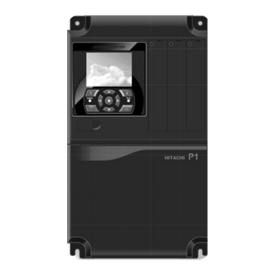
- Page 1 HITACHI P1 BASIC INSTRUCTION MANUAL DETROIT HOIST PROGRAM V27+ Detroit Hoist & Crane LLC, Co. 6650 Sterling Drive North, Sterling Height Michigan 48312 +1 586-268-2600 Manual Revision V1.1 Page 1...
- Page 2 Stop Read First! Important! – This manual was created Detroit hoist program version 27 or greater. Please verify the program number before using this manual by navigating to VFD parameter db-02. To navigate to db-02 and check your VFD’s program number follow the steps chart below.
-
Page 3: Table Of Contents
TABLE OF CONTENTS BASIC SPECIFICATIONS ..................................5 POWER CIRCUIT WIRING ..................................6 CONTROL CIRCUIT WIRING ..................................7 CONFIGURING SPEED CONTROL METHOD ............................8 CONFIGURING SPEEDS / FREQUENCIES ..............................9 MULTI-STEP SPEED COMMAND ................................10 ACCELERATION / DECELERATION TIMES ............................. 11 ALTERNATE ACCELERATION / DECELERATION TIMES .......................... - Page 4 VFD CONTROL MODES ..................................32 MANUAL TORQUE BOOST / AUTOMATIC TORQUE BOOST PARAMETERS ..................32 AUTO-TUNING ..................................... 33 MOTOR CONSTANTS.................................... 33 SPEED DEVIATION (CLV) ..................................34 DYNAMIC BRAKING ..................................... 35 OVER-SPEED (CLV) ....................................36 CARRIER FREQUENCY ..................................36 GROUND FAULT PROTECTION ................................36 INPUT PHASE LOSS PROTECTION .................................
-
Page 5: Basic Specifications
Single phase applica�ons must derate VFD to 70% and may require a larger VFD to supply the required motor current. Please contact Detroit Hoist for further informa�on on single phase applica�ons. • 380-480Vac (400v class models P1-*****-H). • 208-240Vac (200v class models P1-*****-L). -
Page 6: Power Circuit Wiring
POWER CIRCUIT WIRING Risk of electric shock! Risk of electric shock! • Before inspecting the inverter, be sure to turn off • Before inspecting the inverter, be sure to turn off the power supply and wait for more than 10 or 15 the power supply and wait for more than 10 or 15 minutes depending on the invertor model minutes depending on the invertor model... -
Page 7: Control Circuit Wiring
CONTROL CIRCUIT WIRING Below is a basic example of the control circuit for the Hitachi P1 with the DH firmware and may differ from the actual configuration please reference the provided electrical drawing. Please consult Detroit Hoist if you plan to make changes to the control circuit for specific functions to ensure compatibility with the DH firmware. -
Page 8: Configuring Speed Control Method
RS485 / Ezcom communication terminals. Used for Modbus or Ezcom SN, SP communication. Shielded twisted wire required and grounding of shield. RS485 / Ezcom communication termination resistor. Used on the last VFD of the communication circuit by installing jumper between RP and SN. 24v power supply Can be used for adding external 24v power supply and switching the P.SEL dip P+, P-... -
Page 9: Configuring Speeds / Frequencies
CONFIGURING SPEEDS / FREQUENCIES Speed / frequency values are stored as whole numbers (example is 15.25 Hz = 1525). Use the chart below to configure the speeds / frequencies for the configured speed control method. If operating at frequencies below or at 5hz for an extended amount of time an external motor cooling device may be required to prevent motor overheating. -
Page 10: Multi-Step Speed Command
MULTI-STEP SPEED COMMAND Multi-Step speed command can be configured up to 16 speeds. Only use multi-step speed command when speed control greater than 3-steps is required. In the multi-step speed command, 4 inputs as a binary combination of 0 (OFF) and 1 (ON) will determine the command frequency, reference the chart below for configuring the steps and speeds. -
Page 11: Acceleration / Deceleration Times
ACCELERATION / DECELERATION TIMES When adjusting the deceleration times be sure to check the hook block limit for over travel. If over travel occurs either lower the deceleration time or adjust the limit zones. Changing the acceleration time to a shorter time can cause a E01 over-current or E05 over-load fault /trip, if this occurs due to a short acceleration time increase the acceleration time and test again. -
Page 12: Micro-Speed Function
MICRO-SPEED FUNCTION Micro-speed is designed to temporarily restrict the speed of the hoist to a lower speed and to prevent high speed operations until the function is released. The micro-speed function can be configured two ways. 2-STEP MAINTAINED MODE – This mode will switch to a 2-Step maintained speed set. This is helpful where the micro-speeds need to be specific. -
Page 13: Auto-Speed 90Hz Function
AUTO-SPEED 90HZ FUNCTION The auto-speed function will allow the VFD to increase the high speed to 90Hz when there is an empty hook or a light load. You can set this function for automatic or for input activation. The auto-speed function is not available when using 0-10V/4-20mA speed control methods, when micro-speed is active, and or when in tandem mode. -
Page 14: 125% Field Load Testing / Over-Weight Bypass
125% FIELD LOAD TESTING / OVER-WEIGHT BYPASS Each hoist is factory load tested prior to shipment. If a field load test is required, you will need to bypass the over-weight signal. To bypass the over-weight signal, locate the bypass terminal knife disconnect it should be labeled “BPS” (use images below as reference) and pull the yellow/orange tab to open. -
Page 15: Hoist Over-Weight Function
HOIST OVER-WEIGHT FUNCTION The VFD is setup to use the output current to the motor as the over-weight function. The VFD uses (2) over-weight current parameters. Over-weight (1) is when operating less than or equal to the low-speed frequency and over-weight (2) is when operating above low-speed frequency. -
Page 16: Setting Hoist Over-Weight
SETTING HOIST OVER-WEIGHT Each hoist’s over-weight settings will be set at the factory prior to shipment. In some cases, field adjustments may be required. Use the step chart below to set the hoist’s over-weight settings. NOTE – If you are setting the alternative over-weight parameters use steps 6A and 7A Step Instruction Locate the terminal knife disconnect labeled “BPS”... -
Page 17: Configuring An Outut For Fault Signal
CONFIGURING AN OUTUT FOR FAULT SIGNAL The VFD will come from Detroit Hoist with output 16 (dry contact) already configured for fault alarm signal. If you need to switch the fault alarm signal to a different output, use the chart below. Function Parameters Value... -
Page 18: Electronic Motor Thermal Protection
ELECTRONIC MOTOR THERMAL PROTECTION The VFD has a built-in electronic motor thermal protection function and is configured for constant torque loading. When the output current exceeds the value in bC110 for a calculated time based on frequency, time and a reduction ratio. The electronic thermal protection function also has the ability to save the current data and calculate it based on output current and time. -
Page 19: Shock-Load Prevention / Detection (Clv)
SHOCK-LOAD PREVENTION / DETECTION (CLV) Shock-Load prevention / detection is only valid while operating in closed loop vector mode (AA121 = 10). Shock-Load Prevention – When the VFD reaches a constant speed above the low-speed frequency setting, the VFD will monitor the required torque and set the forward driving torque limit to the required torque + a torque padder value. -
Page 20: Motor Brake Parameters
MOTOR BRAKE PARAMETERS While operating in closed loop vector mode (AA121 = 10) the motor brake release and set frequencies are controlled automatically and typically do not require adjustment. When operating in open loop mode (AA121 = 1 thru 9) the motor brake release and set frequencies are controlled by parameters that can be adjusted but typically do not require adjustment. -
Page 21: Encoder-Based Operational Hook Block Limits (Clv)
ENCODER-BASED OPERATIONAL HOOK BLOCK LIMITS (CLV) The VFD has the capability to utilize the motor encoder to create digital upper and lower operational hook block limits. This is done with the use of the encoder from the motor while operating in closed loop vector control only (AA121 = 10) and with the encoder- based limits enabled (UE-33 = 1 or 2). -
Page 22: Setting Encoder-Based Limits (Clv)
SETTING ENCODER-BASED LIMITS (CLV) Use the step chart below to set the encoder-based limits. If using switches from the factory use the image below of the blue terminal knife disconnect as reference. Step Instruction Verify the encoder-based limits are enabled by navigating to VFD parameter UE-33 and verifying the value is set to 1 or 2. -
Page 23: Output Signal For Encoder Limits (Clv)
OUTPUT SIGNAL FOR ENCODER LIMITS (CLV) When using the encoder-based limits it is possible to configure available digital outputs for upper and lower limit indication outputs. Use the chart below. A separate external 24vdc supply is required to be added to power the additional outputs. -
Page 24: Encoder Parameters (Clv)
In most applications the encoder will terminate at the main body digital input terminals and the parameters with Main Body will apply. In some special cases an external feedback card will be installed and the parameters with P1-FB will apply. In the case of the P1-FB card CA-90 will need to = 00: disabled. -
Page 25: Load Float (Clv)
LOAD FLOAT (CLV) Load float is term used in closed loop vector control where the VFD can hold a load at 0hz / 0 speed without the use of the motor brake. This function is available when operating in closed loop mode (AA121 = 10) and will greatly increase the life of the motor brake by only using it as a holding/parking brake and not a dynamic brake in normal operation. -
Page 26: Motor Brake Slip Detection (Clv)
MOTOR BRAKE SLIP DETECTION (CLV) Motor brake slip detection is safety check feature that checks to make sure the motor brake can hold the suspended load at the end of each lift cycle prior to removing complete power from the motor. This is safety check feature is only available when operating in closed loop vector control only (AA121 = 10). -
Page 27: Tandem Hoist Ezcom (Speed / Command / Status Syncing)
TANDEM HOIST EZCOM (SPEED / COMMAND / STATUS SYNCING) Tandem hoist EZCOM can be used when 2 hoists are used in tandem operation and require the frequency, hook limit status, command status, and fault status to sync between each hoist. The VFD’s will need to be configured to communicate between each other and the internal logic activated. -
Page 28: Ezcom Setup Guide
EZCOM SETUP GUIDE Step Instruction Configure the VFD’s parameters using the EZCOM parameter chart. Most of the parameters should already be configured and only the ones highlighted in yellow should need to be changed. Power down both VFD’s and connect the 2-wire shielded cable to the corresponding SN & SP terminals as shown in the EZCOM circuit wiring example on the next page. -
Page 29: Ezcom Circuit Wiring
EZCOM CIRCUIT WIRING EZCOM wiring example circuit. Make sure the BVFD has the RS485 termination jumper installed. Page 29... -
Page 30: Hook Block Syncing / Pulse Train Position Command (Clv)
HOW IT WORKS – The VFD’s use the SN/SP RS485 terminals to send frequency reference, drive status, and command status Modbus registers values between each other. The VFD’s also required the external encoder feedback card (P1-FB) connected. The main hoist will send a 1:1 pulse train from the encoder card to the pulse train input on the follower encoder card. -
Page 31: Pulse Train Position Command Wiring Example (Clv)
PULSE TRAIN POSITION COMMAND WIRING EXAMPLE (CLV) The external encoder card P1-FB will need to be installed in the center option card slot #2 on both VFD’s. Page 31... -
Page 32: Vfd Control Modes
VFD CONTROL MODES If you need to change the VFD control mode for testing, troubleshooting, or changing an open loop hoist to closed loop reference the parameter chart below. Only choose the options provided below that are verified to be compatible with the DH firmware. NOTE –... -
Page 33: Auto-Tuning
AUTO-TUNING Field auto-tuning is generally not required. The VFD will be configured from the factory for the connected motor. If field auto-tuning is required, please use the step chart below. NOTE – The E-stop / maximum upper limit will retain function to prevent over-travel into the frame. The VFD will automatically control the AL relay output for brake release command during auto-tuning. -
Page 34: Speed Deviation (Clv)
SPEED DEVIATION (CLV) The speed deviation error detection function judges that the deviation is excessive if the deviation between the frequency command and the feedback speed becomes large. Speed deviation is the difference between [dA-12] Output frequency monitor and [dA-08] detected frequency monitor. -
Page 35: Dynamic Braking
DYNAMIC BRAKING The dynamic braking is used to electronically brake the motor during deceleration. Dynamic braking required the use of a braking resistor or a regenerative converter. The parameters below only apply when using a resistor. Load-Brake – The internal load-brake absorbs 99% of the dynamic braking. The dynamic braking usage ratio should be set to 3% to detect when the load-brake becomes worn, and maintenance is required. -
Page 36: Over-Speed (Clv)
OVER-SPEED (CLV) The over-speed error detection function judges that the speed is excessive if the feedback speed exceeds the over-speed level. Whether the speed is excessive is determined according to the feedback frequency displayed on [dA-08] Detected frequency monitor. When the speed has exceeded [bb-80] Over-speed error detection level and [bb-81] Over-speed error detection time has elapsed, it is judged as an over-speed error. -
Page 37: Input Phase Loss Protection
INPUT PHASE LOSS PROTECTION When [bb-65] input phase loss selection is set to 01, when a missing phase is detected in input line, the inverter turns OFF its output. This protection function is used to prevent system failure due to unstable motor operation when a phase loss occurs by breakage of the input power cable. -
Page 38: Input Power Supply Over-Voltage Protection
INPUT POWER SUPPLY OVER-VOLTAGE PROTECTION This function will output an error [E015] when the P-N voltage exceeds the voltage level set in the incoming overvoltage level selection [bb-62] for 100 seconds continuously due to incoming voltage. Function Parameter Example Value 0 = warning Power supply over-voltage error selection bb-61... -
Page 39: Monitor Digital Inputs
MONITOR DIGITAL INPUTS The Hitachi VFD’s have a monitor function that will display the status of the 24vdc digital inputs 1 thru 9 & A, B. Unlike the WJ200 the P1 has a GUI screen and supports up to (3) monitors on the main screen. By default, the digital input monitor should be located on the bottom of the main screen on power up. -
Page 40: Monitor Parameters
MONITOR PARAMETERS Monitor Parameter Brief Description Output Frequency dA-01 The commanded output frequency. Output Current dA-02 Displays the output current to the motor. Actual Rotation Direction dA-03 Output rotation direction (f = forward / r = reverse) Encoder Detected Speed dA-08 Displays the detected speed from the encoder Output Torque... -
Page 41: Troubleshooting E50 Fault
TROUBLESHOOTING E50 FAULT WHAT IS AN E50 FAULT - An E50 fault is a brake slip detection fault. This will occur when a brake slip is detected, and the next brake slip detection test has passed usually when a load is removed or on the ground. This fault is used to alert and track that a brake slip has been detected and the motor brake should be inspected immediately before using the hoist again. -
Page 42: Troubleshooting E51 Fault
TROUBLESHOOTING E51 FAULT WHAT IS AN E51 FAULT - An E51 fault is a motor torque proving fault. The motor responded with less than the anticipated motor current. HOW IS AN E51 FAULT DETERMINED – When the VFD is operating in closed loop vector control only (AA121 = 10) at the start of a lift cycle the VFD applies a calculated output torque to the motor and allows a specific amount of time UE-32 for the motor to respond with the motor current. -
Page 43: Troubleshooting E52 Fault
TROUBLESHOOTING E52 FAULT WHAT IS AN E52 FAULT - An E52 fault is a speed deviation fault. The encoder detected speed deviated from the output commanded set-frequency. HOW IS AN E52 FAULT DETERMINED – When the VFD is operating in closed loop vector control only (AA121 = 10) the VFD is constantly comparing the detected frequency from the encoder to the commanded frequency while running. -
Page 44: Troubleshooting E53 Fault
TROUBLESHOOTING E53 FAULT WHAT IS AN E53 FAULT - An E53 fault is a over-torque fault. HOW IS AN E53 FAULT DETERMINED – When the VFD is operating in a control mode of (AA121 = 8, 9, or 10) the VFD will use the torque monitor to determine if the output torque becomes greater than the values in over-torque level parameters CE120 –... -
Page 45: Troubleshooting E054 Fault
TROUBLESHOOTING E054 FAULT WHAT IS AN E54 FAULT - An E54 fault is a shock-load detection fault. HOW IS AN E54 FAULT DETERMINED –When the VFD reaches a constant speed above the low-speed frequency setting, the VFD will monitor the required torque and set the forward driving torque limit to the required torque + a torque padder value. If the required torque changes rapidly the torque limit will react and the VFD will trip with an E54 fault. -
Page 46: Troubleshooting E001 / E005 / E039 Faults
TROUBLESHOOTING E001 / E005 / E039 FAULTS WHAT IS AN E001, E005, and E039 FAULT – The 3 faults are all over-current type faults. • If opera�ng in closed loop AA121 = 10 then check the encoder sha� collar is �ght on the sha� and the encoder tether is secure. -
Page 47: Troubleshooting E007 Fault
TROUBLESHOOTING E007 FAULT WHAT IS AN E007 FAULT – An E007 fault is a dc-bus over-voltage fault. • Check the dynamic braking resistor circuit. Check that the resistor is connected to the correct terminals RB & P+. Check if the resistor is open using a mul�meter. -
Page 48: Troubleshooting E016 Fault
TROUBLESHOOTING E016 FAULT WHAT IS AN E016 FAULT – An E016 fault is an instantaneous power failure fault. When the power is removed and restored within a very short period the VFD will detect that as an instantaneous power failure and will fault to protect the VFD and motor. •... -
Page 49: Troubleshooting Blank Screen / Display
TROUBLESHOOTING BLANK SCREEN / DISPLAY If the VFD’s screen / display is blank it usually means the internal 24v power supply is shorted or damaged. In most cases if a connected circuit is causing the short, disconnecting that circuit will restore 24v power to the screen / display. •... -
Page 50: Fault / Error Codes Description
FAULT / ERROR CODES DESCRIPTION Fault / Error Code Description E001 Over-current error E005 / E039 Electronic thermal overload error (motor current > bC110) E006 Dynamic braking resistor over used error E007 DC-Bus over-voltage error E008 / E011 Memory error / CPU error E009 Undervoltage error E010... - Page 51 Option card slot 3 connection error E090 – E096 STO path error / FS option error E100 Encoder disconnection error when using P1-FB option card Position control range error E104 The encoder position data exceeded (268435455 | -268435455) pulses E105...
-
Page 52: View Fault History
VIEW FAULT HISTORY To view the fault history, use the step chart below. Step Instruction Power on the VFD. Press the left arrow button 2 times to view the fault history list. Use the up and down arrow buttons to scroll through the fault history list and use the center dot button to select the fault and view information as in date / time / fault / status / output current / dc-buss / ext. -
Page 53: Clearing Fault History
CLEARING FAULT HISTORY To clear the fault history, use the step chart below. Step Instruction Power on the VFD. Press the #1 button one time to view the menu screen. Use the arrow buttons to highlight “SCROLL MODE” and press the center dot button to enter the “SCROLL MENU”. Use the arrow buttons to scroll down to “U:Set-up, PDN”... -
Page 54: Using The Keypad
USING THE KEYPAD Page 54... - Page 55 Page 55...
- Page 56 Page 56...
- Page 57 Page 57...
- Page 58 Page 58...
- Page 59 Page 59...
- Page 60 Page 60...
- Page 61 Page 61...
- Page 62 Page 62...
- Page 63 Page 63...
- Page 64 Page 64...
- Page 65 REVISIONS Version Date Changes / Updates 12/10/2021 Initial release 1/6/2022 Fixed typo on Ezcom set-up guide. Added Limit To 1 Speed input configuration. Page 65...