Hitachi WJ200 Series Instruction Manual
Wj200 series single-phase input 200v class three-phase input 200v class three-phase input 400v class
Hide thumbs
Also See for WJ200 Series:
- Quick reference manual (131 pages) ,
- Instruction manual (30 pages) ,
- Installation manual (20 pages)
Table of Contents
Quick Links
See also:
Installation Manual, Quick Reference Manual
Table of Contents
Troubleshooting

Related Manuals for Hitachi WJ200 Series


Summary of Contents for Hitachi WJ200 Series
- Page 1 WJ200 Series Inverter Instruction Manual • Single-phase Input 200V class • Three-phase Input 200V class • Three-phase Input 400V class Manual Number: NT325X After read this manual, Keep it handy for future reference. May 2010 Hitachi Industrial Equipment Systems Co., Ltd.
-
Page 2: Safety Messages
Safety Messages For the best results with the WJ200 Series inverter, carefully read this manual and all of the warning labels attached to the inverter before installing and operating it, and follow the instructions exactly. Keep this manual handy for quick reference. Definitions and Symbols A safety instruction (message) includes a “Safety Alert Symbol”... - Page 3 WJ200 series equipment. CAUTION: Proper grounds, disconnecting devices and other safety devices and their location are the responsibility of the user and are not provided by Hitachi Industrial Equipment Systems Co., Ltd. CAUTION: Be sure to connect a motor thermal disconnect switch or overload device to the WJ200 series controller to assure that the inverter will shut down in the event of an overload or an overheated motor.
- Page 4 WARNING: Rotating shafts and above-ground electrical potentials can be hazardous. Therefore, it is strongly recommended that all electrical work conform to the National Electrical Codes and local regulations. Installation, alignment and maintenance should be performed only by qualified personnel. CAUTION: a) Class I motor must be connected to earth ground via low resistive path (<0.1Ω) b) Any motor used must be of a suitable rating.
-
Page 5: Index To Warnings And Cautions In This Manual
Index to Warnings and Cautions in This Manual Cautions and Warnings for Orientation and Mounting Procedures HIGH VOLTAGE: Hazard of electrical shock. Disconnect incoming power before …2-3 working on this control. Wait five (5) minutes before removing the front cover. Hazard of electrical shock. - Page 6 Wiring – Warnings for Electrical Practice and Wire Specifications WARNING: “USE 60/75°C Cu wire only” or equivalent. For models WJ200-001L, -002L, …2-18 -004L, -007L, -015S, -022S, -004H, -007H, -015H, -022H and -030H. WARNING: “USE 75°C Cu wire only” or equivalent. For models WJ200-001S, -002S, …2-18 -004S, -007S, -015L, -022L, -037L, -055L, -075L, -110L, -150L, -037H, -040H, -055H, -075H, -110H and -150H.
- Page 7 Wiring – Cautions for Electrical Practice CAUTION: Fasten the screws with the specified fastening torque in the table … 2-18 below. Check for any loosening of screws. Otherwise, there is the danger of fire. CAUTION: Be sure that the input voltage matches the inverter specifications; …...
- Page 8 CAUTION: Remarks for using ground fault interrupter breakers in the main … 2-20 power supply: Adjustable frequency inverter with integrated CE-filters and shielded (screened) motor cables have a higher leakage current toward earth GND. Especially at the moment of switching ON this can cause an inadvertent trip of ground fault interrupters.
- Page 9 viii Warnings for Configuring Drive Parameters WARNING: When parameter b012, level of electronic thermal setting, is set to … 3-34 motor FLA rating (Full Load Ampere nameplate rating), the inverter provides solid state motor overload protection at 115% of motor FLA or equivalent. If parameter B012 exceeds the motor FLA rating, the motor may overheat and damaged.
- Page 10 WARNING: Be sure not to touch the inside of the energized inverter or to put any … conductive object into it. Otherwise, there is a danger of electric shock and/or fire. WARNING: If power is turned ON when the Run command is already active, the …...
-
Page 11: General Warnings And Cautions
Warnings and Cautions for Troubleshooting and Maintenance WARNING: Wait at least five (5) minutes after turning OFF the input power … supply before performing maintenance or an inspection. Otherwise, there is the danger of electric shock. WARNING: Make sure that only qualified personnel will perform maintenance, …... - Page 12 CAUTION: Do not stop operation by switching OFF electromagnetic contactors on the primary or secondary side of the inverter. Ground fault interrupter Power Inverter Input L1, L2, L3 U, V, W Motor When there has been a sudden power failure while an operation instruction is active, then the unit may restart operation automatically after the power failure has ended.
- Page 13 CAUTION: EFFECTS OF POWER DISTRIBUTION SYSTEM ON INVERTER In the case below involving a general-purpose inverter, a large peak current can flow on the power supply side, sometimes destroying the converter module: The unbalance factor of the power supply is 3% or higher. the power supply capacity is at least 10 times greater than the inverter capacity (or the power supply capacity is 500kVA or more).
- Page 14 xiii CAUTION: In all the instrumentations in this manual, covers and safety devices are occasionally removed to describe the details. While operating the product, make sure that the covers and safety devices are placed as they were specified originally and operate it according to the instruction manual.
- Page 15 Terminal symbols and Screw size Required Inverter Model Screw Size Wire range Torque (N-m) WJ200-001S WJ200-002S M3.5 AWG16 (1.3mm WJ200-004S WJ200-007S AWG12 (3.3mm WJ200-015S AWG10 (5.3mm WJ200-022S WJ200-001L WJ200-002L M3.5 AWG16 (1.3mm WJ200-004L WJ200-007L WJ200-015L AWG14 (2.1mm WJ200-022L AWG12 (3.3mm WJ200-037L AWG10 (5.3mm WJ200-055L...
- Page 16 Fuse Sizes The inverter shall be connected with a UL Listed Cartridge Nonrenewable fuse, rated 600Vac with the current ratings as shown in the table below. Inverter Model Type Rating WJ200-001S WJ200-002S 10A, AIC 200kA WJ200-004S WJ200-007S 15A, AIC 200kA WJ200-015S 30A, AIC 200kA WJ200-022S...
-
Page 17: Table Of Contents
Table of Contents Safety Messages Hazardous High Voltage ....................... i General Precautions – Read These First! ................. ii Index to Warnings and Cautions in This Manual ..............iv General Warnings and Cautions ....................x UL Cautions, Warnings and Instructions ................xiii Circuit Breaker and Fuse Sizes .................... -
Page 18: Table Of Contents
xvii Chapter 4: Operations and Monitoring Introduction ..........................4-2 Connecting to PLCs and Other Devices ................4-4 Control Logic Signal Specifications ..................4-6 Intelligent Terminal Listing ....................4-10 Using Intelligent Input Terminals ..................4-12 Using Intelligent Output Terminals ................... 4-51 Analog Input Operation ....................... - Page 19 xviii Revisions Revision History Table Date of Operation Revision Comments Issue Manual No.
- Page 20 Fax: +852-2735-6793 NOTE: To receive technical support for the Hitachi inverter you purchased, contact the Hitachi inverter dealer from whom you purchased the unit, or the sales office or factory contact listed above. Please be prepared to provide the following inverter...
-
Page 21: Introduction
1−1 Getting Started In This Chapter… page - Introduction ..................2 - WJ200 Inverter Specifications ............4 - Introduction to Variable-Frequency Drives ........18 - Frequently Asked Questions ............23... - Page 22 The housing footprint is exceptionally small, given the size of the corresponding motor. The Hitachi WJ200 product line includes more than a dozen inverter models to cover motor sizes from 1/8 horsepower to 20 horsepower, in either 240VAC or 480VAC power input versions.
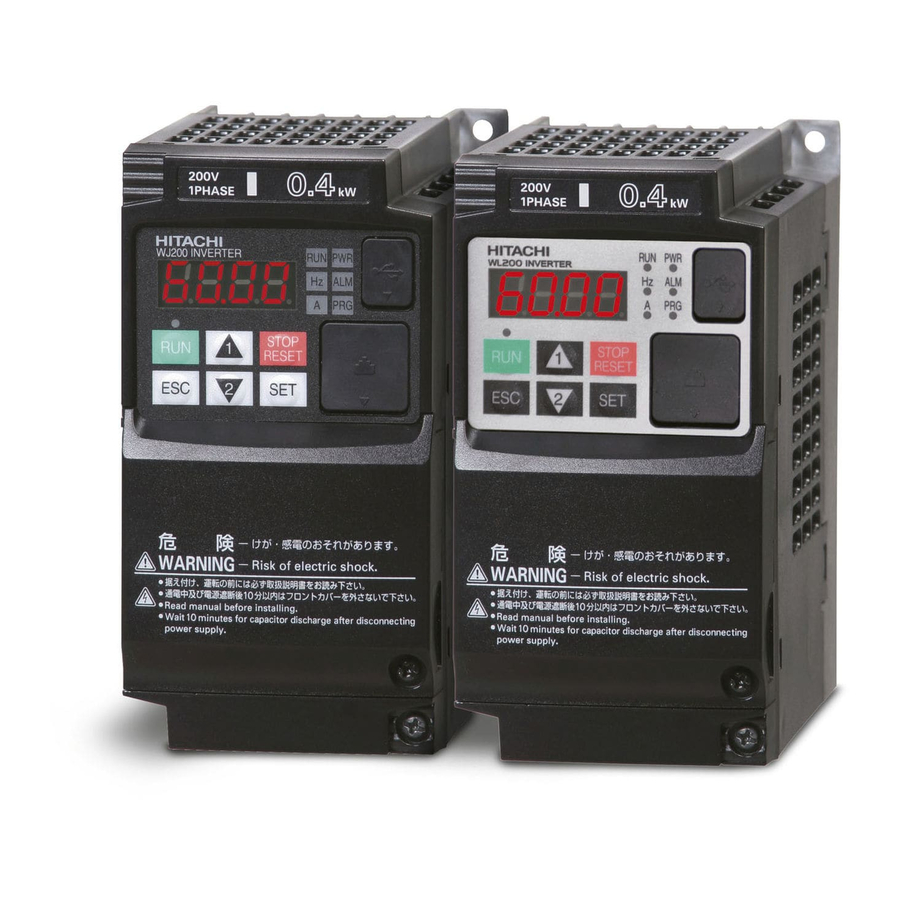
- Page 23 1−3 Inverter Specification Label The Hitachi WJ200 inverters have product labels located on the right side of the housing, as pictured below. Be sure to verify that the specifications on the labels match your power source, and application safety requirements.
-
Page 24: Wj200 Inverter Specifications
1−4 WJ200 Inverter Specifications Model-specific tables for 200V and 400V class inverters The following tables are specific to WJ200 inverters for the 200V and 400V class model groups. Note that “General Specifications” on page in this chapter apply to both voltage class groups. - Page 25 (for Low Voltage Directive). Note6: At the rated voltage when using a Hitachi standard 3-phase, 4-pole motor. Note7: The braking torque via capacitive feedback is the average deceleration torque at the shortest deceleration (stopping from 50/60Hz as indicated). It is not continuous regenerative braking torque.
- Page 26 1−6 WJ200 Inverter Specifications, continued… Item Three-phase 200V class Specifications WJ200 inverters, 200V models 001LF 002LF 004LF 007LF 015LF 022LF Applicable motor size 0.75 0.75 Rated capacity (kVA) 200V 240V Three-phase: 200V-15% to 240V +10%, 50/60Hz ±5% Rated input voltage Rated output voltage *3 Three-phase: 200 to 240V (proportional to input voltage) Rated output current (A)
- Page 27 1−7 WJ200 Inverter Specifications, continued… Item Three-phase 400V class Specifications WJ200 inverters, 400V models 004HF 007HF 015HF 022HF 030HF 040HF Applicable motor size 0.75 0.75 Rated capacity (kVA) 380V 480V Three-phase: 400V-15% to 480V +10%, 50/60Hz ±5% Rated input voltage Rated output voltage *3 Three-phase: 400 to 480V (proportional to input voltage) Rated output current (A)
-
Page 28: General Specifications
1−8 General Specifications The following table applies to all WJ200 inverters. Item General Specifications Protective housing *1 IP20 Control method Sinusoidal Pulse Width Modulation (PWM) control Carrier frequency 2kHz to 15kHz (derating required depending on the model) Output frequency range *4 0.1 to 400Hz Frequency accuracy Digital command: ±0.01% of the maximum frequency... - Page 29 1−9 Item General Specifications Output Intelligent output RUN (run signal), FA1~FA5 (frequency arrival signal), OL,OL2 (overload advance notice signal), OD (PID deviation error signal), AL (alarm signal), signal terminal OTQ (over/under torque threshold), UV (under-voltage), TRQ (torque limit signal), RNT (run time expired), ONT (power ON time expired), THM 48 functions assignable (thermal warning), BRK (brake release), BER (brake error), ZS (0Hz detection), DSE (speed deviation excessive), POK (positioning completion),...
- Page 30 1−10 Signal Ratings Detailed ratings are in “Control Logic Signal Specifications” in chapter 4. Signal / Contact Ratings Built-in power for inputs 24VDC, 100mA maximum Discrete logic inputs 27VDC maximum Discrete logic outputs 50mA maximum ON state current, 27 VDC maximum OFF state voltage Analog output 10bit / 0 to 10VDC, 2mA Analog input, current...
- Page 31 1−11 Derating Curves The maximum available inverter current output is limited by the carrier frequency and ambient temperature.. Choosing a higher carrier frequency tends to decrease audible noise, but it also increases the internal heating of the inverter, thus decreasing (derating) the maximum current output capability.
- Page 32 1−12 The following table shows which models need derating. 1-ph 200V class Need 3-ph 200V class Need 3-ph 400V class Need derating derating derating WJ200-001S WJ200-001L WJ200-004H - - WJ200-002S WJ200-002L WJ200-007H - WJ200-004S WJ200-004L WJ200-015H - WJ200-007S WJ200-007L WJ200-022H -...
- Page 33 1−13 Derating curves, continued... Models need derating WJ200-002L HD(1.6A) ND(1.9A) 40℃ individual 40℃ individual 40℃ side-by-side 40℃ side-by-side Output current (A) 8 10 12 8 10 12 14 Carrier frequency (kHz) Carrier frequency (kHz) WJ200-004S HD(3.0A) ND(3.5A) Output current (A) 8 10 12 8 10 12 14 Carrier frequency (kHz)
- Page 34 1−14 Derating curves, continued... WJ200-004H HD(1.8A) ND(2.1A) 40℃ individual 40℃ side-by-side 40℃ individual 40℃ side-by-side Output 50℃ individual current (A) 1.5 8 10 12 8 10 12 14 Carrier frequency (kHz) Carrier frequency (kHz) HD(5.0A) ND(6.0A) WJ200-007S 40℃ individual 40℃ individual 40℃...
- Page 35 1−15 Derating curves, continued... WJ200-037L HD(17.5A) ND(19.6A) Output current (A) 8 10 12 8 10 12 14 Carrier frequency (kHz) rrier frequency (kH WJ200-040H HD(9.2A) ND(11.1A) 40℃ individual 40℃ side-by-side 40℃ individual 40℃ side-by-side Output current (A) 8 10 12 8 10 12 14 Carrier frequency (kHz) Carrier frequency (kHz)
- Page 36 1−16 Derating curves, continued... HD(47.0A) ND(56.0A) WJ200-075H 40℃ individual 40℃ side-by-side Output current (A) 8 10 12 14 8 10 12 Carrier frequency (kHz) Carrier frequency (kHz) HD(18.0A) ND(23.0A) WJ200-110L 40℃ individual 40℃ side-by-side 50℃ individual 40℃ indivi dual 50℃ indivi dual Output current...
- Page 37 1−17 Derating curves, continued... HD(60.0A) ND(69.0A) WJ200-150L Output 50℃ individual current (A) 40℃ side-by-side 50℃ individual 40℃ side-by-side 8 10 12 16kH 8 10 12 14 Carrier frequency (kHz) Carrier frequency (kHz) WJ200-150H HD(31.0A) ND(38.0A) 50℃ individual Output 40℃ side-by-side 50℃...
-
Page 38: Introduction To Variable-Frequency Drives
Introduction to Variable-Frequency Drives The Purpose of Motor Speed Control for Industry Hitachi inverters provide speed control for 3-phase AC induction motors. You connect AC power to the inverter, and connect the inverter to the motor. Many applications benefit from a motor with variable speed, in several ways: •... - Page 39 Inverter Input and Three-phase Power The Hitachi WJ200 Series of inverters includes two sub-groups: the 200V class and the 400V class inverters. The drive described in this manual may be used in either the United States or Europe, although the exact voltage level for commercial power may be slightly different from country to country.
- Page 40 The Hitachi inverter is a rugged and reliable device. The intention is for the inverter to assume the role of controlling power to the motor during all normal operations.
- Page 41 “Introduction” on page 5-2 and “Dynamic Braking” on page 5-5 for more information). For loads that continuously overhaul the motor for extended periods of time, the WJ200 may not be suitable (contact your Hitachi distributor). The inverter parameters include acceleration and deceleration, which you can set to match the needs of the application.
- Page 42 1−22 Velocity Profiles The WJ200 inverter is capable of sophisticated Speed Set speed speed control. A graphical representation of that capability will help understand Accel Decel configure the associated parameters. This manual makes use of the velocity profile graph used in industry (shown at right). In the Velocity Profile acceleration example,...
-
Page 43: Frequently Asked Questions
1−23 Frequently Asked Questions Q. What is the main advantage in using an inverter to drive a motor, compared to alternative solutions? A. An inverter can vary the motor speed with very little loss of efficiency, unlike mechanical or hydraulic speed control solutions. The resulting energy savings usually pays for the inverter in a relatively short time. - Page 44 Q. How many poles should the motor have? A. Hitachi inverters can be configured to operate motors with 2, 4, 6, or 8 poles. The greater the number of the poles, the slower the top motor speed will be, but it will have higher torque at the base speed.
- Page 45 This is a physics question that may be answered either empirically or through extensive calculations. Q. Several options related to electrical noise suppression are available for the Hitachi inverters. How can I know if my application require any of these options? A.
- Page 46 2−1 Inverter Mounting and Installation In This Chapter… page - Orientation to Inverter Features ............. 2 - Basic System Description ............... 4 - Step-by-Step Basic Installation ............6 - Powerup Test .................. 23 - Using the Front Panel Keypad ............25...
-
Page 47: Orientation To Inverter Features
2−2 Orientation to Inverter Features Unpacking and Inspection Please take a few moments to unpack your new WJ200 inverter and perform these steps: Look for any damage that may have occurred during transportation. Verify the contents of the box include: a. - Page 48 2−3 Power Wiring Access – First, ensure no power source is connected to the inverter. If power has been connected, verify that the Power LED is OFF and then wait five minutes after power down to proceed. After removing the terminal cover and front housing cover, the housing partitions that cover the power and motor wiring exits will be able to slide upward as shown below.
-
Page 49: Basic System Description
2−4 Basic System Description A motor control system will obviously include a motor and inverter, as well as a circuit breaker or fuses for safety. If you are connecting a motor to the inverter on a test bench just to get started, that’s all you may need for now. But a system can also have a variety of additional components. - Page 50 2−5 WARNING: In the cases below involving a general-purpose inverter, a large peak current can flow on the power supply side, sometimes destroying the converter module: 1. The unbalance factor of the power supply is 3% or higher. 2. The power supply capacity is at least 10 times greater than the inverter capacity (or the power supply capacity is 500kVA or more).
-
Page 51: Step-By-Step Basic Installation
2−6 Step-by-Step Basic Installation This section will guide you through the following basic steps of installation: Step Activity Page Choose a mounting location in compliance with the Warnings and Cautions. See NOTE below. Check the mounting location for adequate ventilation Cover the inverter’s ventilation openings to prevent debris from entering. - Page 52 2−7 Choosing a Mounting Location Step 1: Study the following caution messages associated with mounting the inverter. This is the time when mistakes are most likely to occur that will result in expensive rework, equipment damage, or personal injury. CAUTION: Be sure to install the unit on flame-resistant material such as steel plate. Otherwise, there is the danger of fire.
- Page 53 2−8 Ensure Adequate Ventilation Step 2: To summarize the caution messages – you will need to find a solid, non-flammable, vertical surface that is in a relatively clean and dry environment. In order to ensure enough room for air circulation around the inverter to aid in cooling, it is recommended to maintain the specified clearance and the inverter specified in the below diagram.
- Page 54 2−9 Check Inverter Dimensions Step 4: Locate the applicable drawing on the following pages for your inverter. Dimensions are given in millimeters (inches) format. Power Type W (mm) H (mm) D (mm) D1 (mm) Single-phase 200V WJ200-001SF 13.5 WJ200-002SF WJ200-004SF 122.5 3-phase 200V WJ200-001LF...
- Page 55 2−10 Dimensional drawings, continued… Power Type W (mm) H (mm) D (mm) D1 (mm) Single-phase 200V WJ200-007SF WJ200-015SF WJ200-022SF 170.5 3-phase 200V WJ200-015LF WJ200-022LF 3-phase 400V WJ200-004HF 143.5 WJ200-007HF WJ200-015HF WJ200-022HF 170.5 WJ200-030HF...
- Page 56 2−11 Dimensional drawings, continued… Power Type W (mm) H (mm) D (mm) D1 (mm) 3-phase 200V WJ200-037LF 170.5 3-phase 400V WJ200-040HF...
- Page 57 2−12 Dimensional drawings, continued… Power Type W (mm) H (mm) D (mm) D1 (mm) 3-phase 200V WJ200-055LF WJ200-075LF 73.3 3-phase 400V WJ200-055HF WJ200-075HF...
- Page 58 2−13 Dimensional drawings, continued… Power Type W (mm) H (mm) D (mm) D1 (mm) 3-phase 200V WJ200-110LF 3-phase 400V WJ200-110HF WJ200-150HF...
- Page 59 2−14 Dimensional drawings, continued… Power Type W (mm) H (mm) D (mm) D1 (mm) 3-phase 200V WJ200-150LF...
- Page 60 2−15 Prepare for Wiring Step 5: It is very important to perform the wiring steps carefully and correctly. Before proceeding, please study the caution and warning message herebelow. WARNING: Use 60/75°C Cu wire only. (for models: WJ200-001L, -002L, -004L, -007L, -015S, -022S, -004H, -007H, -015H, -022H and -030H) WARNING: Use 75°C Cu wire only.
- Page 61 2−16 Determining Wire and Fuse Sizes The maximum motor currents in your application determines the recommended wore size. The following table gives the wire size in AWG. The “Power Lines” column applies to the inverter input power, output wires to the motor, the earth ground connection, and any other components shown in the “Basic System Description”...
- Page 62 2−17 Terminal Dimensions and Torque Specs The terminal screw dimensions for all WJ200 inverters are listed in table below. This information is useful in sizing spade lug or ring lug connectors for wire terminations. WARNING: Tighten the screws with the specified torque in the table below. Check for any loosening of screws.
- Page 63 2−18 Wire the Inverter Input to a Supply Step 6: In this step, you will connect wiring to the input of the inverter. First, you must determine whether the inverter model you have required three-phase power only, or single-phase power only. All models have the same power connection terminals [R/L1], [S/L2], and [T/L3].
- Page 64 2−19 Three-phase 200V 3.7kW Three-phase 400V 4.0kW U/T1 V/T2 W/T3 Chassis Ground (M4) Power input Output to Motor Three-phase 200V 5.5, 7.5kW Three-phase 400V 5.5, 7.5kW R/L1 S/L2 T/L3 U/T1 V/T2 W/T3 PD/+1 Power input Output to Motor...
- Page 65 2−20 Three-phase 200V 11kW Three-phase 400V 11, 15kW R/L1 S/L2 T/L3 U/T1 V/T2 W/T3 PD/+1 Power input Output to Motor Three-phase 200V 15kW R/L1 S/L2 T/L3 U/T1 V/T2 W/T3 PD/+1 Power input Output to Motor NOTE: An inverter powered by a portable power generator may receive a distorted power waveform, overheating the generator.
- Page 66 2−21 CAUTION: Be sure that the input voltage matches the inverter specifications: • Single-phase 200 to 240 V 50/60 Hz (0.1kW~2.2kW) for SF models • Three-phase 200 to 240 V 50/60 Hz (0.1kW~15kW) for LF models • Three-phase 380 to 480 V 50/60Hz (0.4kW~15kW) for HF models CAUTION: Be sure not to power a three-phase-only inverter with single-phase power.
- Page 67 2−22 Wire the Inverter Output to Motor Step 7: The process of motor selection is beyond the scope of this manual. However, it must be an AC induction motor with three phases. It should also come with a chassis ground lug. If the motor does not have three power input leads, stop the installation and verify the motor type.
-
Page 68: Powerup Test
3. Get an introduction to the use of the built-in operator keypad. The powerup test gives you an important starting to ensure a safe and successful application of the Hitachi inverter. We highly recommend performing this test before proceeding to the other chapters in this manual. - Page 69 2−24 Pre-test and Operational Precautions The following instructions apply to the powerup test, or to any time the inverter is powered and operating. Please study the following instructions and messages before proceeding with the powerup test. 1. The power supply must have fusing suitable for the load. Check the fuse size chart presented in Step 5, if necessary.
-
Page 70: Using The Front Panel Keypad
2−25 Using the Front Panel Keypad Please take a moment to familiarize yourself with the keypad layout shown in the figure below. The display is used in programming the inverter’s parameters, as well as monitoring specific parameter values during operation. (1) POWER LED (4) RUN LED (5) Monitor LED [Hz]... - Page 71 2−26 Keys, Modes, and Parameters The purpose of the keypad is to provide a way to change modes and parameters. The term function 8888 applies to both monitoring modes and parameters. These are all accessible through function codes that are primary 4-character codes. The various functions STOP/ RESET are separated into related groups identifiable by the...
- Page 72 2−27 Func. code display : Moves to data display Group "d" Func. code display d001 0.00 d002 Func. code display : Jumps to the next group d104 Group "F" Func. code display Save F001 50.00 F002 50.01 F004 Data display (F001 to F003) Data does not blink because of real time synchronizing : Saves the data in EEPROM and returns to...
- Page 73 2−28 [Setting example] After power ON, changing from 0.00 display to change the b083 (carrier frequency) data. d001 Data of will be shown on the Press [ESC] key to show display after the first power ON the function code 0.00 d001 F001 Press [ESC] key to move on to the function group...
- Page 74 2−29 Selecting Functions and Editing Parameters To prepare to run the motor in the powerup test, this section will show how to configure the necessary parameters: 1. Select the digital operator as the source of motor speed command (A001=02). 2. Select the digital operator as the source of the RUN command (A002=02). 3.
- Page 75 2−30 2. Select the digital operator for RUN Command – Run Key Enable LED To RUN command causes the inverter to accelerate the motor to the selected speed. The Run command can arrive from various sources, including the 8888 control terminals, the Run key on the keypad or the network.
- Page 76 2−31 3. Set the Motor Base Frequency and AVR voltage of the motor – The motor is designed to operate at a specific AC frequency. Most commercial motors are designed for 50/60 Hz operation. First, check the motor specifications. Then follow the steps below to verify the setting or correct it for your motor.
- Page 77 2−32 4. Set the Motor Current – The inverter has thermal overload protection that is designed to protect the inverter and motor from overheating due to an excessive load. The inverter’s uses the motor’s current rating to calculate the time-based heating effect. This protection depends on using correct current rating for your motor.
- Page 78 2−33 5. Set the Number of Motor Poles – The motor’s internal winding arrangement determines its number of magnetic poles. The specification label on the motor usually indicates the number of poles. For proper operation, verify the parameter setting matches the motor poles. Many industrial motors have four poles, corresponding to the default setting in the inverter (H004).
- Page 79 2−34 Monitoring Parameters with the Display After using the keypad for parameter editing, it’s a good idea to switch the inverter from Program Mode 8888 to Monitor Mode. The PRG LED will be OFF, and the Hertz or Ampere LED indicates the display units. For the powerup test, monitor the motor speed STOP/ RESET...
- Page 80 − 2 35 Single-Digit Edit Mode If a target function code or data is far from current data, using the single-digit edit mode makes it quicker. Pressing the up key and down key at the same time leads you to go into the digit-to-digit changing mode. While in Single-digit edit mode (single digit is blinking): : Move cursor to right or set the func.code/data (lowest digit only) : Move cursor to left.
- Page 81 NOTE: Some factory automation devices such as PLCs have alternative Run/Program modes; the device is in either one mode or the other. In the Hitachi inverter, however, Run Mode alternates with Stop Mode, and Program Mode alternates with Monitor Mode.
-
Page 82: Table Of Contents
3−1 Configuring Drive Parameters In This Chapter… page - Choosing a Programming Device ........... 2 - Using the Keypad Devices .............. 3 - “D” Group: Monitoring Functions ..........7 - “F” Group: Main Profile Parameters ..........11 - “A” Group: Standard Functions ........... 12 - “B”... -
Page 83: Choosing A Programming Device
Choosing a Programming Device Introduction Hitachi variable frequency drives (inverters) use the latest electronics technology for getting the right AC waveform to the motor at the right time. The benefits are many, including energy savings and higher machine output or productivity. The flexibility required to handle a broad range of applications has required ever more configurable options and parameters –... -
Page 84: Using The Keypad Devices
3−3 Using the Keypad Devices The WJ200 Series inverter front keypad contains all the elements for both monitoring and programming parameters. The keypad layout is pictured below. All other programming devices for the inverter have a similar key arrangement and function. Power LED Display Units (Hertz / Amperes) LEDs Run LED... - Page 85 3−4 Operational Modes The RUN and PRG LEDs tell just part of the story; STOP Run Mode and Program Modes are independent RESET Stop modes, not opposite modes. In the state diagram to the right, Run alternates with Stop, and Program Mode alternates with Monitor Mode.
- Page 86 3−5 Dual Rating Selection The WJ200 series inverter has Dual Rating, so that it can work in two different types of load condition, Constant torque application and Variable torque application. Select parameter b049 depending on your application. “b” Function Defaults Mode Func.
- Page 87 3−6 When HD is selected, following parameters are not displayed. Func. Func. Name Name code code d009 Torque command monitor C058 Over/under-torque level (FW,RG) d010 Torque bias monitor C059 Output mode of Over/under-torque d012 Torque monitor H001 Auto-tuning selection b040 Torque limit selection H002/H202 Motor constant selection...
-
Page 88: D" Group: Monitoring Functions
3−7 “D” Group: Monitoring Functions You can access important parameter values with the “D” Group monitoring functions, whether the inverter is in Run Mode or Stop Mode. After selecting the function code number for the parameter you want to monitor, press the Function key once to show the value on the display. - Page 89 3−8 “d” Function Func. Mode Units Name Description Edit Code Scaled output frequency Displays output frequency − Hz times D007 monitor constant scaled by the constant in B086. Decimal point indicates range: 0 to 3999 Actual frequency monitor Displays actual frequency, −...
- Page 90 3−9 “d” Function Mode Units Func. Name Description Edit Code DC bus voltage monitor Voltage of inverter internal DC bus, − D102 Range is 0.0 to 999.9 BRD load ratio monitor Usage ratio of integrated brake − d103 chopper, range is 0.0~100.0% Electronic thermal monitor Accumulated value...
- Page 91 3−10 Local Monitoring with keypad connected The WJ200 inverter’s serial port may be connected to an external digital operator. During those times, the inverter keypad keys will not function (except for the Stop key). However, the inverter’s 4-digit display still provides the Monitor Mode function, displaying any of the parameters D001 to D060.
-
Page 92: F" Group: Main Profile Parameters
3−11 “F” Group: Main Profile Parameters The basic frequency (speed) profile is Output frequency defined by parameters contained in the F002 F003 “F” Group as shown to the right. The set running frequency is in Hz, but A004 acceleration deceleration F001 specified in the time duration of the ramp (from zero to maximum frequency,... -
Page 93: A" Group: Standard Functions
3−12 “A” Group: Standard Functions The inverter provides flexibility in how you control Run/Stop operation and set the output frequency (motor speed). It has other control sources that can override the A001 / A002 settings. Parameter A001 sets the source selection for the inverter’s output frequency. - Page 94 3−13 Run Command Source Setting – For parameter A002, the following table provides a further description of each option, and a reference to other page(s) for more information. Code Run Command Source Refer to page(s)… Control terminal – The [FW] or [RV] input terminals control 4-16 Run/Stop operation Keypad Run key –...
- Page 95 3−14 The figure below shows the correlation diagram of all frequency source setting methods and their relative priority. Multi-speed Multi-speed Multi-speed inputs inputs inputs CF1-4,SF1-7 CF1-4,SF1-7 CF1-4,SF1-7 Multi-speed Multi-speed Multi-speed Frequency Frequency Frequency A021-A035 A021-A035 A021-A035 setting setting setting [O]+[OI] [O]+[OI] [O]+[OI] [AT]...
- Page 96 3−15 Basic Parameter Settings These settings affect the most fundamental behavior of the inverter – the outputs to the motor. The frequency of the inverter’s AC output determines the motor speed. You may select from three different sources for the reference speed. During application development you may prefer using the potentiometer, but you may switch to an external source (control terminal setting) in the finished application, for example.
- Page 97 3−16 Analog Input Settings The inverter has the capability to accept an external analog input that can command the output frequency to the motor. Voltage input (0-10 V) and current input (4-20mA) are available on separate terminals ([O] and [OI] respectively). Terminal [L] serves as signal ground for the two analog inputs.
- Page 98 3−17 “A” Function Defaults Func. Mode Name Description Lnitial data Units Code Edit [AT] selection Three options; select codes: − A005 00...Select between [O] and [OI] at [AT] (ON=OI, OFF=O) 02...Select between [O] and [O] input active range start 0.00 A011 external POT at [AT] frequency...
- Page 99 3−18 TIP: The deadband feature is useful in applications that requires a very stable output frequency but use an analog input for the speed reference. Example application: A grinding machine uses a remote potmeter for operator speed input. After a setting change, the grinder maintains a very stable speed to deliver a uniform finished surface.
- Page 100 3−19 Multi-speed and Jog Frequency Setting Multi-speed – The WJ200 inverter has the capability to store and output up to 16 preset frequencies to the motor (A020 to A035). As in traditional motion terminology, we call multi-speed profile this capability. These preset frequencies are selected by means of digital inputs to the inverter.
- Page 101 3−20 (1) Binary operation (“1”=ON) Speed Param. A020 Speed 0 A021 Speed 1 A022 Speed 2 Speed 3 A023 Speed 4 A024 Speed 5 A025 Speed 6 A026 A027 Speed 7 A028 Speed 8 A029 Speed 9 A030 Speed 10 A031 Speed 11 A032...
- Page 102 3−21 Jog Frequency – The jog speed setting is used whenever the Jog command is active. The jog speed setting range is arbitrarily limited to 10 Hz, to provide safety during manual operation. The acceleration to the jog frequency is instantaneous, but you can choose from three modes for the best method for stopping the jog operation.
- Page 103 3−22 Torque Control Algorithms Inverter Torque Control Algorithms The inverter generates the motor output according algorithm selected. V/F control constant torque (V/F-VC) Parameter A044 selects the inverter algorithm A044 for generating the frequency output, as shown in V/F control, variable (1.7) torque the diagram to the right (A244 for 2nd motor).
- Page 104 3−23 Enabling the free V/F characteristics setting function disables the torque boost selection (A041/A241), base frequency setting (A003/A203), and maximum frequency setting (A004/A204) automatically. (The inverter regard the value of free-setting V/F frequency 7 (b112) as the maximum frequency.) Output voltage (V) V7 (b113) V6 (b111) V5 (b109)
- Page 105 3−24 Manual Torque Boost – The Constant Variable Torque algorithms A042 torque boost feature an adjustable = 5 (%) curve. When the motor load has a lot of 100% inertia or starting friction, you may need to increase the low frequency 5% voltage starting torque...
- Page 106 3−25 load is given to the motor automatic torque boost, step by step A047 / A247 Motor speed increases when a load is Decrease the slip compensation gain for given to the motor automatic torque boost, step by step A042 / A242 The inverter trips due to overcurrent when Decrease the voltage setting for manual a load is given to the motor...
- Page 107 3−26 DC Braking (DB) Settings Normal DC braking performance⎯ The DC Running Free run DC brake braking feature can provide additional stopping torque when compared to a normal deceleration to a stop. DC braking is particularly useful at low speeds when normal deceleration torque is minimal.
- Page 108 3−27 CAUTION: Be careful to avoid specifying a braking time that is long enough to cause motor overheating. If you use DC braking, we recommend using a motor with a built-in thermistor, and wiring it to the inverter’s thermistor input (see “Thermistor Thermal Protection”...
- Page 109 3−28 Frequency-related Functions Frequency Limits – Upper and lower Output limits can be imposed on the inverter frequency output frequency. These limits will Upper A061 apply regardless of the source of the limit speed reference. You can configure the Settable lower frequency limit to be greater than range zero as shown in the graph.
- Page 110 3−29 Jump Frequencies – Some motors or machines exhibit resonances at particular speed(s), which can be destructive for prolonged running at those speeds. The inverter jump frequencies has up to three as shown in the graph. The hysteresis around the jump frequencies causes the inverter output to skip around the sensitive frequency values.
- Page 111 3−30 Acceleration stop/Deceleration stop – The acceleration stop and deceleration stop frequency setting allows you to make the inverter wait, upon starting the motor or upon decelerating the motor, until the motor slip becomes less when the motor load causes a large moment of inertia.
-
Page 112: Pid Control
3−31 PID Control When enabled, the built-in PID loop calculates an ideal inverter output value to cause a loop feedback process variable (PV) to move closer in value to the set point (SP). The frequency command serves as the SP. The PID loop algorithm will read the analog input for the process variable (you specify the current or voltage input) and calculate the output. - Page 113 3−32 In standard operation, the inverter uses a reference source selected by parameter A001 for the output frequency, which may be a fixed value (F001), a variable set by the front panel potentiometer, or value from an analog input (voltage or current). To enable PID operation, set A071=01.
- Page 114 3−33 PID Loop Configuration The inverter’s PID loop algorithm is configurable for various applications. PID Output Limit - The PID loop controller has a built-in output limit function. This function monitors the difference between the PID setpoint and the loop output (inverter output frequency), measured as a percentage of the full scale range of each.
- Page 115 3−34 PID deviation output – If PID deviation "ε" exceeds the value in C044, output signal configured as 04 (OD) is activated. PID feedback comparison output – If PID feedback is out of the range between C052 and C053 output signal configured as 31 (FBV) is activated. PID feedback C052 PID FBV output high limit...
- Page 116 3−35 Automatic Voltage Regulation (AVR) Function The automatic voltage regulation (AVR) feature keeps the inverter output waveform at a relatively constant amplitude during power input fluctuations. This can be useful if the installation is subject to input voltage fluctuations. However, the inverter cannot boost its motor output to a voltage higher than the power input voltage.
- Page 117 3−36 Energy Savings Mode / Optional Accel/Decel Energy Saving Mode – This function allows the inverter to deliver the minimum power necessary to maintain speed at any given frequency. This works best when driving variable torque characteristic loads such as fans and pumps. Parameter A085=01 enables this function and A086 controls the degrees of its effect.
- Page 118 3−37 Second Acceleration and Deceleration Functions The WJ200 inverter features two-stage acceleration and deceleration ramps. This gives flexibility in the profile shape. You can specify the frequency transition point, the point at which the standard acceleration (F002) or deceleration (F003) changes to the second acceleration (a092) or deceleration (a093).
- Page 119 3−38 Accel/Decel Standard acceleration and deceleration is Output linear. The inverter CPU can also frequency Accel. curve selection calculate an S-curve acceleration or Target deceleration curve as shown. This profile freq. S-curve useful favoring load A097 characteristics in particular applications. Linear A097 Curve settings for acceleration and...
- Page 120 3−39 (1) Acceleration / deceleration pattern summary Setting Curve Linear S-curve U-curve Inverse U-curve EL S-curve A097 Freq. Freq. Freq. Freq. Freq. (Accel. pattern) A098 Freq. Freq. Freq. Freq. Freq. (Decel. pattern) Remarks Standard pattern. Effective for preventing Effective for the tension control of winding machine, Effective lift the collapse of cargo...
- Page 121 3−40 For use of EL-S curve be sure to use select frequency source as multi-speed, to avoid nuisance change of frequency during acceleration and deceleration. Additional Analog Input Settings Input Range Settings – The parameters in the following table adjust the input characteristics of the analog current input.
- Page 122 3−41 Analog Input Calculate Function – The inverter can mathematically combine two input sources into one value. The Calculate function can either add, subtract, or multiply the two selected sources. This provides the flexibility needed by various applications. You can use the result for the output frequency setting (use A001=10) or for the PID Process Variable (PV) input (use A075=03).
- Page 123 3−42 Add Frequency – The inverter can add or subtract on offset value to the output frequency setting which is specified by A001 (will work with any of the five possible sources). The ADD Frequency is a value you can store in parameter A145. the ADD Frequency is summed with or subtracted from the output frequency setting only when the [ADD] terminal is ON.
- Page 124 3−43 Input Range Settings – The parameters in the following table adjust the input characteristics of the VR (POT meter on external operator) input. When using the inputs to command the inverter output frequency, these parameters adjust the starting and ending ranges for the current, as well as the output frequency range. Related characteristic diagrams are located in “...
-
Page 125: B" Group: Fine Tuning Functions
3−44 “B” Group: Fine Tuning Functions The “B” Group of functions and parameters adjust some of the more subtle but useful aspects of motor control and system configuration. Automatic Restart Mode The restart mode determines how the inverter will resume operation after a fault causes a trip event. - Page 126 3−45 Automatic restart (retry) related parameters. “b” Function Defaults Mode Func. Name Description Lnitial data Units Edit Code Restart mode on power Select inverter restart method, B001 − failure / under-voltage trip Five option codes: 00…Alarm output after trip, no automatic restart 01…Restart at 0Hz operation...
- Page 127 3−46 “b” Function Defaults Func. Mode Name Description Lnitial data Units Edit Code Restart mode on over voltage Select inverter restart method, b008 − / over current trip Five option codes: 00…Alarm output after trip, no automatic restart 01…Restart at 0Hz 02…Resume operation after...
- Page 128 3−47 Active Frequency Matching Restart Goal of the active frequency matching is the same as normal frequency matching. Difference is the method. Please select the suitable one for your application. “b” Function Defaults Func. Mode Name Description Lnitial data Units Code Edit Current level of active freq.
- Page 129 3−48 Electronic Thermal Overload Alarm Setting The thermal overload detection protects the inverter and motor from overheating due to an excessive load. It uses a current/inverse time curve to determine the trip point. First, use B013 to select the torque characteristic that matches your load. This allows the inverter to utilize the best thermal overload characteristic for your application.
- Page 130 3−49 Electronic thermal characteristic curve: The characteristic curve depends on dual rate setting in b049 as follows. b049=00 b049=01 (HD) (ND) Trip time (s) Trip time (s) Percentage of Percentage of 109% 150% 200% 116% 120% 150% b012/b212 b012/b212 Electronic thermal characteristic: The characteristic curve is unique, but reduction rate depending on frequency is selected in b013.
- Page 131 3−50 • Free setting (b013=02) Output current [A] Reduction rate b020 x1.0 b018 x0.8 b016 Setting range b015 b017 b019 A004 Max. FQ Output frequency [Hz] Output frequency [Hz] Electronic Thermal Warning Output: You can configure this function so that the inverter outputs a warning signal before the electronic thermal protection operates against motor overheat.
- Page 132 3−51 Current limitation Related Functions Motor current Restriction area Overload Restriction: B022 If the inverter’s output current exceeds a preset current level B022 you specify during acceleration or constant speed, overload restriction feature automatically reduces the output frequency during powering drive (and can increase the speed during regeneration) to restrict the Regenerating overload.
- Page 133 3−52 “b” Function Defaults Mode Func. Name Description Lnitial data Units Edit Code Overload restriction Select the operation mode during B021 − operation mode overload conditions, four options, option codes: 00…Disabled 01…Enabled for acceleration and constant speed 02…Enabled for constant speed only 03…Enabled for acceleration and constant speed, increase speed...
- Page 134 3−53 Software Lock Mode The software lock function keeps personnel from accidentally changing parameters in the inverter memory. Use B031 to select from various protection levels. The table below lists all combinations of B031 option codes and the ON/OFF state of the [SFT] input. Each Check or Ex indicates Mode...
- Page 135 3−54 “b” Function Defaults Mode Func. Name Description Lnitial data Units Edit Code Software lock mode Prevents parameter changes, in B031 − selection five options, option codes: 00…all parameters except B031 are locked when [SFT] terminal is ON 01…all parameters except B031 and output frequency F001 are locked when [SFT] terminal is ON 02…all parameters except B031 are...
- Page 136 3−55 Run/power ON warning time Inverter outputs the operation time over (RNT) or the plug-in time over (ONT) signal when the time specified as the run/power ON warning time (b034) is exceeded. “b” Function Defaults Mode Func. Lnitial Name Description Units Edit Code...
- Page 137 3−56 Reduced voltage start The reduced voltage start function enables you to make the inverter increase the output voltage gradually when starting the motor. Set a small value for the reduced voltage start selection (b036) if you intend to increase the start torque.
- Page 138 3−57 Display related parameters Function code display restriction: b037 – The function code display restriction allows you to arbitrarily switch the display mode or the display content on the integrated operator. “b” Function Defaults Func. Mode Name Description Lnitial data Units Code Edit...
- Page 139 3−58 (2) User setting display mode ( b037 The monitor displays only the codes and items that are arbitrarily assigned to user parameters (U001~U032), except codes d001, F001 and b037. Refer to User parameter (U001~U032) section for the detail. (3) Data comparison display mode ( b037 The monitor displays only the parameters that have been changed from the factory settings.
- Page 140 3−59 specify data displayed on the integrated operator on powerup. The table below lists the display items selectable. (The factory setting is 01 [d001].) Panel display selection: B150 – When an external operator is connected to WJ200 via RS-422 port, the display is locked and shows only one parameter configured by B150. Automatic return to the initial display: b164 –...
- Page 141 3−60 “b” Function Defaults Mode Func. Name Description Lnitial data Units Edit Code Initial display selection 000…Func. code that SET key b038 − pressed last displayed.(*) 001~030…d001~d030 displayed 201…F001 displayed 202…B display of LCD operator Frequency scaling Specify a constant to scale the B086 1.00 −...
- Page 142 3−61 User Parameter Registration Parameter group “U” is the user parameter. Any function code can be chosen to registor on this parameter up to 32. When display mode is set to be “user parameter” (b037= 02) then is U001 to U032 and d001, F001, b037 are displayed. “b”...
- Page 143 3−62 Torque Limit Function Torque limit function allows you to limit the motor output when 03 (SLV) is set for the V/F characteristics set at parameter A044. You can select one of the following modes with the torque limit selection (b040). (1) Quadrant-specific setting mode (b040=00) In this mode, individual torque limit value to be applied to four quadrants (i.e.
- Page 144 3−63 “b” Function Defaults Mode Func. Name Description Lnitial data Units Edit Code Torque limit selection Four option codes: B040 − 00…Quadrant-specific setting mode 01…Terminal-switching mode 02…Analog voltage input mode(O) Torque limit 1 (fwd/power) Torque limit level in forward B041 powering quadrant, range is 0 to 200%/no(disabled) Overload restriction level...
- Page 145 3−64 ・ Controlled Stop Operation at Power Loss Controlled stop operation at power loss helps avoid tripping or free-running (coasting) of the motor when power is lost while in run mode. The inverter controls the internal DC bus voltage while decelerating the motor, and brings the motor to a controlled stop. Power DC bus voltage b052...
-
Page 146
3−65 NOTE: If the DC bus voltage comes down to the UV level during this operation, the inverter trips with under-voltage and motor will free-run (coast) to a stop. NOTE: If the set value of B052
- Page 147 3−66 “b” Function Defaults Mode Func. Name Description Lnitial data Units Edit Code Controlled deceleration on Four option codes: B050 − power loss 00…Trips 01…Decelerates to a stop 02…Decelerates to a stop with DC bus voltage controlled 03…Decelerates to a stop with DC bus voltage controlled, then restart DC bus voltage trigger...
- Page 148 3−67 Window Comparator, Analog disconnection The window comparator function outputs signals when the values of analog inputs O and OI are within the maximum and minimum limits specified for the window comparator. You can monitor analog inputs with reference to arbitrary levels (to find input terminal disconnection and other errors).
- Page 149 3−68 Ambient Temperature Setting Sets the ambient temperature where the inverter is installed, so to calculate internally the lifetime of cooling fan. Incorrect data will result in an incorrect calculation result. “b” Function Defaults Mode Func. Name Description Lnitial data Units Edit Code...
- Page 150 3−69 Carrier frequency (PWM) related switching frequency Carrier frequency adjustment: B083 – The internal of the inverter chopper frequency circuitry (also called the ). It is called the carrier frequency because the lower AC power frequency of the inverter “rides” the carrier. The faint, high-pitched sound you hear when the inverter is in Run Mode is characteristic of switching power supplies in general.
- Page 151 3−70 Miscellaneous Settings The miscellaneous settings include scaling factors, initialization modes, and others. This section covers some of the most important settings you may need to configure. Start frequency adjustment: B082 – When the inverter starts to run, the output start frequency frequency does not ramp from 0Hz.
- Page 152 (*) Note: When 01 is set on b180, and SET key is pressed, initialization starts immediately and there is not any way to restore the previous parameter setting. WJ200 doesn’t have a method to trigger the initialization by key action as the other Hitachi inverter models have.
- Page 153 3−72 Stop Mode / Restart Mode Configuration: B091/B088 – You can configure how the inverter performs a standard stop (each time Run FWD and REV signals turn OFF). Setting B091 determines whether the inverter will control the deceleration, or whether it will perform a free-run stop (coast to a stop).
- Page 154 3−73 An additional parameter further configures Zero frequency resume all instances of a free-run stop. Parameter B003, Retry Wait Time Before Motor Restart, B091 Stop mode = free-run stop sets the minimum time the inverter will B088 Resume from 0Hz free-run.
- Page 155 3−74 Free-V/F Settings Related Please refer to chapter 3 for detailed explanation of the function. “b” Function Defaults Func. Mode Name Description Lnitial data Units Code Edit Free V/F setting, freq.1 Set range, 0 ~ value of b102 B100 Free V/F setting, voltage.1 Set range, 0 ~ 800V b101 Free V/F setting, freq.2...
- Page 156 3−75 Brake Control Function Related The brake control function allows you to make the inverter control an external brake used for a lift or other machines. To enable this function, specify “01” (enabling the brake control function) for the Brake Control Enable (b120). This function operates as described below.
- Page 157 3−76 (6) When the braking confirmation signal (BOK) has been assigned to an intelligent input terminal (that is, when “44” is specified for one of “C001” to “C007”), the inverter waits, after turning off the brake release signal, until the braking confirmation is turned off at least for the Brake Wait Time for Confirmation (b124) without decelerating the motor.
- Page 158 3−77 When using the brake control function, you are recommended to select the sensorless vector control (A044=03) that ensures a high torque performance. “b” Function Defaults Func. Mode Name Description Lnitial data Units Code Edit Brake control enable Two option codes: B120 −...
- Page 159 3−78 DC Bus AVR (Automatic Voltage Regulation) for Deceleration Settings This function is to achieve stable DC DC bus voltage bus voltage in case of deceleration. DC bus voltage rises due to regeneration Threshold voltage to start DC bus AVR (B131) during deceleration.
- Page 160 3−79 STO (Safe Torque Off) Setting Please refer to the appendix E for detailed information. “b” Function Defaults Func. Mode Name Description Lnitial data Units Code Edit GS input mode Two option codes: b145 − 00…No trip (Hardware shutoff only) 01…Trip Inverter Mode Setting Besides Dual rating selection (b049), WJ200 supports two different operation modes,...
- Page 161 3−80 Function High frequency mode Standard mode Rating Max. freq. (A004) 1000Hz 400Hz 400Hz Start freq. (b082) 0.10 to 100.0 (Hz) 0.10 to 9.99 (Hz) 0.10 to 9.99 (Hz) Carrier freq. (b083) 2.0 to 10.0 (kHz) 2.0 to 15.0 (kHz) 2.0 to 10.0 (kHz) V/f characteristic curve 00: Const.
Page 162: Password Function
3−81 Password Function The WJ200 inverter has password function to prevent from changing parameters or to hide a part of parameters. There are two passwords for b037 (Function Code Display Restriction) and b031 (Software Lock) corresponding to password A and password B. If password is forgotten, there is no way to delete password.- Page 163 3−82 ♦ How to authenticate Password For a person who knows the password, unlock password protection as follows. (4) Set password in b191 and/or b193. Displays for 1sec. B191 0000 1234 good b191 Displays for 1sec. 123F (5) If entered password is matched, “Good (Good)” is displayed for 1 second and password protection is unlocked temporary.
Page 164: C" Group: Intelligent Terminal Functions
3−83 “C” Group: Intelligent Terminal Functions The seven input terminals [1], [2], [3], [4], [5], [6], and [7] can be configured for any of 72 different functions. The next two tables show how to configure the seven terminals. The inputs are logical, in that they are either OFF or ON. We define these states as OFF=0, and ON=1.- Page 165 3−84 “C” Function Defaults Mode Func. Name Description Lnitial data Units Edit Code Input [1] active state Select logic conversion, two option C011 − codes: Input [2] active state C012 00…normally open [NO] − 01…normally closed [NC] Input [3] active state C013 −...
- Page 166 3−85 Input Function Summary Table – This table shows all thirty-one intelligent input functions at a glance. Detailed description of these functions, related parameters and settings, and example wiring diagrams are in “Using Intelligent Input Terminals” on page 4-8. Input Function Summary Table Option Terminal Function Name...
- Page 167 3−86 Input Function Summary Table Option Terminal Function Name Description Code Symbol Start Starts the motor rotation (3-wire interface) OFF No change to present motor status Stop Stops the motor rotation (3-wire interface) OFF No change to present motor status FWD, REV Selects the direction of motor rotation: ON = FWD.
- Page 168 3−87 Input Function Summary Table Option Terminal Function Name Description Code Symbol Brake confirmation Brake wait time (b124) is valid OFF Brake wait time (b124) is not valid LAD cancellation Set ramp times are ignored. Inverter output immediately follows the freq. command. OFF Accel.
- Page 169 3−88 Input Function Summary Table Option Terminal Function Name Description Code Symbol GS1 * GS1 input EN60204-1 related signals: Signal input of “Safe torque off” function. GS2 * GS2 input Start EzCOM Starts EzCOM No execution Executing EzSQ Executing EzSQ program program No execution Retain output...
- Page 170 3−89 Output Terminal Configuration The inverter provides configuration for logic (discrete) and analog outputs, shown in the table below. “C” Function Defaults Func. Mode Name Description Lnitial data Units Edit Code Output [11] function 48 programmable functions C021 − [EDM assignable] available for logic (discrete) [FA1] outputs...
- Page 171 3−90 The output logic conversion is programmable for terminal [11], [12] and the alarm relay terminal. The open-collector output terminal [11] and [12] defaults to normally open (active low), but you can select normally closed (active high) for the terminal in order to invert the sense of the logic.
- Page 172 3−91 Output Function Summary Table – This table shows all functions for the logical outputs (terminals [11], [12] and [AL]) at a glance. Detailed descriptions of these functions, related parameters and settings, and example wiring diagrams are in “Using Intelligent Output Terminals”...
- Page 173 3−92 Output Function Summary Table Option Terminal Function Name Description Code Symbol Output frequency is higher than the threshold specified in C063 Speed Deviation Deviation of speed command and actual speed exceeds the specified value P027. Excessive Deviation of speed command and actual speed does not exceed the specified value P027.
- Page 174 3−93 Output Function Summary Table Option Terminal Function Name Description Code Symbol Lifetime of cooling fan has not expired. Starting Contact Signal Either FW or RV command is given to the inverter No FW or RV command is given to the inverter, or both are given to the inverter Heat Sink Overheat Temperature of the heat sink exceeds a specified...
- Page 175 3−94 Low Load Detection Parameters following parameters work Output conjunction with the intelligent output current function, when configured. The output C039 mode parameter (C038) sets the mode of the detection at which the low load detection signal [LOC] turns ON. Three kinds of modes can be selected.
- Page 176 3−95 Output Function Adjustment Parameters Overload Warning Output - The following Output parameters work in conjunction with the current intelligent output function, when configured. The overload level parameter (C041) sets the C041 motor current level at which the overload signal [OL] turns ON. The range of setting is from 0% to 200% of the rated current for the inverter.
- Page 177 3−96 Electronic Thermal Warning Output –Please refer to page 3-39 for detailed information. Zero speed detection Output – The inverter outputs the 0Hz speed detection signal when the inverter output frequency falls below the threshold frequency specified in the zero speed detection level (C063). To use this function, assign parameter “21”...
- Page 178 3−97 “C” Function Defaults Func. Mode Name Description Lnitial data Units Edit Code PID FBV output When the PV goes below this C053 low limit value, the PID loop turns ON the PID second stage output, range is 0.0 to 100% Over-torque/under-torque Two option codes: C054...
- Page 179 3−98 Network Communications Settings The following table lists parameters that configure the inverter’s serial communications port. The settings affect how the inverter communication with a digital operator (such as SRW-0EX), as well as a ModBus network (for networked inverter applications). The settings cannot be edited via the network, in order to ensure network reliability.
- Page 180 3−99 Analog Input Signal Calibration Settings Freq setpoint The functions in the following table Max. freq configure the signals for the analog input terminals. Note that these settings do not 200% change the current/voltage or sink/source characteristics – only the zero and span 100% Max.
- Page 181 3−100 Miscellaneous Functions The following table contains miscellaneous functions not in other function groups. “C” Function Defaults Func. Mode Name Description Lnitial data Units Code Edit Debug mode enable * Displays debug parameters. C091 − Two option codes: 00…Disable 01…Enable
(for factory use) Up/Down memory mode Controls speed setpoint for the... - Page 182 3−101 Analog Output Calibration Related Functions These functions are for adjustment of analog output FM and AM. The outputs are adjusted at factory before the shipment, and therefore basically no need to adjust at the customer. But in case you need to change the gain depending on your system (i.e. analog meter specification), you can use these functions for the adjustment.
- Page 183 3−102 Output Logic and Timing Logic Output Function – The inverter has a built-in logic output feature. Select any two operands out of all intelligent output options except LOG1~LOG3 and their operator out of AND, OR, or XOR (exclusive OR). The terminal symbol for the new output is [LOG]. Use C021, C022 or C026 to route the logical result to terminal [11], [12] or the relay terminals.
Page 184: Other Functions
3−103 “C” Function Defaults Func. Mode Name Description Lnitial data Units Code Edit Logic output 1 operand A All the programmable functions C142 − available for logic (discrete) outputs except LOG1 to LOG3, OPO, no Logic output 1 operand B C143 −...Page 185: H" Group: Motor Constants Functions
Three option codes: H001 − 00…Disabled Motor constant selection H002 − 01…Enabled with motor stop 02…Enabled with motor rotation Four option codes: 00…Hitachi standard motor 02…Auto tuned data Motor constant selection, H202 − motor Motor capacity Eleven selections: H003 Specified by 0.1/0.2/0.4/0.75/1.5/2.2/3.7/...- Page 186 Description Lnitial data Units Edit Code Motor constant R2 0.001~65.535 ohms H021 (Hitachi motor) Motor constant R2, H221 motor (Hitachi motor) Motor constant L 0.01~655.35mH H022 (Hitachi motor) Motor constant L, H222 motor (Hitachi motor) Motor constant I0 0.01~655.35A H023 (Hitachi motor) 0.001~9999 kgm...
- Page 187 (1) Motor constants of Hitachi standard induction motor When H002/H202=00, motor constants in H020/H220 to H024/H224 are taken. The initial values in H020/H220 to H024/H224 are Hitachi standard motor's values. (2) Motor constants obtained by off-line auto-tuning When H002/H202=02, motor constants in H030/H230 to H034/H234 are taken, which are obtained by off-line auto-tuning.
Page 188: Sensorless Vector Control
3−107 Sensorless Vector Control This sensorless vector control enables the inverter to accurately operate the motor with a high starting torque, even at low speed. It estimates and controls the motor speed and output torque based on the inverter output voltage, output current, and the set motor constants on the inverter.Page 189: Auto-Tuning Function
1) When using a motor which constants are unknown, execute offline auto-tuning to obtain the constants. 2) When the motor constant selection (H002/H202) is Hitachi std. motor (01), the initial values in H020/H220 to H024/H224 are Hitachi standard motor's values. If Hitachi std. motor is used, full performance is achieved without auto-tuning in most cases.- Page 190 3−109 in over-voltage trip. In this case, increase b134 and retry the auto-tuning. 12) To execute auto-tuning, be sure to set the output frequency (F001) larger than starting frequency (b082) regardless with or without rotation.
- Page 191 3−110 Off-line auto-tuning procedure (with motor rotation) Step 1: Set motor size and Step 2: Set base freq. and Step 3: Enable auto-tuning motor poles AVR voltage H001 H003 A003 Base freq. Motor size H004 A082 AVR voltage Motor poles Step 4: Start the inverter Result is displayed.
Page 192: P" Group: Other Parameters
3−111 “P” Group: Other Parameters P group parameters are for other functionality such as option error related, encoder (pulse train input) settings related, torque command related, positioning command related, Torque command related, EzSQ related, and communication (CompoNet, DeviceNet, EtherNet, ProfiBus, CAN Open, and CC-Link) related. Option Card Error You can select how the inverter reacts when an error results from a built-in option card.- Page 193 3−112 Encoder (Pulse Train Input) Related Settings You can achieve speed control or simple positioning control by using pulse train input. Following table shows the related parameters of those function. Please refer to chapter 4 for the detailed description. “P” Function Defaults Mode Func.
- Page 194 3−113 Torque Command Related Settings You can achieve simple positioning by simple encoder feedback control. Following table shows the related parameters to be set for the positioning. Please refer to chapter 4 for the detailed description of the function. 100% torque is referred to inverter rated current.
Page 195: Simple Positioning
3−114 Simple Positioning Encoder wiring – The hardware overview about pulse train input is shown bas below. EA terminal EB terminal Pulse input types Max. Freq. (5 to 24VDC) (24VDC) Phase-A Phase-B 90° ph. difference 2-ph. pulse 2kHz (PNP open collector or (PNP open collector or Voltage output type) Voltage output type)- Page 196 3−115 Single phase pulse input Wire phase-A to EA terminal and direction signal to EB terminal. Both sink or source logic are available for EB terminal by changing position of the short bar. Assign EB in input terminal 7. ON input is forward and OFF input is reverse direction. WJ200 7/EB Dir.
- Page 197 3−116 Simple positioning setting - Set “03” in [EA] selection (P003), then pulse train input is used as feedback signal from encoder. - Set "02" in simple positioning selection (P012), then simple positioning is enabled. (If "00" is set, "V/f control with FB"...
- Page 198 3−117 (Note 2) When 2-phase pulse is used, maximum frequency of phase-A and B are different (32kHz for A-phase, 2kHz for B-phase). In order to detect rotation direction over 2kHz, choose detection methods in P004. P004 Item Description 90° ph. difference 2-ph. pulse train 1 Keep the last direction Depend on RUN command (FW or RV) 90°...
- Page 199 3−118 In the simple positioning mode, the inverter runs the motor until the machine reaches the target position according to the following settings, and then stops the motor with DC braking. <1> Position setting <2> Speed setting (frequency setting) <3> Acceleration and deceleration time (DC braking state is held until RUN command is turned off.) RUN command Output freq.
- Page 200 3−119 Multistage position switching function (CP1/CP2/CP3) When functions “66 (CP1)” to “68 (CP3)” are assigned to input terminal [1] to [7] (C001 to C008), you can select multistage positions 0 to 7. Preset position data 0 to 7 in P060 to P067.
- Page 201 3−120 Speed/positioning switching function (SPD) - Set SPD terminal ON, then speed control is enabled in simple positioning mode. - While SPD terminal is ON, current position counter is 0. When SPD is turned OFF, the inverter starts positioning operation. - If positioning command data is 0 at SPD turning OFF, the inverter start deceleration immediately.
- Page 202 3−121 Homing function Two different homing function are available by setting homing mode selection (P068). When trigger signal of homing (70: ORG), the inverter starts homing operation. When homing is completed, current position data is reset (0). Direction of homing is specified in P069. If homing is not operated, position at power up is regarded as home position (0).
- Page 203 3−122 EzSQ User Parameter Related Settings Please refer to chapter 4 for the detailed description of the function. “P” Function Defaults Func. Mode Name Description Lnitial data Units Code Edit EzSQ user parameter Each set range is 0~65535 p100 U(00) ~ U(31) −...
Page 204: Table Of Contents
4−1 Operations and Monitoring In This Chapter… page ..................2 Introduction ........4 Connecting to PLCs and Other Devices ..........6 Control Logic Signal Specifications ............10 Intelligent Terminal Listing ..........12 Using Intelligent Input Terminals ..........51 Using Intelligent Output Terminals ..............- Page 205 4−2 Introduction The previous material in Chapter 3 gave a reference listing of all the programmable functions of the inverter. We suggest that you first scan through the listing of inverter functions to fain a general familiarity. This chapter will build on that knowledge in the following ways: 1.
- Page 206 4−3 Warning Messages for Operating Procedures WARNING: Be sure to turn ON the input power supply only after closing the front case. While the inverter is energized, be sure not to open the front case. Otherwise, there is the danger of electric shock. WARNING: Be sure not to operate electrical equipment with wet hands.
Page 207: Connecting To Plcs And Other Devices
4−4 Connecting to PLCs and Other Devices Hitachi inverters (drives) are useful in many types of applications. During installation, the inverter keypad (or other programming device) will facilitate the initial configuration. After installation, the inverter will generally receive its control commands through the control logic connector or serial interface from another controlling device.- Page 208 4−5 Example Wiring Diagram The schematic diagram below provides a general example of logic connector wiring, in addition to basic power and motor wiring converted in Chapter 2. The goal of this chapter is to help you determine the proper connections for the various terminals shown below for your application needs.
Page 209: Control Logic Signal Specifications
4−6 Control Logic Signal Specifications The control logic connectors are located just behind the front housing cover. The relay contacts are just to the left of the logic connectors. Connector labeling is shown below. RS485 comm. Logic inputs Relay contacts Short bar SP EO AM CM2...- Page 210 4−7 Terminal Name Description Ratings 32kHz maximum GND for analog signals Sum of [OI], [O], and [H] currents (return) L (in bottom row) *2 Analog current input 4 to 19.6 mA range, 20 mA nominal, input impedance 250 Ω Analog voltage input 0 to 9.8 VDC range, 10 VDC nominal, input impedance 10 kΩ...
- Page 211 4−8 Sink/source logic of intelligent input terminals Sink or source logic is switched by a short bar as below. Sink logic Source logic PLC P24 PLC P24 Short bar Short bar Wire size for control and relay terminals Use wires within the specifications listed below. For safe wiring and reliability, it is recommended to use ferrules, but if solid or stranded wire is used, stripping length should be 8mm.
- Page 212 4−9 Recommended ferrule For safe wiring and reliability, it is recommended to use following ferrules. Φ d Wire size Model name of L [mm] Φd [mm] ΦD [mm] (AWG) ferrule * 0.25 (24) AI 0.25-8YE 12.5 0.34 (22) AI 0.34-8TQ 12.5 0.5 (20) AI 0.5-8WH...
Page 213: Intelligent Terminal Listing
4−10 Intelligent Terminal Listing Intelligent Inputs Use the following table to locate pages for intelligent input material in this chapter. Input Function Summary Table Symbol Code Function Name Page Forward Run/Stop 4-16 Reverse Run/Stop 4-16 Multi-speed Select, Bit 0 (LSB) 4-17 Multi-speed Select, Bit 1 4-17...- Page 214 4−11 Use the following table to locate pages for intelligent input material in this chapter. Input Function Summary Table Symbol Code Function Name Page DISP Display limitation 4-50 No assign Intelligent Outputs Use the following table to locate pages for intelligent output material in this chapter. Input Function Summary Table Symbol Code...
Page 215: Using Intelligent Input Terminals
4−12 Using Intelligent Input Terminals Terminals [1], [2], [3], [4], [5], [6] and [7] are identical, programmable inputs for general use. The input circuits can use the inverter’s internal (isolated) +24V field supply or an external power supply. This section describes input circuits operation and how to connect them properly to switches or transistor outputs on field devices.- Page 216 4−13 The two diagrams below input wiring circuits using the inverter’s internal +24V supply. Each diagram shows the connection for simple switches, or for a field device with transistor outputs. Note that in the lower diagram, it is necessary to connect terminal [L] only when using the field device with transistors.
- Page 217 4−14 The two diagrams below show input wiring circuits using an external supply. If using the “Sinking Inputs, External Supply” in below wiring diagram, be sure to remove the short bar, and use a diode (*) with the external supply. This will prevent a power supply contention in case the short bar is accidentally placed in the incorrect position.
- Page 218 4−15 The power to the inverter control part can be supplied externally as shown below. Except driving motor, it is possible read and write the parameters by keypad and via communication even the drive itself is not powered. WJ200 By having ability inverter doesn’t block the current flowing into itself when it is not powered.
- Page 219 4−16 Forward Run/Stop and Reverse Run/Stop Commands: When you input the Run command via the terminal [FW], the inverter executes the Forward Run command (high) or Stop command (low). When you input the Run command via the terminal [RV], the inverter executes the Reverse Run command (high) or Stop command (low).
- Page 220 4−17 Multi-Speed Select ~Binary Operation The inverter can store up to 16 different target Multi- Input Function speed frequencies (speeds) that the motor output uses for CF4 CF3 CF2 CF1 steady-state condition. These speeds Speed 0 accessible through programming four Speed 1 intelligent terminals as binary-encoded inputs CF1 to Speed 2...
- Page 221 4−18 While using the multi-speed capability, you can monitor the present frequency with monitor function during each segment of a multi-speed operation. D001 NOTE: When using the Multi-speed Select settings CF1 to CF4, do not display parameter F001 or change the value of while the inverter is in Run Mode (motor F001 running).
- Page 222 4−19 Jogging Command The Jog input [JG] is used to command [JG] the motor to rotate slowly in small increments for manual operation. The [FW], speed is limited to 9.99 Hz. The [RV] frequency for the jogging operation is set by parameter A038. Jogging does not use an acceleration ramp, so we recommend setting...
- Page 223 4−20 External Signal for DC Braking When the terminal [DB] is turned ON, the Scenario 1 [FW,RV] DC braking feature is enabled. Set the following parameters when the external DC braking terminal [DB] is to be used: [DB] • – DC braking delay time setting. A053 The range is 0.1 to 5.0 seconds.
- Page 224 4−21 Set Second Motor, Special Set If you assign the [SET] function to an intelligent input terminal, you can select between two sets of motor parameters. The second parameters store an alternate set of motor characteristics. When the terminal [SET] is turned ON, the inverter will use the second set of parameters to generate the frequency output to the motor.
- Page 225 4−22 Two Stage Acceleration and Deceleration When terminal [2CH] is turned ON, the Target inverter changes the rate of acceleration and frequency deceleration from the initial settings (F002 second second F003) Output acceleration/ deceleration values. When the initial frequency terminal is turned OFF, the inverter is returned to the original acceleration and [2CH] deceleration time...
Page 226: Free-Run Stop
4−23 Free-run Stop When the terminal [FRS] is turned ON, the inverter stops the output and the motor enters the free-run state (coasting). If terminal [FRS] is turned OFF, the output resumes sending power to the motor if the Run command is still active. The free-run stop feature works with other parameters to provide flexibility in stopping and starting motor rotation.Page 227: External Trip
4−24 External Trip When the terminal [EXT] is turned ON, the inverter enters the trip state, indicates error code 12, and stops the output. This is a general purpose interrupt type feature, and the meaning of the error depends on what you connect to the [EXT] terminal. Even if the [EXT] input is turned OFF, the inverter remains in the trip state.Page 228: Unattended Start Protection
4−25 Unattended Start Protection If the Run command is already set when power is turned ON, the inverter starts running immediately after powerup. The Unattended Start Protection (USP) function will not prevents that automatic startup, so that the inverter run without outside intervention.Page 229: Commercial Power Source Switchover
4−26 Commercial power source switchover The commercial power source switching function allows you to switch the power supply (between the inverter and commercial power supply) to your system of which the load causes a considerable moment of inertia. You can use the inverter to accelerate and decelerate the motor in the system and the commercial power supply to drive the motor for constant speed operation.Page 230: Software Lock
4−27 Software Lock When the terminal [SFT] is turned ON, the data of all the parameters and functions (except the output frequency, depending on the setting of B031) is locked (prohibited from editing). When the data is locked, the keypad keys cannot edit inverter parameters.- Page 231 4−28 Analog Input Current/Voltage Select The [AT] terminal selects whether the inverter uses the voltage [O] or current [OI] input terminals for external frequency control. When intelligent input [AT] is ON, you can set the output frequency by applying a current input signal at [OI]-[L]. When the [AT] input is OFF, you can apply a voltage input signal at [O]-[L] to set the output frequency.
Page 232: Reset Inverter
4−29 Reset Inverter The [RS] terminal causes the inverter to execute 12 ms the reset operation. If the inverter is in Trip minimum [RS] Mode, the reset cancels the Trip state. When the signal [RS] is turned ON and OFF, the inverter Approx.- Page 233 4−30 Thermistor Thermal Protection Motors that are equipped with a thermistor can be protected from overheating. Input terminal [5] has the unique ability to sense a thermistor resistance. When the resistance value of the thermistor connected to terminal [PTC] (5) and [L] is more than 3 kΩ...
- Page 234 4−31 Three-wire Interface Operation The 3-wire interface is an industry standard motor control interface. This function uses two inputs for momentary contact start/stop control, and a third for selecting forward or reverse direction. To implement the 3-wire interface, assign [STA] (Start), [STP] (Stop), and [F/R] (Forward/Reverse) to three of the intelligent input terminals.
- Page 235 4−32 PID ON/OFF and PID Clear The PID loop function is useful for controlling motor speed to achieve constant flow, pressure, temperature, etc. in many process applications. The PID Disable function temporarily suspends PID loop execution via an intelligent input terminal. It overrides the parameter (PID Enable) to stop PID execution and return to normal motor A071...
- Page 236 4−33 Remote Control Up and Down Functions The [UP] [DWN] terminal functions can adjust the output frequency for remote control while the motor is running. The acceleration time and deceleration time of this function is same as normal operation ACC1 and DEC1 (2ACC1,2DEC1). The input terminals operate according to these principles: •...
- Page 237 4−34 It is possible for the inverter to retain the frequency set from the [UP] and [DWN] terminals through a power loss. Parameter enables/disables the memory. If C101 disabled, the inverter retains the last frequency before an UP/DWN adjustment. Use the [UDC] terminal to clear the memory and return to the original set output frequency.
- Page 238 4−35 Force Operation from Digital Operator This function permits a digital operator interface to override the following two settings in the inverter: • - Frequency source A001 • - Run command source A002 When using the [OPE] terminal input, typically A001 and are configured for A002 sources other than the digital operator interface for the output frequency and Run...
- Page 239 4−36 The inverter can store up to 16 Input Function Multi- different target frequencies (speeds) speed SF7 SF6 SF5 SF4 SF3 SF2 SF1 that motor output uses Speed 0 A020 steady-state condition. These Speed 1 A021 speeds accessible through Speed 2 A022 Speed 3 programming seven of the intelligent...
Page 240: Overload Restriction Source Changeover
4−37 Overload Restriction Source Changeover This function allows you to change the parameter sets of overload restriction. (Please refer to chapter 3 for the detailed description of the overload restriction function.) Option Terminal Function Name State Description Code Symbol Overload restriction Parameter sets b024, b025, b026 are enabled.Page 241: Torque Limit Switch
4−38 Torque Limit Switch This function is to select the torque limit mode. (Please refer to for the detailed description of the function.) Option Terminal Function Name State Description Code Symbol TRQ1 Torque limit switch Torque limit value of b041 b044 will be selected TRQ2...Page 242: Lad Cancellation
4−39 LAD Cancellation This function is for canceling the set ramp time and changes the output speed immediately according to the set speed. (Please refer to chapter3 for the detailed description of the function.) Option Terminal Function Name State Description Code Symbol LAD cancellation...Page 243: Pulse Counter Clear
4−40 Pulse Counter Clear This function is for clearing the accumulated pulse numbers in case of positioning. (Please refer to chapter 3 for the detailed description of the function.) Option Terminal Function Name State Description Code Symbol PCLR Pulse counter clear Clears the accumulated pulse numbers.Page 244: Add Frequency Enable
4−41 Add Frequency Enable The inverter can add or subtract an offset value to the output frequency setting which is specified by (will work with any of the five possible sources). The ADD A001 Frequency is a value you can store in parameter A145. The ADD Frequency is summed with or subtracted from the output frequency setting only when the [ADD] terminal is ON.Page 245: Force Terminal Mode
4−42 Force Terminal Mode The purpose of this intelligent input is to allow a device to force the inverter to allow control of the following two parameters via the control terminals: • - Frequency source setting = control terminals [FW] and [RV] A001 •...- Page 246 4−43 Clearance of cumulative power data This function is to clear the cumulative input power data. Option Terminal Function Name State Description Code Symbol Clear watt-hour data Clear the cumulative power data Does not clear the data Example (default input configuration C001~C007 Valid for inputs: shown—see...
- Page 247 4−44 General Purpose Input (1)~(7) These functions are used with EzSQ function. Refer to a description of EzSQ for the details. Option Terminal Function Name State Description Code Symbol MI1~MI7 General purpose input General purpose input is made ON 56~62 (1)~(7) General purpose input is made OFF Example (default input configuration...
Page 248: Analog Command Hold
4−45 Analog Command Hold This function allows you to make the inverter hold the analog command input via the external analog input terminal when the AHD terminal is made ON. While the AHD is turned ON, the up/down function can be used based on the analog signal held by this function as reference data.- Page 249 4−46 Multistage-position switch (1)~(3) When “66 (CP1)” to “68 (CP3)” are assigned to input terminals, you can select position settings from multistage positions 0 to 7. Use multistage position settings 0 to 7 (P060 to P067) for the position settings. If no position settings are assigned to terminals, multistage position 0 (P060) is assumed.
- Page 250 4−47 Limit signal of homing, Trigger signal of zero-return These functions are used for homing performance. One of three types of homing operations can be selected by homing mode selection (P068). When a homing operation ends, the current position counter is cleared (to 0). Use homing direction selection (P069) to select the direction of homing operation.
- Page 251 4−48 Speed/position changeover To perform speed control operation in absolute position control mode, turn on the SPD terminal. While the SPD terminal is off, the current position count remains at 0. Therefore if the SPD terminal is turned off during operation, the control operation is switched to position control operation based on the position where the terminal is turned off.
Page 252: Executing Ezsq Program
4−49 Safe Stop Related Signals The function is based on European norm, EN60204-1, EN954-1. Please refer to the relevant pages for the detailed explanation. Option Terminal Function Name State Description Code Symbol STO1 Safety related signals STO2 Refer to Safe Stop section Executing EzSQ program Option Terminal...Page 253: Permission Of Run Command
4−50 Permission of Run command This function allows you to accept run command. Option Terminal Function Name State Description Code Symbol Permission of Run Run command can be accepted command Run command is ignored Example (default input configuration C001~C007 Valid for inputs: shown—see page 3–84):...Page 254: Using Intelligent Output Terminals
4−51 Using Intelligent Output Terminals The intelligent output terminals are programmable in a similar way to the intelligent input terminals. The inverter has several output functions that you can assign individually to two physical logic outputs. One of the outputs is an open-collector transistor, and the other output is the alarm relay (form C –...- Page 255 4−52 Internal Relay Output The inverter has an internal relay output with Inverter logic normally open and normally closed contacts circuit board (Type 1 form C). The output signal that controls the relay is configurable; the Alarm Signal is the default setting. Thus, the terminals are labeled [AL0], [AL1], [AL2], as shown to the right.
- Page 256 4−53 Output Signal ON/OFF Delay Function Intelligent outputs including terminals [11], and the output relay, have configurable signal transition delays. Each output can delay either the OFF-to-ON or ON-to-OFF transitions, or both. Signal transition delays are variable from 0.1 to 100.0 seconds. This feature is useful in applications that must tailor inverter output signals to meet timing requirements of certain external devices.
Page 257: Run Signal
4−54 Run Signal When the [RUN] signal is selected as an [FW,RV] intelligent output terminal, the inverter outputs a signal on that terminal when it is in Run Mode. The output logic is active low, B082 Output start freq. and is the open collector type (switch to frequency ground).- Page 258 4−55 Frequency Arrival Signals Frequency Arrival group of outputs helps coordinate external systems with the current velocity profile of the inverter. As the name implies, output [FA1] turns ON frequency arrives when the output at the standard set frequency (parameter F001). Output [FA2] relies on programmable accel/ decel thresholds for increased flexibility.
- Page 259 4−56 Frequency arrival output [FA1] uses standard output frequency (parameter F001) as the threshold for switching. In the figure to the right, Frequency Arrival [FA1] turns ON Foff Output F001 when the output frequency gets within freq. F001 Hz below or Hz above the target constant frequency, where Foff...
Page 260: Overload Advance Notice Signal
4−57 Overload Advance Notice Signal Output When the output current exceeds a current preset value, the [OL] terminal Threshold signal turns ON. The parameter C041/C111 Power running sets the overload C041 C111 Regeneration C041/C111 threshold. (Two thresholds can be set.) The overload detection circuit Threshold operates during powered motor operation and during regenerative...Page 261: Output Deviation For Pid Control
4−58 Output Deviation for PID Control SP,PV Process variable The PID loop error is defined as the magnitude (absolute value) of the difference Setpoint C044 between the Setpoint (target value) and the Process Variable (actual value). When the C044 error magnitude exceeds the preset value for C044, the [OD] terminal signal turns ON.Page 262: Alarm Signal
4−59 Alarm Signal The inverter alarm signal is active when a fault has STOP occurred and it is in the Trip Mode (refer to the RESET Stop diagram at right). When the fault is cleared the alarm signal becomes inactive. STOP RESET We must make a distinction between the alarm...- Page 263 4−60 The alarm relay output can be configured in two main ways: • Trip/Power Loss Alarm – The alarm relay is configured as normally closed (C036=01) by default, shown below (left). An external alarm circuit that detects broken wiring also as an alarm connects to [AL0] and [AL1]. After powerup and short delay (<...
- Page 264 4−61 Over Torque Signal The inverter outputs the over torque signal when it detects that the estimated motor output torque exceeds the specified level. To enable this function, assign “07 (OTQ)” to an intelligent output terminal. Option Terminal Function Name State Description Code...
- Page 265 4−62 Undervoltage Signal The inverter outputs the undervoltage signal when it detects that the inverter is in undervoltage situation. To enable this function, assign “09 (UV)” to an intelligent output terminal. Option Terminal Function Name State Description Code Symbol Undervoltage signal Inverter is in undervoltage Inverter is in normal condition 11, 12, AL0 –...
- Page 266 4−63 Torque Limited Signal The inverter outputs the torque limited signal when it is in torque limit operation. To enable this function, assign “10 (TRQ)” to an intelligent output terminal. Refer to section 3 for detailed explanation. Option Terminal Function Name State Description Code...
- Page 267 4−64 Running Time and Power On Time Over Signal The inverter outputs the operation time expiration signal and power on time expiration signal. To enable this function, assign “11 (RNT)”, and/or “12 (ONT)” to intelligent output terminals. Option Terminal Function Name State Description Code...
- Page 268 4−65 Electronic Thermal Warning Signal Output You can configure this function so that the inverter outputs a warning signal before the electronic thermal protection operates against motor overheat. You can also set the threshold level to output a warning signal with the electronic thermal warning level setting (C061).
- Page 269 4−66 External Brake Related Output Signals These signals are used with brake control function. To output the warning signals, assign function “19 (BRK)” and “20 (BER)” to the intelligent output terminals [11] and [12], or to the relay output terminal. Refer to chapter 3 for detailed explanation of the brake control function.
- Page 270 4−67 Zero Hz Speed Detection Signal The inverter outputs the 0Hz speed detection signal when the inverter output frequency falls below the threshold level (C063). To use this function, assign “21 (ZS)” to one of the intelligent output terminals. Option Terminal Function Name State...
- Page 271 4−68 Speed Deviation Excessive Signal The inverter outputs the detection signal when the deviation between the set speed and actual motor speed becomes less the threshold level (P027). This function is valid when connecting the encoder feedback to the inverter. To use this function, assign “22 (DSE)”...
- Page 272 4−69 Positioning Completion Signal Inverter gives out the positioning signal when positioning performance is done. To use this function, assign “23 (POK)” to one of the intelligent output terminals. Refer to chapter 4 for the details of the performance. Option Terminal Function Name State...
Page 273: Analog Input Disconnect Detect
4−70 Analog Input Disconnect Detect This feature is useful when the inverter receives a speed reference from an external device. Upon input signal loss at either the [O] or [OI] terminal, the inverter normally just decelerates the motor to a stop. However, the inverter can use the intelligent output terminal [Dc] to signal other devices that a signal loss has occurred.- Page 274 4−71 PID Second Stage Output two-stage control, The inverter has a built-in PID loop feature for useful for certain applications such as building ventilation or heating and cooling (HVAC). In an ideal control environment, a single PID loop controller (stage) would be adequate. However, in certain conditions, the maximum output energy from the first stage is not enough to maintain the Process Variable (PV) at or near the Setpoint (SP).
- Page 275 4−72 To use the PID Second Stage Output feature, you will need to choose upper and lower limits for the PV, via respectively. As the timing diagram below shows, C053 C052 these are the thresholds Stage #1 inverter uses to turn ON or OFF Stage #2 inverter via the [FBV] output.
- Page 276 4−73 Option Terminal Function Name State Description Code Symbol • Transitions to ON when the inverter is in RUN Feedback Value Check Mode and the PID Process Variable (PV) is less than the Feedback Low Limit (C053) • Transitions to OFF when the PID Feedback Value (PV) exceeds the PID High Limit (C052) •...
- Page 277 4−74 Communication signal Disconnect Detect This signal function is enabled only when ModBus-RTU has been selected for the communication. If a reception timeout occurs, the inverter continues to output the communication line disconnection signal until it receives the next data. Specify the limit time for reception timeout by setting the communication trip time (C077).
Page 278: Logic Output Function
4−75 Logic Output Function The inverter has a built-in logic output feature. Select any two operands out of all intelligent output options except LOG1~LOG3 and their operator out of AND, OR, or XOR (exclusive OR). The terminal symbol for the new output is [LOG]. Use C021, C022 to route the logical result to terminal [11], [12] or the relay terminals.- Page 279 4−76 Lifetime Warning Output Function Capacitor life warning signal- The inverter checks the operating life of the capacitors on the internal circuit board on the basis of the internal temperature and cumulative power on time. You can also monitor the state of the capacitor life warning signal (WAF) in d022.
- Page 280 4−77 Starting Contact Signal The inverter gives out the starting contact signal (FR) while it is receiving an operational command. The FR signal is given out, regardless the setting of the run command source setting (A002). If the forward operation (FW) and reverse operation (RV) are given at the same time, the inverter stops the motor operation.
- Page 281 4−78 Heat Sink Overheat Warning The inverter monitors the temperature of its internal heatsink, and gives out the heat sink overheat warning signal (OHF) when the temperature exceeds the overheat warning level (C064). Option Terminal Function Name State Description Code Symbol Heat sink overheat Heat sink temperature exceeds the...
Page 282: Low Load Detection Signal
4−79 Low Load Detection Signal The low load detection signal output indicates the general status of the inverter output current. When the output current becomes less than the value specified by C039, the LOC output turns ON. Option Terminal Function Name State Description Code...- Page 283 4−80 Inverter Ready Signal The inverter outputs the inverter ready signal (IRDY) when it is ready for operation (i.e. when it can receive an operational command). Option Terminal Function Name State Description Code Symbol Inverter ready signal The inverter is ready to accept the operation IRDY command The inverter is not ready to accept the operation...
- Page 284 4−81 Forward Rotation, Reverse Rotation Signals Forward Rotation signal- The inverter continues to output the forward rotation signal (FWR) while it is driving the motor for forward operation. The FWR signal is turned off while the inverter is driving the motor for reverse operation or stopping the motor. Reverse Rotation signal - The inverter continues to output the forward rotation signal (RVR) while it is driving the motor for reverse operation.
- Page 285 4−82 Major Failure Signal The inverter gives out the major failure signal in addition to an alarm signal when it trips because of one of the errors listed in note down below. Option Terminal Function Name State Description Code Symbol Major failure signal 11, 12, AL0 –...
- Page 286 4−83 Window Comparator for Analog Inputs The window comparator function outputs signals when the value of analog inputs [O] and [OI] are within the maximum and minimum limits specified for the window comparator. You can monitor analog inputs with reference to arbitrary levels (to find input terminal disconnection and other errors).
- Page 287 4−84 Frequency Command Source, Run Command Source Option Terminal Function Name State Description Code Symbol FREF Frequency command source Run command source 11, 12, AL0 – AL2 Example for terminal [11] (default output Valid for inputs: configuration shown – see page 3-90): Required settings...
- Page 288 Motor speed response A220 H205 Torque boost select Motor stabilization constant A241 H206 Manual torque boost value Motor constant R1 (Hitachi motor) A242 H220 Manual torque boost freq. Motor constant R2 (Hitachi motor) A243 H221 V/f characteristic curve Motor constant L (Hitachi motor)
- Page 289 4−86 STO (Safe Torque Off) Performance Monitor This signal is specific for Safe Stop function. Option Terminal Function Name State Description Code Symbol STO (Safe Torque Off) Performance Monitor (Output terminal 11 only) 11, 12, AL0 – AL2 Dedicated to terminal [11]: Valid for inputs: Required settings Inverter output...
Page 290: Analog Input Operation
4−87 Analog Input Operation AM H O OI L The WJ200 inverters provide for analog input +V Ref. to command the inverter frequency output value. analog input terminal group Voltage input includes the [L], [OI], [O], and [H] terminals on Current input the control connector, which provide for Voltage [O] or Current [OI] input.- Page 291 4−88 The following table shows the available analog input settings. Parameter and the A005 input terminal [AT] determine the External Frequency Command input terminals that are available, and how they function. The analog inputs [O] and [OI] use terminal [L] as the reference (signal return).
Page 292: Pulse Train Input Operation
4−89 Pulse Train Input Operation The WJ200 inverter is capable of accepting pulse train input signals, that are used for frequency command, process variable (feedback) for PID control, and simple positioning. The dedicated terminal is called “EA” and “EB”. Terminal “EA” is a dedicated terminal, and the terminal “EB”...Page 293: Analog Output Operation
4−90 Analog Output Operation AM H O OI L In inverter applications it is useful to monitor the inverter operation from a remote location or from the Analog front panel of an inverter enclosure. In some cases, Voltage A GND Output this requires only a panel-mounted volt meter.- Page 294 4−91 The [AM] signal offset and gain are adjustable, as indicated below. Func. Description Range Default [AM] output gain 0.~255. 100. C106 [AM] output offset 0.0~10.0 C109 The graph below shows the effect of the gain and offset setting. To calibrate the [AM] output for your application (analog meter), follow the steps below: 1.
Page 295: Safe Stop Function
4−92 Safe Stop Function (To be finalized after TUV approval)Page 296: Component Description
5−1 Inverter System Accessories In This Chapter… page - Introduction ..................2 - Component Description ..............3...- Page 297 DC link includes different sizes of each part type, specified by the choke Inverter –x suffix. Hitachi product literature can help match size and rating of your inverter to the proper accessory size. Braking Unit Each inverter accessory comes with its own printed instruction manual.
Page 298: Component Descriptions
5−3 Component Descriptions AC Reactors, Input Side This is useful in suppressing harmonics induced on the power supply lines, or when the main power voltage imbalance exceeds 3% (and power source capacity is more than 500 kVA), or to smooth out line fluctuations. It also improves the power factor. In the following cases for a general-purpose inverter, a large peak current flows on the main power supply side, and is able to destroy the inverter module: •...- Page 299 5−4 Zero-phase Reactor (RF Noise Filter) The zero-phase reactor helps reduce radiated noise from the inverter wiring. It can be used on the input or output side of the inverter. The example zero-phase reactor shown to the right comes with a mounting bracket. The wiring must go through the opening to reduce the RF component of the electrical noise.
- Page 300 6−1 Troubleshooting and Maintenance In This Chapter… page - Troubleshooting ................2 - Monitoring Trip Events, History, & Conditions ......8 - Restoring Factory Default Settings ..........14 - Maintenance and Inspection ............15 - Warranty ..................22...
Page 301: Troubleshooting
6−2 Troubleshooting Safety Messages Please read the following safety messages before troubleshooting or performing maintenance on the inverter and motor system. WARNING: Wait at least ten (10) minutes after turning OFF the input power supply before performing maintenance or an inspection. Otherwise, there is a danger of electric shock.Page 302: Troubleshooting Tips
6−3 Troubleshooting Tips The table below lists typical symptoms and the corresponding solution(s). 1. Inverter does not power up. Possible Cause(s) Corrective Action Power cable is incorrectly wired. Check input wiring Short bar or DCL between [P] and [PD] Install short bar or DCL between [P] and [PD] terminal. is disconnected.- Page 303 6−4 Safety function is enabled and either If safety function is used, activate both GS1 and GS2. If GS1 or GS2 input is inactive. not, disable safety function by dip switch. Possible Cause(s) Corrective Action "18:RS", "14:CS" or "11:FRS" is set to Deactivate the input.
- Page 304 6−5 7. Parameter data does not change. Possible Cause(s) Corrective Action Inverter is in RUN status. Stop the inverter, make sure the motor stops and try again. If "RUN mode edit" is enabled, a part of function codes can be changed in RUN status. Software lock function (b031) is enabled.
- Page 305 6−6 12. Sound noise of motor or machine. Possible Cause(s) Corrective Action Carrier frequency is low. Set carrier frequency (b083) higher. (This could cause electric noise and leak current higher.) Machine frequency and motor frequency Change output frequency slightly. If resonating in are resonated.
- Page 306 6−7 18. If cable to operator is disconnected, inveter will trip or stop. Possible Cause(s) Corrective Action Improper setting of b165. Set ex.operator com loss action (b165) to 02. 19. No response over Modbus communication. Possible Cause(s) Corrective Action New parameter is not updated. If C071, C074 or C075 is changed, cycle power or reset inverter by turning RS terminal ON and OFF.
Page 307: Monitoring Trip Events, History, & Conditions
6−8 Monitoring Trip Events, History, & Conditions Fault Detection and Clearing The microprocessor in the inverter detects a variety of fault conditions and captures the event, STOP recording it in a history table. The inverter output STOP turns OFF, or “trips” similar to the way a circuit RESET breaker trips due to an over-current condition.- Page 308 6−9 Error Name Cause(s) Code CPU error A malfunction in the built-in CPU has occurred, so the inverter trips and turns OFF its output to the motor. External trip A signal on an intelligent input terminal configured as EXT has occurred. The inverter trips and turns OFF the output to the motor.
- Page 309 6−10 Error Name Cause(s) Code Operator connection When the connection between inverter and operator keypad failed, inverter trips and displays the error code. Modbus communication error When “trip” is selected (C076=00) as a behavior in case of communication error, inverter trips when timeout happens.
Page 310: Warning Codes
6−11 Error Name Descriptions Code Rotating Reset RS input is ON or STOP/RESET key is pressed. If input voltage is under the allowed level, inverter Undervoltage shuts off output and wait with this indication. This indication is displayed after tripping before Waiting to restart restarting.- Page 311 6−12 Warning Warning condition Code Output Frequency setting (F001) Jump frequency Multi-speed freq. 0 (A020) (A063/A063/A063±A064/A066/A068) Multi-speed freq. 1-15 (A021-A035) Free setting V/f frequency 7 > Frequency upper limit (A061) Free setting V/f frequency 7 > Frequency lower limit (A062) Output Frequency setting (F001) Free setting V/f frequency 7 >...
- Page 312 6−13 Trip History and Inverter Status We recommend that you first find the cause of the fault before clearing it. When a fault occurs, the inverter stores important performance data at the moment of the fault. To access the data, use the monitor function (dxxx) and select details about the d081 present fault.
Page 313: Restoring Factory Default Settings
6−14 Restoring Factory Default Settings You can restore all inverter parameters to the original factory (default) settings according to area of use. After initializing the inverter, use the powerup test in Chapter 2 to get the motor running again. If operation mode (std. or high frequency) mode is changed, inverter must be initialized to activate new mode.Page 314: Maintenance And Inspection
6−15 Maintenance and Inspection Daily and Yearly Inspection Chart Inspection Inspection Item Inspected Check for… Cycle Criteria Method Daily Year Ambient Extreme Thermometer, Ambient temperature environment temperatures & hygrometer between –10 to 50°C, humidity Humidity 90% or less non-condensing Major Abnormal noise &...- Page 315 6−16 Megger test megger is a piece of test equipment that uses a high voltage to determine if an insulation degradation has occurred. For inverters, it is important that the power terminals be isolated from the Earth GND terminal via the proper amount of insulation.
- Page 316 6−17 IGBT Test Method The following procedure will check the inverter transistors (IGBTs) and diodes: 1. Disconnect input power to terminals [R, S, and T] and motor terminals [U, V, and 2. Disconnect any wires from terminals [+] and [–] for regenerative braking. 3.
Page 317: General Inverter Electrical Measurements
6−18 General Inverter Electrical Measurements The following table specifies how to measure key system electrical parameters. The diagrams on the next page show inverter-motor systems and the location of measurement points for these parameters. Circuit location of Measuring Parameter Notes Reference Value measurement instrument...- Page 318 6−19 The figures below show measurement locations for voltage, current, and power measurements listed in the table on the previous page. The voltage to be measured is the fundamental wave effective voltage. The power to be measured is the total effective power.
- Page 319 6−20 Inverter Output Voltage Measurement Techniques Taking voltage measurements around drives equipment requires the right equipment and a safe approach. You are working with high voltages and high-frequency switching waveforms that are not pure sinusoids. Digital voltmeters will not usually produce reliable readings for these waveforms.
- Page 320 6−21 Capacitor Life Curves The DC bus inside the inverter uses a large capacitor as shown in the diagram below. The capacitor handles high voltage and current as it smoothes the power for use by the inverter. So, any degradation of the capacitor will affect the performance of the inverter.
Page 321: Warranty
(2) years from the date of manufacture, or one (1) year from the date of installation, whichever occurs first. The warranty shall cover the repair or replacement, at Hitachi's sole discretion, of ONLY the inverter that was installed.Page 322: Bibliography
A−1 Glossary and Bibliography In This Appendix… page - Glossary ................... 2 - Bibliography ..................8...- Page 323 Auto-tuning is a common feature of process controllers with PID loops. Hitachi inverters feature auto tuning to determine motor parameters for optimal commutation. Auto-tuning is available Digital as a special command from a digital operator panel.
- Page 324 Deadband may or may not be desirable; it depends on the needs of the application. Digital Operator For Hitachi inverters, “digital operator panel” (DOP) refers first to the operator keypad on the front panel of the inverter. It also Panel includes hand-held remote keypads, which connect to the inverter via a cable.
- Page 325 Insulated Gate Bipolar Transistor(IGBT) – A semiconductor transistor capable of conducting very large currents when in saturation and capable of withstanding very high voltages when it is OFF. This high-power bipolar transistor is the type used in Hitachi inverters. Inertia...
- Page 326 The ability of a motor drive to store preset discrete speed levels for the motor, and control motor speed according to the currently Operation selected speed preset. The Hitachi inverters have 16 preset speeds. Motor Load In motor terminology, motor load consists of the inertia of the...
- Page 327 The ideal saturation voltage is zero. Sensorless Vector A technique used in some variable-frequency drives (featured in some other Hitachi inverter model families) to rotate the force vector Control in the motor without the use of a shaft position sensor (angular).
- Page 328 Neutral. This power source is named Single Phase to differentiate it from three-phase power sources. Some Hitachi inverters can accept single phase input power, but they all output three-phase power to the motor. See also hree-phase...
- Page 329 Recent developments in power semiconductors have produced transistors capable of handling high voltages and currents, all with high reliability. The saturation voltage has been decreasing, resulting in less heat dissipation. Hitachi inverters use state-of-the-art semiconductors to provide high performance and IGBT Saturation reliability in a compact package.
Page 330: Connecting The Inverter To Modbus
B−1 ModBus Network Communications In This Appendix… page - Introduction ..................2 - Connecting the Inverter to ModBus ..........3 - Network Protocol Reference ............5 - ModBus Data Listing ..............24...- Page 331 B−2 Introduction WJ200 Series inverters have built-in RS-485 serial communications, featuring the ModBus RTU protocol. The inverters can connect directly to existing factory networks or work with new networked applications, without any extra interface equipment. The specifications are in the following table. Item Specifications User-selectable...
Page 332: Connecting The Inverter To Modbus
B−3 Connecting the Inverter to ModBus Modbus connector is in control terminal block as below. Note that RJ45 connector (RS-422) is used for external operator only. Dip switch for termination resistor RS-422 (Operator) RS-485 (Modbus) External device (Master) SP SN SP SN SP SN WJ200 (No.2)- Page 333 B−4 Inverter Parameter Setup - The inverter has several settings related to ModBus Required communications. The table below lists them together. The column indicates must which parameters be set properly to allow communications. You may need to refer to the host computer documentation in order to match some of its settings. Func.
Page 334: Network Protocol Reference
B−5 Network Protocol Reference Transmission procedure The transmission between the external control equipment and the inverter takes the procedure below. • Query - A frame sent from the external control equipment to the inverter • Response - A frame returned from inverter to the external control equipment The inverter returns the response only after the inverter receives a query from the external control equipment and does not output the response positively.- Page 335 B−6 Message Configuration: Query Slave address: • This is a number of 1 to 32 assigned to each inverter (slave). (Only the inverter having the address given as a slave address in the query can receive the query.) • When slave address “0” is specified, the query can be addressed to all inverters simultaneously.
- Page 336 B−7 Data: • A function command is set here. • The data format used in the X200 series is corresponding to the Modbus data format below. Name of Data Description Coil Binary data that can be referenced and changed ( 1 bit long) Holding Register 16-bit data that can be referenced and changed Function code:...
- Page 337 B−8 Message Configuration: Response Transmission time required: • A time period between reception of a query from the master and transmission of a response from the inverter is the sum of the silent interval (3.5 characters long) + C078 (transmission latency time). •...
- Page 338 B−9 No response occurs: In the cases below, the inverter ignores a query and returns no response. • When receiving a broadcasting query • When detecting a transmission error in reception of a query • When the slave address set in the query is not equal to the slave address of the inverter •...
- Page 339 B−10 Explanation of function codes Read Coil Status [01h]: This function reads the status (ON/OFF) of selected coils. An example follows below. • Read intelligent input terminals [1] to [5] of an inverter having a slave address “8.” • This example assumes the intelligent input terminals have terminal states listed below.
- Page 340 B−11 Read Holding Register [03h]: This function reads the contents of the specified number of consecutive holding registers (of specified register addresses). An example follows below. • Reading Trip monitor 1 factor and trip frequency, current, and voltage from an inverter having a slave address “1”...
- Page 341 B−12 The data set in the response is as follows: Response Buffer Register Number 12+0 (high 12+0 12+1 12+1 (low 12+2 12+2 (low order) (low (high order) (high order) order) order) order) Register Data 0003h 0063h Trip data Trip factor (E03) Not used Frequency (9.9Hz) Response Buffer...
- Page 342 B−13 Write in Holding Register [06h]: This function writes data in a specified holding register. An example follows: • Write “50Hz” as the first Multi-speed 0 (A020) in an inverter having slave address “5.” • This example uses change data “500(1F4h)” to set “50Hz” as the data resolution of the register “1029h”...
- Page 343 B−14 Loopback Test [08h]: This function checks a master-slave transmission using any test data. An example follows: • Send test data to an inverter having slave address “1” and receiving the test data from the inverter (as a loopback test). Query: Response: Example...
- Page 344 B−15 Write in Coils [0Fh]: This function writes data in consecutive coils. An example follows: • Change the state of intelligent input terminal [1] to [5] of an inverter having a slave address “8.” • This example assumes the intelligent input terminals have terminal states listed below.
- Page 345 B−16 Write in Holding Registers [10h]: This function writes data in consecutive holding registers. An example follows: • Write “3000 seconds” as the first acceleration time 1 (F002) in an inverter having a slave address “8.” • This example uses change data “300000(493E0h)” to set “3000 seconds” as the data resolution of the registers “1014h”...
- Page 346 B−17 Write in Holding Registers [17h]: This function is to read and write data in consecutive holding registers. An example follows: • Write “50.0Hz” as the set frequency (F001) in an inverter having a slave address “1” and then to read out the output frequency (d001). Query: Response: Example...
- Page 347 B−18 Exception Response: When sending a query (excluding a broadcasting query) to an inverter, the master always requests a response from the inverter. Usually, the inverter returns a response according to the query. However, when finding an error in the query, the inverter returns an exception response.
- Page 348 B−19 Store New Register Data (ENTER command) After being written in a selected holding register by the Write in Holding Register command (06h) or in selected holding registers by the Write in Holding Registers command (10h), new data is temporary and still outside the storage element of the inverter.
- Page 349 B−20 EzCOM (Peer-to-Peer communication) • Besides standard Modbus-RTU communication (slave), WJ200 supports Peer-to-Peer communication between multiple inverters. • The max. number of inverter in the network is up to 247 (32 without repeater). • One administrator inverter is necessary in the network, and the other inverters behave as master or slave.
- Page 350 B−21 Note2: The command to change a master from 01 to 02 is issued after the data is sent from master inverter 01 to slave and silent interval plus communication wait time (C078) passed. Note 3: Administrative inverter issues the next command to change a master after the data from master inverters is sent and silent interval plus communication wait time (C078) passed.
- Page 351 B−22 Func. Name Data/Range Description code C072 Modbus address 1 to 247 Network address tripping tripping after decelerating and stopping the motor Selection of the operation after ignoring errors C076 communication error stopping the motor after free-running decelerating and stopping the motor 0.00 Disabled...
Page 352: Modbus Data Listing
B−23 data immediately after power on. In case the establishment of the inverter to be assigned as master of delays and fail to receive the command to change the master, the data cannot be sent from master and administrative inverter time-outs. When C100=01 selected, please be sure to power up the administrative inverter at last after reconfirming the establishment of inverters other than administrative inverters.Page 353: Modbus Data Listing
B−24 ModBus Data Listing ModBus Coil List The following tables list the primary coils for the inverter interface to the network. The table legend is given below. register address offset • Coil Number - The network for the coil. The coil data is a single bit (binary) value.- Page 354 B−25 Coil No. Item Setting 002Dh OL2 (overload notice advance (2)) 1: ON, 0: OFF Odc: Analog O disconnection 002Eh 1: ON, 0: OFF detection OIDc: Analog OI disconnection 002Fh 1: ON, 0: OFF detection 0030h (Reserved) 0031h (Reserved) 0032h FBV (PID feedback comparison) 1: ON, 0: OFF NDc (communication train...
- Page 355 B−26 ModBus Holding Registers The following tables list the holding registers for the inverter interface to the network. The table legend is given below. • Function Code - The inverter’s reference code for the parameter or function (same as inverter keypad display) •...
- Page 356 B−27 Register Function Data Function name Monitoring and setting items code resolution 0011h Trip Counter d080 0 to 65530 1 [time] 0012h Trip info. 1 (factor) See the list of inverter trip factors below 0013h Trip info. 1 (inverter status) See the list of inverter trip factors below 0014h Trip info.
- Page 357 B−28 Register Function Data Function name Monitoring and setting items code resolution 004Eh Programming error monitoring d090 Warning code 004Fh to (reserved) 006Ch 006Dh to (reserved) 08Efh 0: Motor constant recalculation 1: Save all data in EEPROM 0900h Writing to EEPROM Other: Motor constant recalculation and save all data in EEPROM 0901h...
- Page 358 B−29 List of inverter trip factors Upper part of trip factor code Lower part of trip factor code (indicating the factor) (indicating the inverter status) Name Code Name Code No trip factor Resetting Over-current event while at constant speed Stopping Over-current event during deceleration Decelerating Over-current event during acceleration...
- Page 359 B−30 (iii) List of registers (monitoring) Register Data Function name Function code Monitoring and setting items resolution 1001h d001 (high) Output frequency monitor 0 to 40000(100000) 0.01 [Hz] 1002h d001 (low) 1003h Output current monitor d002 0 to 65530 0.1 [A] 0: Stopping, 1: Forward rotation, 2: 1004h Rotation direction minitoring...
- Page 360 B−31 (iv) List of registers Register Data Function name Function code Monitoring and setting items resolution 1103h F002 (high) Acceleration time (1) R/W 1 to 360000 0.01 [sec.] 1104h F002 (low) 1105h F003 (high) Deceleration time (1) R/W 1 to 360000 0.01 [sec.] 1106h F003 (low)
- Page 361 B−32 Register Data Function name Function code Monitoring and setting items resolution 1226h A028 (high) R/W 0 or "start frequency" to "maximum Multi-speed freq. 8 0.01 [Hz] frequency" 1227h A028 (low) 1228h A029 (high) R/W 0 or "start frequency" to "maximum Multi-speed freq.
- Page 362 B−33 Register Data Function name Function code Monitoring and setting items resolution 124Fh A061 (high) R/W 0 or "maximum frequency limit" to Frequency upper limit 0.01 [Hz] "maximum frequency" 1250h A061 (low) 1251h A062 (high) R/W 0 or "maximum frequency limit" to Frequency lower limit 0.01 [Hz] "maximum frequency"...
- Page 363 B−34 Register Data Function name Function code Monitoring and setting items resolution 126Fh to (Reserved) 1273h 1274h A092 (high) Acceleration time (2) 1 to 360000 0.01 [sec.] 1275h A092 (low) 1276h A093 (high) Deceleration time (2) 1 to 360000 0.01 [sec.] 1277h A093 (low) 0 (switching by 2CH terminal), 1 (switching by...
- Page 364 B−35 Register Data Function name Function code Monitoring and setting items resolution 0 (digital operator), 1 (keypad potentiometer), Operation-target frequency 2 (input via O), 3 (input via OI), 4 (external 12B0h A142 selection 2 communication), 5 (option ), 7 (pulse train frequency input) 0 (addition: A141 + A142), 1 (subtraction: 12B1h...
- Page 365 B−36 Parameter group B Register Data Function name Function code Monitoring and setting items resolution 0 (tripping), 1 (starting with 0 Hz), 2 (starting with matching frequency), 3 (tripping after Restart mode on power 1301h b001 deceleration and stopping with matching failure / under-voltage trip frequency), 4 (restarting with active matching frequency)
- Page 366 B−37 Register Data Function name Function code Monitoring and setting items resolution Start freq. of active 0 (frequency at the last shutoff), 1 (maximum 131Fh b030 frequency matching frequency), 2 (set frequency) 0 (disabling change of data other than "b031" when SFT is on), 1 (disabling change of data other than "b031"...
- Page 367 B−38 Register Function Data Function name Monitoring and setting items code resolution 1345h to (Reserved) 1348h 1349h Operation level at O disconnection b070 0. to 100. (%) or "no" (ignore) 1 [%] 134Ah Operation level at OI disconnection b071 1 [%] 0.
- Page 368 B−39 Register Function Data Function name Monitoring and setting items code resolution 1375h to (Reserved) 137Ah 137Bh Brake Control Enable b120 0 (disabling), 1 (enabling) 0.01 137Ch Brake Wait Time for Release b121 0 to 500 [sec.] 0.01 137Dh Brake Wait Time for Acceleration b122 0 to 500 [sec.]...
- Page 369 B−40 Parameter group C Register Data Function name Function code Monitoring and setting items resolution 1 (RV: Reverse RUN), 2 (CF1: Multispeed 1 setting), 3 (CF2: Multispeed 2 setting), 4 (CF3: Multispeed 3 setting), 5 (CF4: Multispeed 4 setting), 6 (JG: 1401h Input [1] function C001...
- Page 370 B−41 Register Data Function name Function code Monitoring and setting items resolution 0 (RUN: running), 1 (FA1: constant-speed reached), 2 (FA2: set frequency overreached), 3 (OL: overload notice advance signal (1)), 4 (OD: output deviation for PID control), 5 (AL: alarm signal), 6 (FA3: set frequency reached), 7 (OTQ: over-torque), 9 (UV: Output [11] 1415h...
- Page 371 B−42 Register Data Function name Function code Monitoring and setting items resolution 142Ah C042 (high) Frequency arrival setting for accel. 0 to 40000 0.01 [Hz] 142Bh C042 (low) 142Ch C043 (high) Frequency arrival setting for decel. 0 to 40000 0.01 [Hz] 142Dh C043 (low) 142Eh...
- Page 372 B−43 2(EzCOM
) 1465h (Reserved) 1466h EzCOM start adr. of master C098 R/W 1~8 1467h EzCOM end adr. of master C099 R/W 1~8 1468h EzCOM starting trigger C100 R/W 00(Input terminal), 01(Always) 0 (not storing the frequency data), 1 1469h Up/Down memory mode selection C101 (storing the frequency data) 0 (resetting the trip when RS is on), 1... - Page 373 Monitoring and setting items resolution 0 (disabling auto-tuning), 1 1501h Auto-tuning Setting H001 (auto-tuning without rotation), 2 (auto-tuning with rotation) 0 (Hitachi standard data), 2 1502h Motor data selection, 1st motor H002 (auto-tuned data) 1503h Motor capacity, 1st motor H003 R/W 00(0.1kW)- 15 (18.5kW)
- Page 374 B−45 Parameter group P Register Function Data Function name Monitoring and setting items code resolution Operation mode on expansion card 1601h P001 0 (tripping), 1 (continuing operation) 1 error 1602h (Reserved) 00 (Speed reference, incl. PID) 1603h [EA] terminal selection P003 01 (Encoder feedback) 02 (Extended terminal for EzSQ)
- Page 375 B−46 Register Data Function name Function code Monitoring and setting items resolution 0 (0 pole), 1 (2 poles), 2 (4 poles), 3 (6 poles),4 (8 poles),5 (10 poles), 6 (12 poles),7 (14 poles),8 (16 poles), 9 (18 poles), 10 (20 poles),11 (22 1633h Motor poles setting for RPM P049...
- Page 376 B−47 Register Data Function name Function code R/W Monitoring and setting items resolution 1666h EzSQ user parameter U (00) P100 R/W 0 to 65530 1667h EzSQ user parameter U (01) P101 R/W 0 to65530 1668h EzSQ user parameter U (02) P102 R/W 0 to 65530 1669h...
- Page 377 B−48 Register Data Function name Function code R/W Monitoring and setting items resolution Option I/F command register to write 1 - 16A2h P160 R/W 0000 to FFFF - Option I/F command register to write 2 16A3h P161 R/W 0000 to FFFF -...
- Page 378 B−49 Note 2: Be sure not to write into above 1F02h to 1F1Dh.
- Page 379 B−50 (vi) List of registers (2nd control settings) Register Data Function name Function code Monitoring and setting items resolution 2103h F202 (high) Acceleration time (1), 1 to 360000 0.01 [sec.] 2nd motor 2104h F202 (low) 2105h F203 (high) Deceleration time (1), 1 to 360000 0.01 [sec.] 2nd motor...
- Page 380 Overload warning level 2, 2429h C241 0 to 2000 0.1[%] 2nd motor 242Ah to Unused Inaccessible 2501h Motor data selection, 2nd 0 (Hitachi standard data), 2 (auto-tuned - 2502h H202 motor data), 2503h Motor capacity, 2nd motor H203 00(0.1kW)- 15 (18.5kW)
- Page 381 B−52 Register Function name Function code Monitoring and setting items Data resolution Motor poles setting, 2nd 0 (2 poles), 1 (4 poles), 2 (6 poles), 2504h H204 motor 3 (8 poles), 4 (10 poles) 2505h Motor speed constant, H205 (high) 1 to 1000 0.001 2nd motor...
Page 382: Parameter Settings For Keypad Entry
C−1 Drive Parameter Setting Tables In This Appendix… page - Introduction ..................2 - Parameter Settings for Keypad Entry ..........2...Page 383: Parameter Settings For Keypad Entry
C−2 Introduction This appendix lists the user-programmable parameters for the WJ200 series inverters and the default values for European and U.S. product types. The right-most column of the tables is blank, so you can record values you have changed from the default. This involves just a few parameters for most applications.- Page 384 C−3 Standard Functions NOTE:. Mark “ ” in B031=10 shows the accessible parameters when B031 is set “10”, high level access. “A” Function Defaults Mode Func. Name Description Lnitial data Units Edit Code Frequency source Eight options; select codes: − A001 00 …POT on ext.
- Page 385 C−4 “A” Function Defaults Func. Mode Name Description Lnitial data Units Edit Code [O] input active range end The ending point (offset) for the 100. A014 voltage active analog input range, range is 0. to 100. [O] input start frequency Two options;...
- Page 386 C−5 “A” Function Defaults Func. Mode Name Description Lnitial data Units Edit Code Torque boost select, 2 motor 01…Automatic torque boost − A241 Manual torque boost value Can boost starting torque A042 between 0 and 20% above normal V/f curve, Manual torque boost value, A242 range is 0.0 to 20.0%...
- Page 387 C−6 “A” Function Defaults Func. Mode Name Description Lnitial data Units Edit Code DC braking time for Sets duration sec. A055 deceleration braking, range is from 0.0 to 60.0 seconds DC braking / edge or level Two options; select codes: −...
- Page 388 C−7 “A” Function Defaults Func. Mode Name Description Lnitial data Units Edit Code Acceleration hold time Sets the duration of sec. A070 acceleration hold, range is 0.0 to 60.0 seconds PID enable Enables PID function, − A071 three option codes: 00…PID Disable 01…PID Enable 02…PID Enable with reverse...
- Page 389 C−8 “A” Function Defaults Func. Mode Name Description Lnitial data Units Edit Code AVR deceleration gain Gain adjustment of the braking 100. a084 performance, range is 50 to 200% Energy-saving operation Two option codes: − A085 mode 00…Normal operation 01…Energy-saving operation Energy-saving mode tuning Range is 0.0 to 100 %.
- Page 390 C−9 “A” Function Defaults Func. Mode Name Description Lnitial data Units Edit Code [OI] input active range start The starting point (offset) for A103 current the current input range, range is 0. to 100.% [OI] input active range end The ending point (offset) for the A104 100.
- Page 391 C−10 “A” Function Defaults Func. Mode Name Description Lnitial data Units Edit Code Curvature of EL-S-curve at Range is 0 to 50% a151 the end of acceleration Curvature of EL-S-curve at Range is 0 to 50% a152 the start of deceleration Curvature of EL-S-curve at Range is 0 to 50% a153...
- Page 392 C−11 Fine Tuning Functions “b” Function Defaults Func. Mode Name Description Lnitial data Units Code Edit Restart mode on power Select inverter restart method, B001 − failure / under-voltage trip Five option codes: 00…Alarm output after trip, no automatic restart 01…Restart at 0Hz 02…Resume operation...
- Page 393 C−12 “b” Function Defaults Func. Mode Name Description Lnitial data Units Edit Code Retry wait time on over Range is 0.3 to 100 sec. b011 voltage / over current trip Level of electronic thermal Set a level between 20% and 100% B012 Rated for the rated inverter current.
- Page 394 C−13 “b” Function Defaults Func. Mode Name Description Lnitial data Units Edit Code Overload restriction Select the operation mode during b024 − operation mode 2 overload conditions, four options, option codes: 00…Disabled 01…Enabled for acceleration and constant speed 02…Enabled for constant speed only 03…Enabled for acceleration and constant speed, increase speed...
- Page 395 C−14 “b” Function Defaults Func. Mode Name Description Lnitial data Units Edit Code Run/power ON warning time Range is, b034 Hrs. 0.:Warning disabled 1. to 9999.: 10~99,990 hrs (unit: 10) 1000 to 6553: 100,000~655,350 hrs (unit: 100) Rotation direction restriction Three option codes: B035 −...
- Page 396 C−15 “b” Function Defaults Func. Mode Name Description Lnitial data Units Edit Code Controlled deceleration on Four option codes: B050 − power loss 00…Trips 01…Decelerates to a stop 02…Decelerates to a stop with DC bus voltage controlled 03…Decelerates to a stop with DC bus voltage controlled, then restart DC bus voltage trigger level...
- Page 397 C−16 “b” Function Defaults Func. Mode Name Description Lnitial data Units Edit Code Initialization mode Select initialized data, five option B084 − (parameters or trip history) codes: 00…Initialization disabled 01…Clears Trip history 02…Initializes all Parameters 03…Clears Trip history and initializes all parameters 04…Clears Trip history and initializes all parameters and EzSQ program...
- Page 398 C−17 “b” Function Defaults Func. Mode Name Description Lnitial data Units Edit Code Cooling fan control Selects when the fan is ON during B092 inverter operation, four options: 00…Fan is always ON 01…Fan is ON during run, OFF during stop (5 minute delay from ON to OFF) 02…Fan is temperature controlled Clear elapsed time of cooling...
- Page 399 C−18 “b” Function Defaults Func. Mode Name Description Lnitial data Units Edit Code Brake control enable Two option codes: B120 00…Disable 01…Enable Brake Wait Time for Release Set range: 0.00 to 5.00 sec b121 0.00 Brake Wait Time for Set range: 0.00 to 5.00 sec b122 0.00 Acceleration...
- Page 400 C−19 “b” Function Defaults Func. Mode Name Description Lnitial data Units Edit Code Automatic return to the 10 min. after the last key b164 initial display operation, display returns to the initial parameter set by b038. Two option codes: 00…Disable 01…Enable Ex.
- Page 401 C−20 Intelligent Terminal Functions “C” Function Defaults Func. Mode Lnitial Name Description Units Code Edit data Input [1] function Select input terminal [1] function, C001 − 68 options (see next section) [FW] Input [2] function Select input terminal [2] function, C002 −...
- Page 402 C−21 “C” Function Defaults Func. Mode Lnitial Name Description Units Edit Code data [AM] terminal selection 11 programmable functions: C028 − (Analog voltage output [LAD] 00…Output frequency 0...10V) 01…Output current 02…Output torque 04…Output voltage 05…Input power 06…Electronic thermal load ratio 07…LAD frequency 10…Heat sink temperature 11…Output torque (with code)
- Page 403 C−22 “C” Function Defaults Func. Mode Lnitial Name Description Units Edit Code data Pulse train input/output If EO terminal is configured as 1.00 C047 scale conversion pulse train input (C027=15), scale conversion is set in C047. Pulse-out = Pulse-in × (C047) Set range is 0.01 to 99.99 PID FBV output When the PV exceeds this value,...
- Page 404 C−23 “C” Function Defaults Func. Mode Lnitial Name Description Units Edit Code data Communication error Selects inverter response to C076 − select communications error. Five options: 00…Trip 01…Decelerate to a stop and trip 02…Disable 03…Free run stop (coasting) 04…Decelerates to a stop Communication error Sets the communications watchdog C077...
- Page 405 C−24 “C” Function Defaults Func. Mode Lnitial Name Description Units Edit Code data Reset selection Determines response to Reset C102 − input [RS]. Four option codes: 00…Cancel trip state at input signal ON transition, stops inverter if in Run Mode 01…Cancel trip state at signal OFF transition, stops inverter if in Run Mode...
- Page 406 Auto-tuning selection Three option codes: H001 00…Disabled 01…Enabled with motor stop 02…Enabled with motor rotation Motor constant selection Four option codes: H002 00…Hitachi standard motor 02…Auto tuned data Motor constant selection, H202 motor Motor capacity Eleven selections: H003 Specified by 0.1/0.2/0.4/0.75/1.5/2.2/3.7/...
- Page 407 Motor constant R1 0.001~65.535 ohms H020 Specified by (Hitachi motor) the capacity Motor constant R1, H220 of each motor (Hitachi motor) inverter mode Motor constant R2 0.001~65.535 ohms H021 (Hitachi motor) Motor constant R2, H221 motor (Hitachi motor) Motor constant L 0.01~655.35mH...
- Page 408 C−27 “P” parameters will be appeared when the expansion option is connected. “P” Function Defaults Mode Func. Lnitial Name Description Units Edit Code data Reaction when option card Two option codes: P001 error occurs 00…Inverter trips 01…Ignores the error (Inverter continues operation) [EA] terminal selection Three option codes:...
- Page 409 C−28 “P” Function Defaults Func. Mode Lnitial Name Description Units Edit Code data Set range is 0.00 to 99.99s Communication watchdog P044 1.00 timer (for option) Inverter action on 00 (tripping), P045 communication error 01 (tripping after decelerating (for option) and stopping the motor), 02 (ignoring errors), 03 (stopping the motor after...
- Page 410 C−29 “P” Function Defaults Func. Mode Lnitial Name Description Units Edit Code data –268435455 to 0(Higher 4-digits -268435 P073 Pulses Position range (Reverse) displayed) Positioning mode selection 00…With limitation P075 01…No limitation (shorter route) P004 is to be set 00 or 01 Encoder disconnection P077...
- Page 411 C−30 “P” Function Defaults Func. Mode Lnitial Name Description Units Edit Code data Option I/F command register P173 0000 0000 to FFFF to read 4 Option I/F command register P174 0000 0000 to FFFF to read 5 Option I/F command register P175 0000 0000 to FFFF...
- Page 412 D−1 CE-EMC Installation Guidelines In This Appendix… page - CE-EMC Installation Guidelines ............2 - Hitachi EMC Recommendations ............. 6...
- Page 413 D−2 CE-EMC Installation Guidelines You are required to satisfy the EMC directive (2004/108/EC) when using an WJ200 inverter in an EU country. To satisfy the EMC directive and to comply with standard, you need to use a dedicated EMC filter suitable for each model, and follow the guidelines in this section. Following table shows the compliance condition for reference.
- Page 414 D−3 3. As user you must ensure that the HF (high frequency) impedance between adjustable frequency inverter, filter, and ground is as small as possible. • Ensure that the connections are metallic and have the largest possible contact areas (zinc-plated mounting plates). 4.
- Page 415 D−4 8. Follow safety measures in the filter installation. • If using external EMC filter, ensure that the ground terminal (PE) of the filter is properly connected to the ground terminal of the adjustable frequency inverter. An HF ground connection via metal contact between the housings of the filter and the adjustable frequency inverter, or solely via cable shield, is not permitted as a protective conductor connection.
- Page 416 D−5 Installation for WJ200 series (example of SFE models) Model LFx (3-ph. 200V class) and HFx (3-ph. 400V class) are the same concept for the installation. Power supply 1-ph. 200V Metal plate (earth) The filter is a footprint type, so it is located between the inverter and the metal plate.
Page 417: Hitachi Emc Recommendations
D−6 Hitachi EMC Recommendations WARNING: This equipment should be installed, adjusted, and serviced by qualified personal familiar with construction and operation of the equipment and the hazards involved. Failure to observe this precaution could result in bodily injury. Use the following checklist to ensure the inverter is within proper operating ranges and conditions.- Page 418 E−1 Safety (ISO13849-1) In This Appendix… page - Introduction ..................2 - How it works ..................2 - installation ..................2 - Components to be combined ............3 - Periodical check ................3 - Precautions ..................3...
Page 419: How It Works
E−2 Introduction The Gate Suppress function can be utilized to perform a safe stop according to the EN60204-1, stop category 0 (Uncontrolled stop by power removal). It is designed to meet the requirements of the ISO13849-1, PL=d only in a system in which EDM signal is monitored by an “external device monitor”.Page 420: Components To Be Combined
E−3 Components to be combined Followings are the example of the safety devices to be combined. Series Model Norms to comply reference certificate GS9A ISO13849-2 cat4, SIL3 06.06.2007 G9SX GS226-T15-RC IEC61508 SIL1-3 04.11.2004 NE1A SCPU01-V1 IEC61508 SIL3 27.09.2006 In combination with the safety device complying with the class complying PL=d, PL=d of the inverter is to be achieved.