ABB Relion 650 Series Installation Manual
Intelligent electronic device
Hide thumbs
Also See for Relion 650 Series:
- Technical manual (754 pages) ,
- Applications manual (382 pages) ,
- Commissioning manual (182 pages)
Table of Contents
Quick Links
Table of Contents

Related Manuals for ABB Relion 650 Series


Summary of Contents for ABB Relion 650 Series
- Page 1 ® Relion Protection and Control 650 series Installation Manual...
- Page 3 Document ID: 1MRK 514 013-UEN Issued: September 2009 Revision: - Product version: 1.0 © Copyright 2009 ABB. All rights reserved...
- Page 4 Copyright This document and parts thereof must not be reproduced or copied without written permission from ABB, and the contents thereof must not be imparted to a third party, nor used for any unauthorized purpose. The software or hardware described in this document is furnished under a license and may be used or disclosed only in accordance with the terms of such license.
- Page 5 In case any errors are detected, the reader is kindly requested to notify the manufacturer. Other than under explicit contractual commitments, in no event shall ABB be responsible or liable for any loss or damage resulting from the use of this manual or the application of the equipment.
- Page 6 (Low-voltage directive 2006/95/EC). This conformity is proved by tests conducted by ABB AB in accordance with the generic standard EN 50263 for the EMC directive, and with the standards EN 60255-5 and/or EN 50178 for the low voltage directive.
- Page 7 Safety information Dangerous voltages can occur on the connectors, even though the auxiliary voltage has been disconnected. Non-observance can result in death, personal injury or substantial property damage. Only a competent electrician is allowed to carry out the electrical installation. National and local electrical safety regulations must always be followed.
-
Page 9: Table Of Contents
Table of contents Table of contents Section 1 Introduction...............3 This manual..................3 Intended audience................3 Product documentation...............4 Product documentation set............4 Document revision history.............5 Related documents................5 Symbols and conventions..............6 Safety indication symbols..............6 Manual conventions...............7 Section 2 Environmental aspects.............9 Sustainable development..............9 Disposing of the IED................9 Section 3 Unpacking, inspecting and storing.........11 Removing transport packaging............11 Inspecting the product..............11... - Page 10 Table of contents Connecting screw-compression type wires.........25 Connecting ring-lug type wires............26 Connecting protective earthing............26 Connecting analog signals...............28 Connecting current and voltage inputs ........29 Connecting IED with a test switch..........30 Connecting power supply..............30 Connecting communication..............32 Section 6 Checking installation............33 Identifying hardware and software version........33 Checking mounting................33 Energizing the IED................33 Section 7 Removing, repairing and exchanging......35...
-
Page 11: Section 1 Introduction
Section 1 1MRK 514 013-UEN - Introduction Section 1 Introduction This manual The installation manual contains instructions on how to install the IED. The manual provides procedures for mechanical and electrical installation. The chapters are organized in chronological order in which the IED should be installed. Intended audience This manual addresses the personnel responsible for installing the product hardware. -
Page 12: Product Documentation
Section 1 1MRK 514 013-UEN - Introduction Product documentation 1.3.1 Product documentation set Engineering manual Engineering manual Engineering manual Installation manual Installation manual Installation manual Commissioning manual Commissioning manual Commissioning manual Operation manual Operation manual Operation manual Service manual Service manual Service manual Application manual Application manual... -
Page 13: Document Revision History
Section 1 1MRK 514 013-UEN - Introduction of testing an IED in a substation which is not in service. The chapters are organized in chronological order in which the IED should be commissioned. The operation manual contains instructions on how to operate the IED once it has been commissioned. -
Page 14: Symbols And Conventions
Section 1 1MRK 514 013-UEN - Introduction Documents related to REC650 Identity number Product Guide, configured 1MRK 511 211-BEN Type test certificate 1MRK 511 211-TEN Documents related to REL650 Identity number Commissioning manual 1MRK 506 307-UEN Technical manual 1MRK 506 304-UEN Application manual 1MRK 506 305-UEN Product Guide, configured... -
Page 15: Manual Conventions
Section 1 1MRK 514 013-UEN - Introduction of a hazard which could result in corruption of software or damage to equipment or property. The information icon alerts the reader to important facts and conditions. The tip icon indicates advice on, for example, how to design your project or how to use a certain function. -
Page 17: Section 2 Environmental Aspects
Section 2 1MRK 514 013-UEN - Environmental aspects Section 2 Environmental aspects Sustainable development Sustainability has been taken into account from the beginning of the product design including the pro-environmental manufacturing process, long life time, operation reliability and disposing of the IED. The choice of materials and the suppliers have been made according to the EU RoHS directive (2002/95/EC). - Page 18 Section 2 1MRK 514 013-UEN - Environmental aspects handling electrical/electronics waste. These partners can sort the material by using dedicated sorting processes and dispose of the product according to the local requirements. Table 2: Materials of the IED parts Parts Material Unit Metallic plates, parts and screws...
-
Page 19: Section 3 Unpacking, Inspecting And Storing
IEDs require careful handling before installation on site. • Check the IED to see if any damage occurred during transportation. If the IED has damaged during transportation, make a claim against the transport contractor, and notify the local ABB representative. 650 series Installation Manual... -
Page 20: Returning An Ied Damaged In Transit
Returning an IED damaged in transit If damage has occurred during transport, appropriate actions must be taken against the latest carrier. Please inform the nearest ABB office or representative. ABB should be notified immediately if there are any discrepancies in relation to the delivery documents. -
Page 21: Section 4 Mounting
Section 4 1MRK 514 013-UEN - Mounting Section 4 Mounting Required tools Use Torx TX10 and TX15 screwdrivers when attaching the mounting kits to the IED. Checking environmental conditions and mounting space The mechanical and electrical environmental conditions at the installation site must be within the limits described in the technical manual. - Page 22 Section 4 1MRK 514 013-UEN - Mounting GUID-1D54537B-5CA1-4FDB-8957-AE3B1BFF7933 V1 EN Figure 2: Flush mounting the IED into a panel cut-out 240 mm 1 Nuts and washers 21.55 mm 2 Threaded studs C 227 mm 3 Screw D 228.9 mm 4 Plastic plugs 272 mm 5 Mounting frame ∅6 mm...
-
Page 23: Semi-Flush Mounting The Ied
Section 4 1MRK 514 013-UEN - Mounting GUID-F360FEBB-FE45-4305-81C8-3E7A7CF117B1 V1 EN Figure 3: Flush mounted IED A 222 mm + 12 mm with ring-lug connector B 27 mm C 13 mm 4.3.2 Semi-flush mounting the IED Make a panel cut-out and drill screw holes according to the dimensional drawing. - Page 24 Section 4 1MRK 514 013-UEN - Mounting GUID-1E11BC7C-0043-480C-AD97-EFFE150E962B V1 EN Figure 4: Semi-flush mounting the IED into a panel cut-out 240 mm 1 Screws 19.05 mm 2 Nuts and washers C 229 mm 3 Threaded studs D 245.9 mm 4 Raising frame 284 mm ∅6 mm G 19.05 mm...
-
Page 25: Rack Mounting The Ied
Section 4 1MRK 514 013-UEN - Mounting GUID-1D052708-4BED-48BA-BC2F-CD652AF6AA8D V1 EN Figure 5: Semi-flush mounted IED A 154 mm + 12 mm with ring-lug connector B 265 mm C 95 mm D 315.9 mm E 13 mm 4.3.3 Rack mounting the IED 4.3.3.1 Rack mounting a single IED Remove the four plastic plugs from the right-hand side of the IED and attach... - Page 26 Section 4 1MRK 514 013-UEN - Mounting GUID-3ADB2064-698C-4738-8B46-540D0FD325B1 V1 EN Figure 6: Mounting the bracket 1 Screws 2 Right mounting bracket Attach the left mounting bracket to the left-hand side of the IED using the required screws. Tighten the screws Mount the IED with the rack mounting panels to the 19"...
-
Page 27: Rack Mounting Two Ieds
Section 4 1MRK 514 013-UEN - Mounting GUID-C8DC00E4-0416-424B-B1DF-432BE0AD40A6 V1 EN Figure 8: Rack mounted IED A 224 mm + 12 mm with ring-lug connector 1 Plastic plugs B 25.5 mm 2 Screws C 482.6 mm (19") 3 Left mounting bracket D 265.9 mm (6U) 4 Right mounting bracket E 13 mm... - Page 28 Section 4 1MRK 514 013-UEN - Mounting GUID-36783A5D-1F19-45B1-88E7-D1B18912A451 V1 EN Figure 9: Mounting IEDs 1 Upper mounting bracket 2 Vent holes 3 Right mounting bracket 4 Lower mounting bracket 5 Screws 6 Left mounting bracket 7 Middle mounting brackets Tighten the screws. Mount the left and right mounting brackets to both sides of the IED assembly using fixing screws.
-
Page 29: Rack Mounting A Single Ied And Test Switch Rtxp
Section 4 1MRK 514 013-UEN - Mounting GUID-77659F5C-692A-4A14-BE37-623C09FCBF0C V1 EN Figure 10: Two rack mounted IEDs side by side A 224 mm + 12 mm with ring-lug connector 1 Screws B 25.5 mm C 482.6 mm (19") D 13 mm E 265.9 mm (6U) See that the lower venting holes in the IED is not obstructed. - Page 30 Section 4 1MRK 514 013-UEN - Mounting GUID-E7BB3FBB-D4CA-4E69-BD4A-2A76370150EB V1 EN Figure 11: IED mounted with test switch RTXP 18 1 Left mounting bracket 2 Screws 3 Test switch 4 Right mounting bracket 5 Plastic front cover The allowed minimum bending radius has to be checked from the optical cable manufacturer.
-
Page 31: Wall Mounting The Ied
Section 4 1MRK 514 013-UEN - Mounting 4.3.4 Wall mounting the IED Drill four screw holes according to the dimensional drawing. Mount the mounting brackets using the required screws. Remove the plastic plugs from the side of the IED. Fit the IED securely between the mounting brackets by using the required screws. -
Page 32: Arranging Ventilation
Section 4 1MRK 514 013-UEN - Mounting 4.3.5 Arranging ventilation Ventholes are located at the bottom and on the back plate of the IED. Reserve sufficient space round the IED to ensure adequate ventilation. • Reserve at least 1U below and above the unit. •... -
Page 33: Section 5 Connecting
Section 5 1MRK 514 013-UEN - Connecting Section 5 Connecting Required tools Only use a screwdriver and insert bits for slotted (Nr.1 / 3.5mm blade) when handling CT/VT terminals of screw-compression type and slotted 4.5 mm blade when handling CT/VT terminals of ring-lug type. Connecting wires All connections are made on the rear of the case. -
Page 34: Connecting Ring-Lug Type Wires
Section 5 1MRK 514 013-UEN - Connecting 5.2.2 Connecting ring-lug type wires Ring-lug type insulated terminal can be used for signal connectors X101 and X102. The maximum outside diameter for the M4 ring-lug type terminals is 9 mm. Connecting protective earthing Earth the IED to earth using a 16.0 mm flat copper cable. - Page 35 Section 5 1MRK 514 013-UEN - Connecting GUID-C75F6FD4-485D-464D-B7B0-55FD1AA608E9 V1 EN Figure 14: The protective earth pin is located below connector X102 on the 6U half 19” case 650 series Installation Manual...
-
Page 36: Connecting Analog Signals
Section 5 1MRK 514 013-UEN - Connecting Each IED must have its own earth lead connected to the earth circuit connector. Connect the earth lead to the earth bar. Thread the copper cable on the protective earth pin. Tighten the nut on the protective earth pin. Support the earth lead so that it cannot break or weaken. -
Page 37: Connecting Current And Voltage Inputs
Section 5 1MRK 514 013-UEN - Connecting GUID-56FBFBB8-3388-4473-AF87-B725AFEF57BA V1 EN Figure 16: Fixed CT/VT Connector coding 1 CT connector coding 2 VT connector coding 3 Empty connector 5.4.1 Connecting current and voltage inputs Connect the wires from the CTs/VTs to the correct device according to the phase order and the connection diagram. -
Page 38: Connecting Ied With A Test Switch
Section 5 1MRK 514 013-UEN - Connecting Table 3: Analog input modules Terminal 6I + 4U 8I + 2U 4I + 1I + 5U 6I + 4U 4I + 1I + 5U X101-1, 2 1/5A 1/5A 1/5A 1/5A 1/5A X101-3, 4 1/5A 1/5A 1/5A... - Page 39 Section 5 1MRK 514 013-UEN - Connecting GUID-0D1D8DEF-CF06-41FD-9417-103AB94C173D V1 EN Figure 18: Connecting auxiliary voltage on a 6U half 19” unit Connect the terminals on the auxiliary voltage connector correctly. Different power supplies use different terminals. 650 series Installation Manual...
-
Page 40: Connecting Communication
Section 5 1MRK 514 013-UEN - Connecting No damage will occur when the plug is inserted 180 degrees turned. Correct / 180 degrees wrong 110-250 VDC 100-240 VAC The input has a rectifier bridge Correct 48-125 VDC 180 degrees wrong No problem, contact open GUID-C2321B6B-3157-4F0A-AD25-ACE8E71C4462 V1 EN Figure 19:... -
Page 41: Section 6 Checking Installation
Section 6 1MRK 514 013-UEN - Checking installation Section 6 Checking installation Identifying hardware and software version Hardware and software version information can be found from the label that is attached on the case of the IED. There is also module labels that can be used to identify modules inside the IED. -
Page 43: Section 7 Removing, Repairing And Exchanging
The Installed HW submenu contains information about the HW modules. Removing the IED Before removing the IED make sure that auxiliary power is turned off and all wiring is disconnected. Check with your local ABB if the IED can be upgraded. 650 series Installation Manual... -
Page 44: Sending The Ied For Repair
1MRK 514 013-UEN - Removing, repairing and exchanging Sending the IED for repair In case of product problems, contact the nearest ABB or representative for consultation and instructions. Exchanging the IED To exchange the IED with another identical unit, remove the IED and install the new one. -
Page 45: Section 8 Technical Data
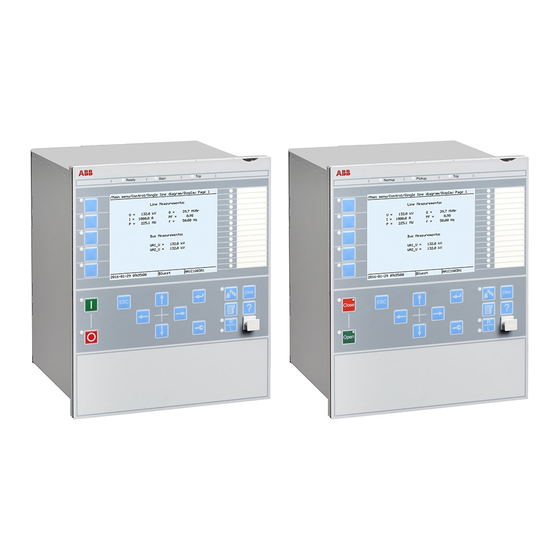
Section 8 1MRK 514 013-UEN - Technical data Section 8 Technical data Case and HMI display variants 8.1.1 Front side of the IED GUID-54166097-76E0-42A6-ADA7-D8580D1B2B1D V1 EN Figure 20: Front view of 6U half 19” IED The LHMI includes a monochrome LCD of 320x240 pixels. 650 series Installation Manual... -
Page 46: Rear Side Of The Ied
Section 8 1MRK 514 013-UEN - Technical data 8.1.2 Rear side of the IED GUID-A87FAB18-230C-4DBC-B13E-81DAE22DEA73 V1 EN Figure 21: Rear view of 6U half 19” Dimensions 650 series Installation Manual... -
Page 47: Enclosure Class
Section 8 1MRK 514 013-UEN - Technical data Table 4: Dimensions of the IED Description Type Value Width half 19" 220 mm Height half 19" 265.9 mm (6U) Depth half 19" 249.5 mm Weight half 19" box <10 kg (6U) half 19"... -
Page 49: Section 9 Accessories And Ordering Data
Section 9 1MRK 514 013-UEN - Accessories and ordering data Section 9 Accessories and ordering data Mounting kits 9.1.1 Flush mounting kit • Mounting frame • Screws • Nuts and washers • Dimensions for screw holes GUID-87C934B9-C35C-4424-9516-4BFB61146EE5 V1 EN Figure 22: Flush mounting frame 650 series Installation Manual... -
Page 50: Semi-Flush Mounting Kit
Section 9 1MRK 514 013-UEN - Accessories and ordering data Table 7: Mounting kit Items Order number Flush mounting kit for one 6U half 19” housing IED 1KHL400228R0001 9.1.2 Semi-flush mounting kit • Raising frame • Screws • Nuts and washers •... -
Page 51: Rack Mounting Kit For A Single Ied
Section 9 1MRK 514 013-UEN - Accessories and ordering data 9.1.3 Rack mounting kit for a single IED • Mounting brackets • Screws GUID-21666A58-8EF4-4C05-9D04-F91FBB224EA4 V1 EN Figure 24: 19” rack mounting panels Table 9: Mounting kit Items Order number 19" rack mounting kit for one 6U half 19” housing IED 1KHL400239R0001 9.1.4 Rack mounting kit for two IEDs... -
Page 52: Test Switch
Section 9 1MRK 514 013-UEN - Accessories and ordering data GUID-934DD622-5D8F-47D5-B8FB-354E7DF513A6 V1 EN Figure 25: 19” rack mounting parts for two IEDs Table 10: Mounting kit Items Order number 19" rack mounting kit for two 6U half 19” housing IEDs 1KHL400240R0001 9.1.5 Test switch... -
Page 53: Wall Mounting Kit For An Ied
Section 9 1MRK 514 013-UEN - Accessories and ordering data GUID-31472A64-A075-4D79-B2FF-C085B0D3B200 V1 EN Figure 26: 6U mounting bracket for test switch Table 11: Test switch mounting accessories Items Order number 19" rack mounting kit for one RTXP8 test switch (the test switch is not 1KHL400180R0001 included in the delivery) 19"... - Page 54 Section 9 1MRK 514 013-UEN - Accessories and ordering data GUID-11F37B1B-595B-4287-8FFB-E2A77EA2DA03 V1 EN Figure 27: 6U wall mounting brackets Table 12: Mounting kit Items Order number Wall-mounting kit (cabling towards the mounting wall) for one 6U half 19” 1KHL400200R0001 housing IED 650 series Installation Manual...
-
Page 55: Section 10 Glossary
Section 10 1MRK 514 013-UEN - Glossary Section 10 Glossary Alternating current Application configuration tool within PCM600 A/D converter Analog to digital converter ADBS Amplitude dead-band supervision ANSI American National Standards Institute Autoreclosing ASCT Auxiliary summation current transformer Adaptive signal detection American Wire Gauge standard External bi-stable relay British standard... - Page 56 Section 10 1MRK 514 013-UEN - Glossary Current transformer Capacitive voltage transformer Delayed auto-reclosing DARPA Defense Advanced Research Projects Agency (The US developer of the TCP/IP protocol etc.) DBDL Dead bus dead line DBLL Dead bus live line Direct current Discrete Fourier transform DIP-switch Small switch mounted on a printed circuit board...
- Page 57 Section 10 1MRK 514 013-UEN - Glossary General interrogation command Gas insulated switchgear GOOSE Generic object oriented substation event Global positioning system HDLC protocol High level data link control, protocol based on the HDLC standard HFBR connector Plastic fiber connector type Human machine interface HSAR...
- Page 58 Section 10 1MRK 514 013-UEN - Glossary provides packet routing, fragmentation and re-assembly through the data link layer. 2. Ingression protection according to IEC standard IP 20 Ingression protection, according to IEC standard, level 20 IP 40 Ingression protection, according to IEC standard, level 40 IP 54 Ingression protection, according to IEC standard, level 54 Internal fail signal...
- Page 59 Section 10 1MRK 514 013-UEN - Glossary Process bus Bus or LAN used at the process level, that is, in near proximity to the measured and/or controlled components Power supply module Parameter setting tool within PCM600 PT ratio Potential transformer or voltage transformer ratio PUTT Permissive underreach transfer trip RASC...
- Page 60 Section 10 1MRK 514 013-UEN - Glossary Trip circuit supervision Transmission control protocol. The most common transport layer protocol used on Ethernet and the Internet. TCP/IP Transmission control protocol over Internet Protocol. The de facto standard Ethernet protocols incorporated into 4.2BSD Unix.
- Page 61 Section 10 1MRK 514 013-UEN - Glossary Three times zero-sequence current. Often referred to as the residual or the earth-fault current Three times the zero sequence voltage. Often referred to as the residual voltage or the neutral point voltage 650 series Installation Manual...
- Page 64 Contact us ABB AB Substation Automation Products SE-721 59 Västerås, Sweden Phone +48 (0) 21 34 20 00 +48 (0) 21 14 69 18 www.abb.com/substationautomation...