Table of Contents
- 1 What's in the Box
- 2 Guided Setup
- 3 Connect Cables
- 4 Connect a Headset
- 5 Commonly Used Features
- 6 Placing Outgoing Calls
- 7 Ending a Call
- 8 Transferring Calls
- 9 Call Waiting
- 10 Volume Adjustment
- 11 Advanced Features
- 12 Call Pickup
- 13 Personal Contacts
- 14 Status Display Icons
- 15 Input Characters
- 16 Alphabetic Characters
Table of Contents

Related Manuals for NEC UNIVERGE BLUE ITK-6DGS-1


Summary of Contents for NEC UNIVERGE BLUE ITK-6DGS-1
- Page 1 Orchestrating a brighter world ™ UNIVERGE BLUE CONNECT START GUIDE ITK-6DGS-1 NDA-32023 Issue 2.0...
- Page 2 SOFTWARE LICENSE AGREEMENT NEC Platforms, Ltd. (hereinafter called “NECPF”) grants certain license to you pursuant to the terms and conditions of this Software License Agreement (hereinafter called the “Agreement”) to use the soft- ware (hereinafter called the “Software”) which is embedded in DT920S/DT930S series (hereinafter called the “Products”) and related documents (hereinafter called the “Documents”) (the Software and...
- Page 3 227.7202-4, NECPF provides the Licensed Products to U.S. Government End Users only pursuant to the terms and conditions therein. Contact Information North America NEC Corporation of America: 3929 W. John Carpenter Freeway, Irving, Texas 75063, U.S.A. TEL : +1-214-262-7525 Oceania NEC Australia Pty.
- Page 4 EMEA NEC Enterprise Solutions: Olympia 4, 1213 NT Hilversum, The Netherlands TEL : +31-35-6899111 Asia NEC Platforms, Ltd: 1753, Shimonumabe, Nakahara-ku, Kawasaki, Kanagawa 211-8666, Japan TEL : +81-44-435-5342...
- Page 5 WELCOME TO UNIVERGE BLUE CONNECT All of your business communications integrated, efficient and reliable.
-
Page 6: What's In The Box
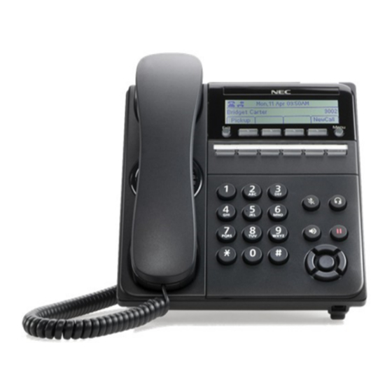
What’s in the box? NEC ITK-6DGS-1 ITK-6DGS-1 Base and Handset... -
Page 7: Guided Setup
Guided Setup Adjust the Angle of the Tilt Leg To adjust the tilt level of the ITK-6DGS-1: The height can be adjusted by moving the legs, which are attached to the bottom of the terminal. Turn the phone over (key side down). Adjust the legs to the desired height (upward to raise the height and downward to lower the height). - Page 8 Insert the RJ-9 handset connector into the “Handset” port on the back of the phone. 1 - Multiline Terminal 2 - Module Plug 3 - Curl Cord 4 - Groove 5 - Connector Configure a Headset To utilize a headset, you must first enable headset mode on the ITK-6DGS-1: Press the “Menu”...
-
Page 9: Connect A Headset
Connect a Headset To connect a headset: Insert the RJ-9 headset connector into the “HEADSET” port on the back of the phone. 1 - Multiline Terminal 2 - Module Plug 3 - Curl Cord 4 - Groove 5 - Headset Connector The phone picks the headset as the default communication method that is used when placing and answering phone calls. - Page 10 Features NEC ITK-6DGS-1 Reference Feature Feature Description Number If missed call notification for the call indicator lamp is disabled (default), the lamp flashes for incoming and missed calls, and displays steady red for message waiting. If missed call notification for the call indicator ...
- Page 11 Reference Feature Feature Description Number This key allows you to exit from the Menu or Help Exit key mode and go back to the telephone main screen. The soft keys show the available features for your current activity. Any feature shown at the bottom of Soft keys the LCD is available.
- Page 12 Voicemail Box Setup RECORDING YOUR PERSONAL VOICEMAIL GREETING Press the “Voicemail” soft key. Enter the PIN provided to you by your Administrator, followed by the # key. Select option 3 for personal options. Select option 1 to record your voicemail greeting. Follow the voice prompts to record and check your greeting.
-
Page 13: Commonly Used Features
Commonly Used Features PLACING OUTGOING CALLS When the phone is not in use: Pick up the handset or press the “Speakerphone” button. Dial an extension or telephone number. When you are already on a call: Press the “More" >>> soft key. Press the “New Call”... -
Page 14: Ending A Call
ENDING A CALL On a Handset: Hang up or press the “End Call” soft key. On a Headset: Press the “Headset” button. On Speakerphone: Press the “Speaker” button HOLD Placing a Call On Hold: While on a call, press the “Hold” button. -
Page 15: Call Waiting
Wait for the party to answer. Announce the call and indicate you are transferring a call to them. Press the “Transfer” soft key to transfer the call. CALL WAITING While already on a call, and a new call rings in, you will hear a beep tone emitted by your phone. -
Page 16: Advanced Features
VOICEMAIL While the phone is not in use, press the “Voicemail” soft key. Enter your voicemail PIN followed by #. Press 1 to listen to new voicemail messages. Advanced Features CALL PARK To Place a Call on Park: While on a call press the Call Park line key (programmed previously ... - Page 17 To Pickup a Call from any Group (Group Call Pickup): From any phone, dial *97 and the Group number that the call is ringing, or select the Call Pickup “from specific Pickup Group” (programmed previously via Control Panel). To Pickup a Call from any Station (Any Call Pickup): From any phone, dial *96 to answer a call of any ringing station or ...
- Page 18 INTERCOM To Intercom a Station (Voice Announce): Dial *90 and the extension number of the user you want to intercom. CALLFLIP To Transfer a Call to Your Other Devices: While on a call, select the "Transfer" soft key, "Blind" soft key and Dial ...
-
Page 19: Personal Contacts
PAGING To Page Phones in a Group: Dial the Page Group extension number or select the Paging line key (programmed previously via Control Panel). To Answer a Page: You can dial *80, to be connected to the person that initiated the Page ... - Page 20 To add a Personal Directory entry: Press the Menu key. Select 1 Personal Contacts. Press the “>>>” soft key and then the “Add” soft key. Use the keypad to enter a name for the Personal Contact, then press the middle button on the cursor pad or the “OK” soft key. Use the * key to switch between uppercase and lowercase keypad entry mode.
-
Page 21: Status Display Icons
Icon Display Status Display Icons The LCD on the phone displays icons that provide notification for events, such as missed calls and voice mail. The icons appear in the topmost display line, known as the title bar. Feature Images Description Indicates the phone is currently registered with a Registered SIP server. - Page 22 Feature Images Description Transfer/Conference Transfer the primary call to a secondary call. Call Indicates that the number you have dialed for the Transfer or Conference is ringing. Transfer/Conference Ringing This icon only displays for calls that are monitored by the system, such as internal calls. Transfer/Conference Focus is on the primary call.
- Page 23 Monitor Presence Icons Type Status Images Registered Line Key Unregistered Speed Dial Key Not Available (No Monitoring) Idle Ringing Subscription Failed Online (3C system only) On the Phone Held Busy...
- Page 24 Menu List Default Menu Item Description Value Select this option to set up for ring tone. Ringtone (Refer to Ringtone on page 20.) Select this option to set up for headset. Headset (Refer to Headset on page 20.) English Language Select this option to set up for the language.
- Page 25 Ringtone Default Menu Item Description Value Internal Ringtone Select this option to specify the internal ringtone. Default External Ringtone Select this option to specify the external ringtone. Default Headset Default Menu Item Description Value Enable/Disable Select this option to specify whether to use the headset. Disable Ringing Select this option to specify which device rings.
-
Page 26: Input Characters
Input Characters The following tables show the character sets (uppercase, lowercase) and numeric that are available on your phone. ALPHABETIC CHARACTERS When entering the name, you can enter uppercase and lowercase standard and European characters. The keypad is in upper case entry mode upon entering the screen. - Page 27 Uppercase Alphabetical Character Set...
- Page 28 Lowercase Alphabetic Character Set...
- Page 29 Numeric Character Set When in numeric character entry mode, you can use the numbered keys on the phone to enter numbers, and the # key to enter special characters. You can switch between character sets by pressing the key. The full numeric character set is only available when you are in a field that also allows alphabetic input.
- Page 30 Guided Option Setup Wall Mount the Phone You can wall mount a multiline terminal using the base cover or an optional wall mount unit. When optional adapters are used, the multiline terminal must be installed on the wall using the WM-L UNIT. Wall Mounting a DT900 Multiline Terminal using the Base Plate Please note, because of the variation in wall plates, this method is not recommended.
- Page 31 To Wall Mount the Multiline Terminal Plug line cord in the wall receptacle. Leave about eight inches of cord and bundle the remaining cord as shown in the following diagram. Bundling the Line Cord Ensure the Tilt Legs are in the flat (unused) position. Plug the line cord or LAN cable into the multiline terminal.
- Page 32 To Wall Mount the Base on the Wall Plate Locate the screw holes on the base and hang the cover over the screws on the wall plate. Wall Mount on Wall Plate Hang the terminal on the base. When it is correctly mounted, it will be flush with the wall. Wall Mounted Unit...
- Page 33 To Remove the Terminal from the Wall Mounted Base Plate Push up on the terminal until it comes loose. Removing Wall Mounted Unit Directory Card Unit A directory card can be attached to ITK-6DGS. The directory card can be used to record frequently dialed numbers or other important information.
- Page 34 CG Directory Unit (L) 1 - Cover 2 - Directory Card 3 - Holder 4 - Holder Joint Hole...
- Page 35 WM-L Unit The WM-L UNIT (Wall Mount Unit) is used to attach any DT Series multiline terminal to the wall. This unit connects to the bottom of the telephone. When optional adapters are used, the multiline terminal must be installed on the wall using the WM-L UNIT.
- Page 36 To Install the WM-L Unit Attach the WM-L UNIT to the wall using six screws or using two wall mounted screws as shown in the following diagram. Attach WM-L UNIT Using Screws 1 - WM-L UNIT 2 - Screws 3 - Screws 4 - WM-L Unit Plug one end of the line cord into the wall receptacle.
- Page 37 To Align Cutouts for WM-L Unit Align the four cutouts on the bottom of the multiline terminal with the tabs on the WM-L UNIT as shown in the following diagrams. Align Cutouts Align Tabs...
- Page 38 Push down until the multiline terminal snaps into place. WM-L UNIT Installed To release the multiline terminal from the WM-L UNIT, press the release button and push the telephone up. WM-L UNIT Release Button...
- Page 39 Mount Multiline Terminal On Wall Plate Using WM-L UNIT Locate the screw holes on the base and hang the cover over the screws on the wall plate. Attach WM-L UNIT to Wall Plate Because of variation in wall plates, this method is not recommended. NOTE Plug one end of the line cord into the wall receptacle.
- Page 40 Align Cutouts Align Tabs...
- Page 41 Push down until the multiline terminal snaps into place. Attach WM-L UNIT Installed To remove the WM-L UNIT from the wall panel, push up on the telephone until it comes loose. Attach WM-L UNIT Removed...
- Page 42 To separate the multiline terminal from the WM-L UNIT, press the release button and slide the multiline terminal up. Attach WM-L UNIT Release Button...
- Page 43 We are here to help. http://kb.univerge.blue/main/ ©NEC Corporation 1994-2020...