Mitsubishi Electric FRESH MASTER GUF-50RDH3 Handbook
Hide thumbs
Also See for FRESH MASTER GUF-50RDH3:
- Installation instructions manual (22 pages) ,
- Operating instructions manual (15 pages)

Related Manuals for Mitsubishi Electric FRESH MASTER GUF-50RDH3


Summary of Contents for Mitsubishi Electric FRESH MASTER GUF-50RDH3
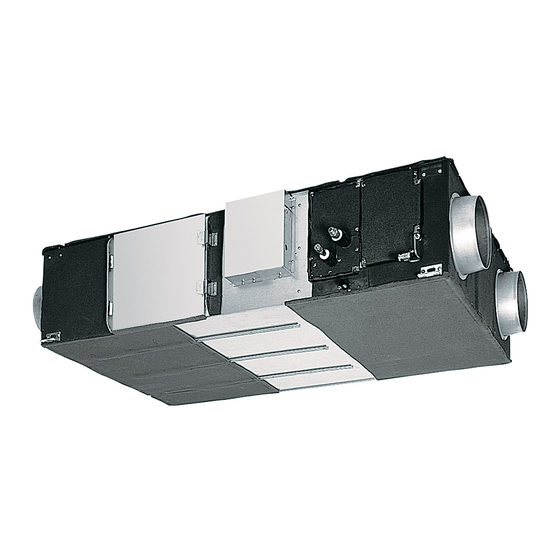
- Page 1 Issued July 2004 No. U-101 FRESH MASTER HAND BOOK (For HONG KONG) FOR DEALERS Model: GUF-50RDH GUF-100RDH Model name The picture is shown GUF-50RDH3. Notice: The term of validity is for a year from the issued date. MITSUBISHI ELECTRIC CORPORATION...
-
Page 2: Table Of Contents
Contents Safety precautions..............3-4 1. Specifications ................4 2. Dimensions................5 3. Wiring diagrams ..............6 4. Maintenance procedures............ 7-14 4-1 Blower Parts..............7-8 4-2 Damper Motor Part (All units available)........ 9 4-3 Circuit Board Part............9-10 4-4 Humidifier Parts............. 10-11 4-5 Heat exchanger for refrigerant Part....... -
Page 3: Safety Precautions
Safety precautions Please be sure to read the following safety precautions thoroughly before commencing with the maintenance work, and conduct the inspection and repair of the product in a safe manner. The types and levels of danger that may arise if the product is handled incorrectly are described by using the warning symbols shown below. -
Page 4: Specifications
Incorrect handling of the product may result in serious injury Caution or damage to properties including buildings and equipment. ♦ ♦ ♦ ♦ Caution for bodily injury Prevent water leakage •Do not conduct any work at a location •Before removing any of the water-related parts, com- where you do not have a sure footing. -
Page 5: Dimensions
2. Dimensions GUF-50RDH3,GUF-100RDH3 Location at which the duct direction can be changed Damper plate Ceiling suspension fixture (4 places×13×30 length hole for GUF-50RDH3) Ceiling suspension fixture (4 places×15×30 length hole for GUF-100RDH3) Air exhaust fan (Exhaust air) (Return air) Air supply fan (Supply air) (Outdoor air) Solenoid valve unit with... -
Page 6: Wiring Diagrams
3. Wiring diagrams GUF-50RDH3,GUF-100RDH3 — 6 —... -
Page 7: Maintenance Procedures
4. Maintenance procedures 4-1 Blower Parts 1Remove the cover fixing special screw. Maintenance cover 2Pull back the hinged clip. 2Open the door and lift off of the hinge brackets. Special screw Hinge 3Remove Filters from the unit. 4Remove Lossnay cores from the unit. Lossnay core Filter 5Remove screw from the core-guide,Remove core-... - Page 8 6Remove separator from the blower portion. 7Remove connections motor lead wire. Separator 8Remove screws from the motor base. Motor Base Motor 9Remove the pre-assembled blower. Pre-assembled Blower — 8 —...
-
Page 9: Damper Motor Part (All Units Available)
4-2 Damper Motor Part (All units available) 1Remove (2) screws out from the damper motor cover. Damper Motor Cover 2Take the damper motor out of the cover. Damper Motor 4-3 Circuit Board Part 1Remove the 4 screws from the control cover. Screw Control Cover 2Remove the 3 screws from capacitors. -
Page 10: Humidifier Parts
3Remove all harnesses connected to the circuit board. 4Take the circuit board out. Circuit Board 4-4 Humidifier Parts The photograph shows GUF-100RDH3. 1Remove the 7 screws to remove the humidifier cover. Screw Humidifier cover 2Remove the Humidifier cover (Inner lid). Humidifier cover (Inner lid) —... - Page 11 3Remove the water supply tube from the humidifying ele- Water supply tube ment. 4Holding the hose bands indicated by [1] to [6] with your fingers, remove the water supply tubes. Referring to the Water supply tube procedure entitled “removing the humidifying elements” below, remove the water supply tube at the rear while taking out the front humidifying element.
-
Page 12: Heat Exchanger For Refrigerant Part
4-5 Heat exchanger for refrigerant Part 1Remove the 11 screws to remove cover (L) and cover (S). Cover (L) Screw Cover (S) (9 screws for the GUF-50RDH3) 2Remove connections of themistor lead wire and lenear Screw Fixture Heat exchanger expansion valve lead wire. 3Remove the 2 screws to remove the Fixture. -
Page 13: Solenoid Valve And Water Sencor Part
Water sensor and solenoid valve installation positions 4-6 Solenoid valve and water sencor Part 1Remove connections of solenoid valve lead wire Connection Solenoid Valve and water sencor lead wire. Connection for water sencor 2Remove pipes connected to the solenoid valve. cover (solenoid valve) 3Remove the 2 screws to remove the cover (solenoid valve). - Page 14 5Remove a screw to remove the water sencor. Installed condition of GUF-100RDH3 Water sensor plate Fixing position of water sensor plate Fixing position of (GUF-50RDH3) water sensor plate (GUF-100RDH3) 6The hole at the fixing position of the water sensor plate Installed condition of GUF-50RDH3 (GUF-50RDH3) is no longer visible.
-
Page 15: Parts List
5. Parts list Please note the following when using the parts list. 1. When ordering parts, always indicate the part number, part name, and number of parts required. 2. Parts are not always available, and it may take time for you to receive them. 3. -
Page 16: Guf-50Rdh3
Model GUF‑50RDH3 Parts No. Name of part Q'ty Critical Remarks Price pcs/unit for safety Y50 062 718 Filter H00 000 488 PTT screw 4×12 R50 216 381 Core guide R50 216 710 Lossnay core R50 263 381 Core guide R50 474 737 Linear expansion valve H00 000 487 PTT screw 4×8 R50 028 610 Flange R50 351 708 Cover R50 466 344 Hinge Y50 029 712 Fix plate R50 095 380 Hanger H00 000 244 PT screw 6×12 M34 074 017 Special screw 4×11 R50 429 691 Cover(L) Y55 007 366 Model name X50 002 707 Maintenance cover R50 429 697 Cover(S) H00 189 007 PTT screw 5×10... - Page 17 14 15 16 17 18 19 20 21 22 23 24 25 26 27 28 29 30 31 32 33 34 35 36 37 38 39 — 17 —...
- Page 18 Model GUF‑50RDH3 Parts No. Name of part Q'ty Critical Remarks Price pcs/unit for safety R50 331 067 Special nut M34 398 077 Tab washer R50 351 480 Centrifugal fan φ220 R50 478 707 Motor base M34 706 465 Special washer Y50 062 452 Motor R50 351 713 Motor fix plate H00 189 007 PTT screw 5×10 Y55 003 451 Motor 11 ...
- Page 19 Air Supply fan assembly Air Exhaust fan assembly — 19 —...
- Page 20 Model GUF‑50RDH3 Parts No. Name of part Q'ty Critical Remarks Price pcs/unit for safety R50 472 716 Damper support R50 069 156 Pull spring R50 054 225 Bush R50 232 150 Rod Y50 061 693 Damper motor cover Y50 061 260 Damper motor 220×240V H00 312 007 PTT screw 4×6 Y55 003 216 Thermistor D41 093 224 Cord clamper R50 399 224 Cord clip H00 000 349 PT screw 4×8 Y55 001 217 Transformer H00 013 076 Lock washer H00 011 008 PT screw 4×8(BS) For earth Y55 007 367 Wiring diagram R50 429 693 Cover R50 430 693 Side plate R50 351 225 Bush...
- Page 21 For air exhaust (EA) For air supply (SA) — 21 — — 21 —...
-
Page 22: Guf-100Rdh3
Model GUF‑100RDH3 Parts No. Name of part Q'ty Critical Remarks Price pcs/unit for safety Y50 063 718 Filter H00 000 488 PTT screw 4×12 R50 219 381 Core guide R50 219 710 Lossnay core R50 266 381 Core guide R50 474 737 Linear expansion valve H00 000 487 PTT screw 4×8 R50 430 609 Flange R50 358 704 Cover R50 466 344 Hinge Y50 029 712 Fix plate R50 054 383 Hanger H00 000 244 PT screw 6×12 M34 074 017 Special screw 4×11 R50 430 691 Cover(L) X50 004 707 Maintenance cover Y55 008 366 Model name H00 189 007 PTT screw 5×10 R50 430 692 Cover(S) - Page 23 14 15 16 17 18 19 20 21 22 23 24 25 26 27 28 29 30 31 32 33 34 35 36 37 38 39 40 — 23 —...
- Page 24 Model GUF‑100RDH3 Parts No. Name of part Q'ty Critical Remarks Price pcs/unit for safety R50 218 067 Special nut(12) K83 466 113 Special washer(12) R50 479 480 Centrifugal fan φ245 R50 480 707 Fan base H00 189 007 PTT screw 5×0 R50 264 711 Inlet plate H00 157 008 PT screw 6×20 M34 043 080 Special washer R50 000 095 Spacer R50 217 225 Bush R50 218 712 Motor fix leg Y50 033 104 Key 5×5×11.5 Y50 063 452 Motor H00 061 050 Nut(6) K83 195 080 Special washer Y55 004 451 Motor ...
- Page 25 Air Supply fan assembly Air Exhaust fan assembly 58 57 — 25 —...
- Page 26 Model GUF‑100RDH3 Parts No. Name of part Q'ty Critical Remarks Price pcs/unit for safety R50 473 715 Damper support R50 074 156 Pull spring R50 054 225 Bush R50 265 150 Rod Y50 061 693 Damper motor cover Y50 061 260 Damper motor 220×240V H00 312 007 PTT screw 4×6 Y55 004 215 Thermistor D41 093 224 Cord clamper R50 399 224 Cord clip H00 000 349 PT screw 4×8 Y55 001 217 Transformer H00 013 076 Lock washer H00 011 008 PT screw 4×8(BS) For earth Y55 007 367 Wiring diagram R50 429 693 Cover R50 430 693 Side plate R50 351 225 Bush...
- Page 27 For air exhaust (EA) For air supply (SA) — 27 — — 27 —...
-
Page 28
Printed in Japan in July, 2004 35
...