Table of Contents
Quick Links
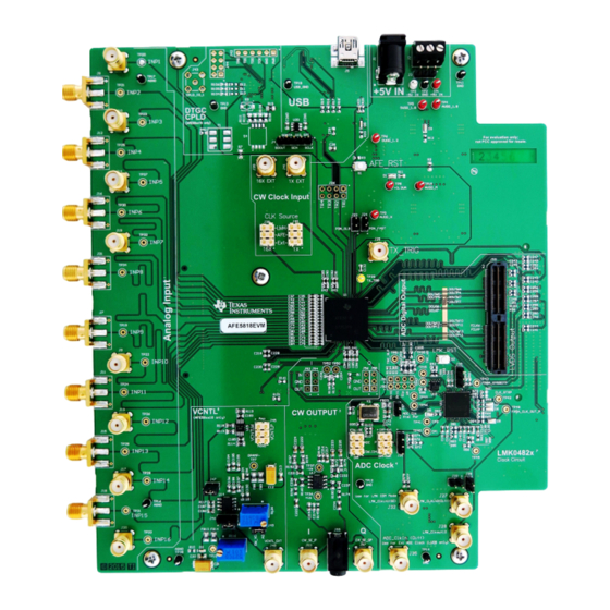
AFE5818 16-Channel Analog Front End Evaluation Module
This user's guide gives a general overview of the AFE5818 evaluation module (EVM) and provides a
general description of the features and functions to be considered while using this module. This manual is
applicable to the AFE5818 analog front-end, and to the Rev. C version of the EVM hardware. The
AFE5818 EVM provides a platform for evaluating the AFE under various signal, clock, reference, and ADC
output formats. In addition, the EVM supports the testing of both the LVDS interface as well as the
JESD204B interface. Note that the TSW1400EVM capture card is required for LVDS, and TSW14J56EVM
is required for JESD204B.
This user's guide refers to software HMC-DAQ GUI v.2.8 or higher, and HSDCPro Software v.4.1 or
higher.
For any further questions regarding the EVM, GUI or device, please contact:
•
1
2
2.1
3
4
4.1
4.2
4.3
Appendix A
Software Installation
Appendix B
Hardware Reference
1
AFE5818 EVM Circuits Map
2
LVDS Evaluation Setup Overview
3
TSW1400EVM and AFE5818 Hardware Setup for LVDS Capture
4
Clock Configuration on AFE EVM for LVDS
5
AFE_RST Hardware Reset Button
6
Initialize Device
7
GUI Quick Start Setup: Configure for Ramp Format
8
LMK04826 Clock Testpoints
9
HSDC Pro Set-up
10
AFE5818 RAMP Capture
11
JESD Lane Rate Information
12
13
14
15
16
17
....................................................................................
...................................................................................................
..............................................................................................
..............................................................................................
..............................................................................................
................................................................................................
.........................................................................................
........................................................................................
..............................................................................................................
...............................................................................................
............................................................................................................
.................................................................................................
.............................................................................................
................................................................................................
...................................................................................
..........................................................................................................
..............................................................................................................
................................................................................
AFE5818 16-Channel Analog Front End Evaluation Module (EVM Rev. C)
Copyright © 2015, Texas Instruments Incorporated
Contents
.............................................
.........................................................
List of Figures
...................................................
.............................................................................
....................................................................
.......................................................................
User's Guide
SLOU430 - October 2015
(EVM Rev. C)
..........................................
..........................................
.......................................
3
3
3
5
5
5
6
11
15
27
3
4
5
6
6
7
7
8
9
10
10
11
11
12
12
13
14
1
Table of Contents

Related Manuals for Texas Instruments AFE5818


Summary of Contents for Texas Instruments AFE5818
-
Page 1: Table Of Contents
This manual is applicable to the AFE5818 analog front-end, and to the Rev. C version of the EVM hardware. The AFE5818 EVM provides a platform for evaluating the AFE under various signal, clock, reference, and ADC output formats. - Page 2 HMC-DAQ GUI Install: Progress ..................HMC-DAQ GUI Install: Finished List of Tables ..................AFE5818 EVM Bill of Materials AFE5818 16-Channel Analog Front End Evaluation Module (EVM Rev. C) SLOU430 – October 2015 Submit Documentation Feedback Copyright © 2015, Texas Instruments Incorporated...
-
Page 3: Evm Hardware And Circuits Overview
The AFE5818 EVM can be tested using the TSW1400EVM for LVDS data interface, or using the TSW14J56EVM for the JESD204B data interface. LVDS Interface ( AFE5818 EVM and TSW1400EVM) As shown in , mating the AFE5818 EVM with a TSW1400 EVM allows for testing using the LVDS data interface. SLOU430 – October 2015 AFE5818 16-Channel Analog Front End Evaluation Module (EVM Rev. - Page 4 Vcntl circuit. Alternatively, a dual ±5-V supply can power the EVM through a connector located at P1. All supplies for the AFE5818 device is derived from this +5-V supply. This +5-V power supply must be able to source up to 2 A, and –5 V supply must provide up to 1 A. The –5 V supply is used for the negative supply of amplifiers in the CW output external circuitry and V circuit.
-
Page 5: Gui Software Installation
Figure 3. TSW1400EVM and AFE5818 Hardware Setup for LVDS Capture 1. For LVDS data, mate the TSW1400 EVM at connector J3 to the AFE5818 EVM at connector P900 through the high-speed ADC interface connector. For JESD data, mate the TSW14J56 EVM at connector J4 to the AFE5818 EVM at connector P800 through the FPGA Mezzanine Card (FMC) connector. -
Page 6: Capturing A Ramp Test Pattern With The Lvds Or Jesd Interface
P1. 3. Connect the USB cable from PC to J50 (USB) located on the top side of the AFE5818 EVM. Connect the USB cable from PC to J5 (USB_IF) of the TSW1400 EVM or J9 of the TSW14J56 EVM . Note: TI recommends that the PC USB port be able to support USB2.0. - Page 7 Testing the AFE5818 EVM Data Capture with LVDS and JESD Interface www.ti.com Figure 6. Initialize Device 4. Choose the desired serialized data format. LVDS data capture requires the TSW1400, and JESD data capture requires the TSW14J56. 5. Choose Ramp Test Pattern for the ADC format.
- Page 8 Testing the AFE5818 EVM Data Capture with LVDS and JESD Interface www.ti.com Figure 8. LMK04826 Clock Testpoints Return to the HSDC Pro GUI and perform the following steps highlighted in Figure 1. Press the ADC tab in HSDCpro. 2. Change the plot type from Real FFT to Codes.
- Page 9 Testing the AFE5818 EVM Data Capture with LVDS and JESD Interface www.ti.com Figure 9. HSDC Pro Set-up 5. A RAMP capture should appear, as shown in Figure SLOU430 – October 2015 AFE5818 16-Channel Analog Front End Evaluation Module (EVM Rev. C) Submit Documentation Feedback Copyright ©...
- Page 10 Testing the AFE5818 EVM Data Capture with LVDS and JESD Interface www.ti.com Figure 10. AFE5818 RAMP Capture JESD Only: The following message or similar message appears after hitting capture for the first time after a new firmware has been loaded and, subsequently, any time the JESD line rate changes (for example, when the ADC output data rate is changed.) Press OK.
-
Page 11: Capturing An Analog Input Signal With The Lvds Or Jesd Interface
Figure 13. HSDC Pro Error Refers to No Clocks from AFE Capturing an Analog Input Signal with the LVDS or JESD Interface This section describes the Software setup for capturing a sinusoidal input using the AFE5818 . This section assumes that the user has completed the steps from Section 4.2. -
Page 12: Change Adc Format To Analog Input
Testing the AFE5818 EVM Data Capture with LVDS and JESD Interface www.ti.com Figure 14. Change ADC Format to Analog Input 2. Select firmware: AFE5818 _14X_B(LVDS) or AFE5818 B_4L_16x(JESD). 3. Change the plot type from Codes to Real FFT. 4. Enter 50M in the field labeled ADC Output Data Rate. -
Page 13: Capture Button
Testing the AFE5818 EVM Data Capture with LVDS and JESD Interface www.ti.com Figure 16. Capture Button A capture similar to that shown in Figure 17 should appear. SLOU430 – October 2015 AFE5818 16-Channel Analog Front End Evaluation Module (EVM Rev. C) Submit Documentation Feedback Copyright ©... -
Page 14: Afe5818 Analog Input Capture For Snr
Testing the AFE5818 EVM Data Capture with LVDS and JESD Interface www.ti.com Figure 17. AFE5818 Analog Input Capture for SNR AFE5818 16-Channel Analog Front End Evaluation Module (EVM Rev. C) SLOU430 – October 2015 Submit Documentation Feedback Copyright © 2015, Texas Instruments Incorporated... - Page 15 Figure 18. HSDC Pro Install (Begin) 3. Leave the destination directories as the default location for the TSW1400 GUI installation, and press the Next button as shown in Figure SLOU430 – October 2015 Software Installation Submit Documentation Feedback Copyright © 2015, Texas Instruments Incorporated...
- Page 16 High Speed Data Converter Pro (HSDC Pro) GUI Installation www.ti.com Figure 19. HSDC Pro Install (Install Directory) 4. Read the License Agreement from Texas Instruments and select I accept the License Agreement, then press the Next button as shown in Figure Software Installation SLOU430 –...
- Page 17 5. Read the License Agreement from National Instruments and I accept the License Agreement, then press the Next button as in Figure Figure 21. HSDC Pro Install (NI License Agreement) 6. Press the Next button as in Figure 20 SLOU430 – October 2015 Software Installation Submit Documentation Feedback Copyright © 2015, Texas Instruments Incorporated...
- Page 18 Figure 23. HSDC Pro Install (Installation Progress) 8. When finished, the window shown in Figure 22 appears, indicating Installation Complete. Press the Next button. Software Installation SLOU430 – October 2015 Submit Documentation Feedback Copyright © 2015, Texas Instruments Incorporated...
- Page 19 24, a computer restart may be requested, depending on whether the PC already has the National Instruments MCR installer. If requested, press the Restart button to complete the installation. SLOU430 – October 2015 Software Installation Submit Documentation Feedback Copyright © 2015, Texas Instruments Incorporated...
- Page 20 1. Press the Run button to begin the download and installation. A prompt will appear for the desktop shortcut. Figure Figure 27. HMC-DAQ GUI Install: Driver Installation 2. Press the Next button as shown in Figure Software Installation SLOU430 – October 2015 Submit Documentation Feedback Copyright © 2015, Texas Instruments Incorporated...
- Page 21 HMC-DAQ GUI Installation www.ti.com Figure 28. HMC-DAQ GUI Install: Destination Directory 3. Set the destination directories for the AFE5818 EVM GUI installation, or leave as default and press the Next button as shown in Figure SLOU430 – October 2015 Software Installation Submit Documentation Feedback Copyright ©...
- Page 22 HMC-DAQ GUI Installation www.ti.com Figure 29. HMC-DAQ GUI Install: Set Directory 4. Read the License Agreement from Texas Instruments and select the I accept the License Agreement button, then press the Next button as shown in Figure Software Installation SLOU430 – October 2015 Submit Documentation Feedback Copyright ©...
- Page 23 HMC-DAQ GUI Installation www.ti.com Figure 30. HMC-DAQ GUI Install: TI License Agreement 5. To begin the installation, press the Next button as shown in Figure SLOU430 – October 2015 Software Installation Submit Documentation Feedback Copyright © 2015, Texas Instruments Incorporated...
- Page 24 HMC-DAQ GUI Installation www.ti.com Figure 31. HMC-DAQ GUI Install: Confirmation 6. The window shown in Figure 32 should appear showing that the installation is in progress. Software Installation SLOU430 – October 2015 Submit Documentation Feedback Copyright © 2015, Texas Instruments Incorporated...
- Page 25 Figure 32. HMC-DAQ GUI Install: Progress 7. Upon completion of the installation, the window in Figure 33 appears. Press the Finish button to continue. SLOU430 – October 2015 Software Installation Submit Documentation Feedback Copyright © 2015, Texas Instruments Incorporated...
- Page 26 HMC-DAQ GUI Installation www.ti.com Figure 33. HMC-DAQ GUI Install: Finished Software Installation SLOU430 – October 2015 Submit Documentation Feedback Copyright © 2015, Texas Instruments Incorporated...
- Page 27 Appendix B SLOU430 – October 2015 Hardware Reference AFE5818 EVM Bill of Materials Table 1 lists the AFE5818 EVM bill of materials (BOM). Table 1. AFE5818 EVM Bill of Materials Designator Value Description Package Reference Part Number Alternate Part Alternate MFR...
-
Page 28: Slou430 - October 2015
Appendix B www.ti.com Table 1. AFE5818 EVM Bill of Materials (continued) Designator Value Description Package Reference Part Number Alternate Part Alternate MFR Number C100, C173 10uF CAP, CERM, 10 µF, 6.3 V, 0603 C0603C106M9PACTU Kemet +/- 20%, X5R, 0603 C101, C103, C114, CAP, CERM, 1 µF, 6.3 V, +/-... - Page 29 Appendix B www.ti.com Table 1. AFE5818 EVM Bill of Materials (continued) Designator Value Description Package Reference Part Number Alternate Part Alternate MFR Number J6, J9, J10, J13, J14, SMA Straight PCB Socket SMA Straight PCB 5-1814832-1 J17, J19, J20, J25,...
- Page 30 Appendix B www.ti.com Table 1. AFE5818 EVM Bill of Materials (continued) Designator Value Description Package Reference Part Number Alternate Part Alternate MFR Number R121, R125 1.00M RES, 1.00 M, 1%, 0.1 W, 0603 CRCW06031M00FKEA Vishay-Dale 0603 R122 RES, 200 ohm, 0.1%,...
- Page 31 Appendix B www.ti.com Table 1. AFE5818 EVM Bill of Materials (continued) Designator Value Description Package Reference Part Number Alternate Part Alternate MFR Number 1.1 nV/rtHz Noise, Low D0008A OPA211AIDR Texas Equivalent None Power, Precision Operational Instruments Amplifier, 4.5 to 36 V, -40 to 125 degC, 8-pin SOIC (D0008A), Green (RoHS &...
- Page 32 Appendix B www.ti.com Table 1. AFE5818 EVM Bill of Materials (continued) Designator Value Description Package Reference Part Number Alternate Part Alternate MFR Number R83, R104, R105, RES, 100, 1%, 0.1 W, 0402 0402 ERJ-2RKF1000X Panasonic R106 R96, R140 RES, 0, 5%, 0.063 W, 0402...
- Page 33 STANDARD TERMS AND CONDITIONS FOR EVALUATION MODULES Delivery: TI delivers TI evaluation boards, kits, or modules, including any accompanying demonstration software, components, or documentation (collectively, an “EVM” or “EVMs”) to the User (“User”) in accordance with the terms and conditions set forth herein. Acceptance of the EVM is expressly subject to the following terms and conditions.
- Page 34 FCC Interference Statement for Class B EVM devices NOTE: This equipment has been tested and found to comply with the limits for a Class B digital device, pursuant to part 15 of the FCC Rules. These limits are designed to provide reasonable protection against harmful interference in a residential installation.
- Page 35 【無線電波を送信する製品の開発キットをお使いになる際の注意事項】 開発キットの中には技術基準適合証明を受けて いないものがあります。 技術適合証明を受けていないもののご使用に際しては、電波法遵守のため、以下のいずれかの 措置を取っていただく必要がありますのでご注意ください。 1. 電波法施行規則第6条第1項第1号に基づく平成18年3月28日総務省告示第173号で定められた電波暗室等の試験設備でご使用 いただく。 2. 実験局の免許を取得後ご使用いただく。 3. 技術基準適合証明を取得後ご使用いただく。 なお、本製品は、上記の「ご使用にあたっての注意」を譲渡先、移転先に通知しない限り、譲渡、移転できないものとします。 上記を遵守頂けない場合は、電波法の罰則が適用される可能性があることをご留意ください。 日本テキサス・イ ンスツルメンツ株式会社 東京都新宿区西新宿6丁目24番1号 西新宿三井ビル 3.3.3 Notice for EVMs for Power Line Communication: Please see http://www.tij.co.jp/lsds/ti_ja/general/eStore/notice_02.page 電力線搬送波通信についての開発キットをお使いになる際の注意事項については、次のところをご覧くださ い。http://www.tij.co.jp/lsds/ti_ja/general/eStore/notice_02.page SPACER EVM Use Restrictions and Warnings: 4.1 EVMS ARE NOT FOR USE IN FUNCTIONAL SAFETY AND/OR SAFETY CRITICAL EVALUATIONS, INCLUDING BUT NOT LIMITED TO EVALUATIONS OF LIFE SUPPORT APPLICATIONS.
- Page 36 Notwithstanding the foregoing, any judgment may be enforced in any United States or foreign court, and TI may seek injunctive relief in any United States or foreign court. Mailing Address: Texas Instruments, Post Office Box 655303, Dallas, Texas 75265 Copyright © 2015, Texas Instruments Incorporated...
- Page 37 IMPORTANT NOTICE Texas Instruments Incorporated and its subsidiaries (TI) reserve the right to make corrections, enhancements, improvements and other changes to its semiconductor products and services per JESD46, latest issue, and to discontinue any product or service per JESD48, latest issue.
- Page 38 Mouser Electronics Authorized Distributor Click to View Pricing, Inventory, Delivery & Lifecycle Information: Texas Instruments AFE5818EVM...