Table of Contents
Quick Links
APPLICATION
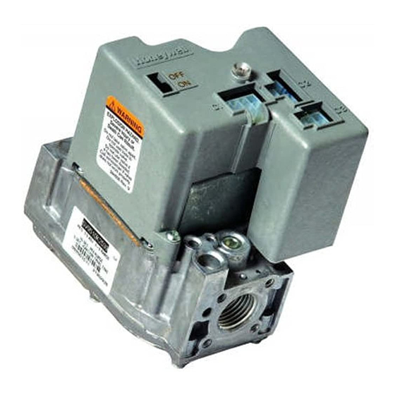
The SV9540; SV9640 SmartValve™ System Controls
combine gas flow control and electronic intermittent pilot
sequencing functions into a single unit. The low voltage
igniter, flame sensor and pilot burner are supplied by the
Q3450 or Q3480 Pilot Hardware. Provides all gas ignition
safety functions by controlling gas flow, ignition source,
and a 120 Vac or 240 Vac combustion air blower. The
control also monitors the appliance airflow proving switch
and limit string to assure proper appliance operation.
Provides prepurge, postpurge, timed trial for pilot igniton,
with 100 percent shutoff and continuous retry. Diagnostic
LED indicates system status.
This control communicates directly with the ST9160
Electronic Fan Timer (EFT) in typical forced warm air
furnace applications. It also interfaces with the 208907
Terminal Board, providing compatibility with power stealing
thermostats. Or, it directly interfaces with the appropriate
power supplies and a system thermostat for additional
appliance applications. When controlled directly by a
thermostat, the control does not provide a postpurge
function, as power to the control is removed when the
thermostat call for heat ends.
The SV9540; SV9640 system is suitable for a wide range
of fan assisted combustion gas-fired appliances including
furnaces, rooftop furnaces, boilers, unit heaters, infrared
heaters, water heaters and commercial cooking appli-
ances. The specific application of the SmartValve System
is the responsibility of the appliance manufacturer. See
Table 1 for temperature ranges and regulator types.
SPECIFICATIONS
CAUTION
The SV9540; SV9640 provide direct replacement
only. Use the Y8610 to convert standing pilot
systems to electronic ignition systems.
Table 1. Model Number Suffix Letter Designation.
Model No.
Suffix
Ambient
Letter
Temperature Range
H
0°F to 175°F
(-18°C to +79°C)
M
-40°F to +175°F
(-40°C to +79°C)
P
-40°F to +175°F
(-40°C to +79°C)
®U.S. Registered Trademark
Copyright © 1997 Honeywell Inc. • All Rights Reserved
SmartValve™ System Controls
Pressure
Regulator Type
Slow-opening
Standard
Step-opening
SV9540; SV9640
INSTALLATION INSTRUCTIONS
Body Pattern:
SV9540: Straight through with 1/2 in. inlet and 1/2 in.
outlet; or 1/2 in. NPT inlet and 1/2 in. inverted flare
outlet.
SV9640: Straight through with 1/2 in. inlet and 1/2 in.
outlet, 1/2 in. inlet and 3/4 in. outlet, or 3/4 in. inlet
and 3/4 in. outlet.
Electrical Ratings:
System Transformer:
SV9540: 40 VA minimum NEMA rated.
SV9640: 40 VA minimum NEMA rated.
NOTE: Larger system transformer may be
required for specific applications.
Voltage and Frequency:
24 Vac, 60 Hz; 50 Hz models available.
Output Ratings:
Igniter Load: 1.5A maximum.
Induced Draft Motor Load: 2.5A Full Load, 10A
Locked Rotor at 120 Vac; 1.75A Full Load, 5A
Locked Rotor at 240 Vac.
Current at 24 Vac:
24V Thermostat: See Table 2.
Table 2. Thermostat Current (Run Mode); with
control connected directly to thermostat.
Model
SV9540
SV9640
Prepurge Time (Factory-set):
3, 15, 30 or 45 seconds, depending on model.
Trial for Ignition:
90 seconds.
Postpurge Time (Factory-set):
5 seconds; this is not available when the SmartValve
System Control is connected directly to the thermostat.
Retry Delay:
5 minutes.
Flame Failure Response Time:
1.6 seconds maximum at 2 µA.
Capacity:
See Table 3.
Conversion:
Use conversion factors in Table 4 to convert capacities for
other gases.
X-XX UL
24 Vac, 60 Hz
0.25A
0.25A
69-1059
Table of Contents

Related Manuals for Honeywell SmartValve SV9540


Summary of Contents for Honeywell SmartValve SV9540
- Page 1 -40°F to +175°F Standard Use conversion factors in Table 4 to convert capacities for (-40°C to +79°C) other gases. -40°F to +175°F Step-opening (-40°C to +79°C) ®U.S. Registered Trademark 69-1059 Copyright © 1997 Honeywell Inc. • All Rights Reserved X-XX UL...
-
Page 2: Planning The Installation
393690-13 moisture, corrosive chemicals, dust or excessive heat. 3/4 in. NPT Straight 393690-4 393690-14 These applications require Honeywell Home and Building Control Engineering review; contact your Honeywell Sales Elbow 393690-5 393690-15 Representative for assistance. Flange kits include one flange, one O-ring and four mounting screws. -
Page 3: Corrosive Chemicals
SV9540; SV9640 SmartValve™ SYSTEM CONTROLS Frequent Cycling WARNING This control is designed for use on appliances that typically FIRE OR EXPLOSION HAZARD cycle three to four times an hour only during the heating CAN CAUSE PROPERTY DAMAGE, season. In year-around applications with greater cycling SEVERE INJURY OR DEATH rates, the control can wear out more quickly. - Page 4 SV9540; SV9640 SmartValve™ SYSTEM CONTROLS Install Adapters To Control Install Piping to Control All piping must comply with local codes and ordinances or If adapters are being installed on the control, mount them with the National Fuel Gas Code (ANSI Z223.1 NFPA No. as follows: 54), whichever applies.
- Page 5 SV9540; SV9640 SmartValve™ SYSTEM CONTROLS 4. Apply a moderate amount of good quality pipe wrench on the flange rather than on the ignition compound (do not use Teflon tape) only to the pipe, system control. Refer to Fig. 4 and 5. leaving two end threads bare.
- Page 6 SV9540; SV9640 SmartValve™ SYSTEM CONTROLS Wiring NEMA rated for 40 VA or larger. An appliance system power review is recommended. Install a Follow the wiring instructions furnished by the appliance transformer, thermostat and other controls, as manufacturer, if available, or use the general instructions required.
- Page 7 SV9540; SV9640 SmartValve™ SYSTEM CONTROLS ROLL-OUT SWITCH AIR PROVING TO 120/240 VAC, 60 HZ COMBUSTION SWITCH POWER SUPPLY LIMIT AIR BLOWER SWITCH (HOT) 40 VA SV9540 TRANSFORMER SV9640 XFMR XFMR 208907 TERMINAL BOARD 24 VAC DATA 24 VAC Q3450 IGNITER- SENSOR THERMOSTAT NEUTRAL...
- Page 8 SV9540; SV9640 SmartValve™ SYSTEM CONTROLS ROLL-OUT SWITCH PRESSURE INDUCER SWITCH BLOWER 40 VA MOTOR TRANSFORMER LIMIT L1 L2 SWITCH SV9540; SV9640 24 VAC POWER SUPPLY. PROVIDE DISCONNECT MEANS DATA AND OVERLOAD PROTECTION AS REQUIRED. FOR 120 VAC INSTALLATIONS, CONNECT THE 120V (HOT) LEAD TO L1.
-
Page 9: Startup And Checkout
SV9540; SV9640 SmartValve™ SYSTEM CONTROLS STARTUP AND CHECKOUT 1. Remove pilot adjustment cover screw. See Fig. 4. 2. Pilot adjustment is shipped at full flow rate. Turn the inner adjustment screw clockwise if the inlet Ignition System Control Switch Settings pressure is too high. -
Page 10: Maintenance
SV9540; SV9640 SmartValve™ SYSTEM CONTROLS 1. Carefully check the main burner lightoff. Make sure using a manometer at the ignition system control that the main burner lights smoothly and that all inlet pressure tap. If the inlet pressure is in the ports remain lit. -
Page 11: Sequence Of Operation
SV9540; SV9640 SmartValve™ SYSTEM CONTROLS The system should be replaced if: CAUTION • It does not perform properly on checkout or trouble- shooting. Do not apply a jumper across or short any of • The gas control is likely to have operated for more than the terminals in the SV9540;... -
Page 12: Troubleshooting
SV9540; SV9640 SmartValve™ SYSTEM CONTROLS TROUBLESHOOTING Troubleshooting with LED Indicator Assistance No cycling of appliance power or thermostat call for heat since appliance failure has occurred. WARNING LINE VOLTAGE POWER CAN CAUSE PRODUCT DAMAGE, SEVERE INJURY OR DEATH Only a trained, experienced service technician should perform this troubleshooting. 1. - Page 13 SV9540; SV9640 SmartValve™ SYSTEM CONTROLS 4. After LED flash code analysis and appliance repair are complete, turn the thermostat below room temperature for 10 seconds; turn the thermostat above room temperature to initiate a new call for heat. 5. Observe the ignition sequence, comparing it to the Sequence of Operation shown in Fig. 12. Allow the new ignition sequence to proceed until appliance lights or an abnormal or unexpected event is observed.
- Page 14 SV9540; SV9640 SmartValve™ SYSTEM CONTROLS Check/Repair Main burner lights. Circulating air fan is not turned on Wiring between SV9540; SV9640 and after appropriate delay time ST9160 EFT. (systems with ST9160 Electronic Proper operation of ST9160 EFT. Fan Timer only). Main burner goes out before 4 Flash code comes on.
- Page 15 SV9540; SV9640 SmartValve™ SYSTEM CONTROLS 69-1059...
- Page 16 SV9540; SV9640 SmartValve™ SYSTEM CONTROLS Home and Building Control Helping You Control Your World ® Home and Building Control Honeywell Inc. Honeywell Limited-Honeywell Limitée Honeywell Plaza 155 Gordon Baker Road P.O. Box 524 North York, Ontario Minneapolis, MN 55408-0524 M2H 3N7 Printed in U.S.A.