Table of Contents
Quick Links
Chapters
Table of Contents

Related Manuals for Honeywell 5701


Summary of Contents for Honeywell 5701
- Page 1 Operating Instructions Sieger System 57 5701 Control System...
- Page 2 2. Designed for indoor use only. 3. Not to be exposed to rain or moisture. CAUTIONS 1. Use only approved parts and accessories with the 5701 Control System. 2. To maintain safety standards, regular maintenance, calibration and operation of the 5701 Control System by qualified personnel is essential.
- Page 3 MAN0443.P65 Issue 13 Aug 04 5701 Control System 05701-M-5001 A02279 5701 CONTROL SYSTEM OPERATING INSTRUCTIONS MANUAL ISSUE STATUS ISSUE 13, AUGUST 2004 Section Pages File Issue Front Pages 1 to 6 MAN0443A Chapter 1 1-1 to 1-8 MAN0443B Chapter 2...
- Page 4 MAN0443.P65 Issue 13 Aug 04 5701 Control System 05701-M-5001 A02279 5701 CONTROL SYSTEM OPERATING INSTRUCTIONS Marketing Communications, From: Zellweger Analytics Limited, Address: Hatch Pond House, 4 Stinsford Road, Nuffield Estate, POOLE. Dorset. BH17 0RZ. United Kingdom. +44 (0) 1202 676161...
-
Page 5: Table Of Contents
MAN0443.P65 Issue 13 Aug 04 5701 Control System 05701-M-5001 A02279 5701 CONTROL SYSTEM OPERATING INSTRUCTIONS CONTENTS Chapter 1. SYSTEM CONCEPT 2. SYSTEM DESCRIPTION 3. CONTROLS AND FACILITIES 4. INSTALLATION INSTRUCTIONS 5. COMMISSIONING AND MAINTENANCE INSTRUCTIONS 6. OPERATING INSTRUCTIONS 7. ENGINEER'S OPERATING INSTRUCTIONS 8. - Page 6 MAN0443.P65 Issue 13 Aug 04 5701 Control System 05701-M-5001 A02279 5701 CONTROL SYSTEM OPERATING INSTRUCTIONS...
-
Page 7: System Concept
MAN0443.P65 Issue 13 Aug 04 5701 Control System 05701-M-5001 A02279 CHAPTER 1 - SYSTEM CONCEPT 5701 SERIES CONTROL SYSTEM CHAPTER 1 SYSTEM CONCEPT 1 - 1... - Page 8 MAN0443.P65 Issue 13 Aug 04 5701 Control System 05701-M-5001 A02279 CHAPTER 1 - SYSTEM CONCEPT CONTENTS Section Page PRINCIPAL FEATURES CONSTRUCTION FIGURES Figure Page 5701 Control System 5701 Control System Over View 1 - 2...
-
Page 9: Principal Features
05701-M-5001 A02279 CHAPTER 1 - SYSTEM CONCEPT PRINCIPAL FEATURES The 5701 Series Control System is part of the System 57 family and is designed to monitor field mounted industrial gas detectors. The principal features of the system are: Provides up to 16 channels of gas detection in a standard 19'' sub- rack using a 3U card format. -
Page 10: Construction
MAN0443.P65 Issue 13 Aug 04 5701 Control System 05701-M-5001 A02279 CHAPTER 1 - SYSTEM CONCEPT CONSTRUCTION The system consists of individual 1'' (2.54cm) wide cards fitted to a rigid custom rack designed to fit Euro rack cabinets. Two rack widths... -
Page 11: Figure 2
Engineering Card. See the following module operating instruction manuals: 05701M5006 Modbus Interface Module 05701M5007 Event Printing Module 05701M5008 Master Alarm Update Module The 5701 Control System is shown in Figure 1 with an overview at Figure 2. 1 - 5... - Page 12 Field Interface Single Channel Sensor or Relay Card Control Card External DC 8/16-Way DC Input Engineering AC to DC Card Card Optional module Backplane Interface RS232 Optional Module PC or Printer Outputs Figure 1 5701 Control System 1 - 6...
- Page 13 Card Sensor Control Cards Relay Sensor Sensor 4 - 20mA Optional Modules: Drive Master Alarm Update Modules Relay Catalytic Event Printing Modbus Interface Interface Cards Rear Access 8 or 16-Way Figure 2 5701 Control System Over View 1 - 7...
-
Page 14: Control System
MAN0443.P65 Issue 13 Aug 04 5701 Control System 05701-M-5001 A02279 CHAPTER 2 - SYSTEM DESCRIPTION 5701 SERIES CONTROL SYSTEM CHAPTER 2 SYSTEM DESCRIPTION 2 - 1... - Page 15 MAN0443.P65 Issue 13 Aug 04 5701 Control System 05701-M-5001 A02279 CHAPTER 2 - SYSTEM DESCRIPTION CONTENTS Section Page INTRODUCTION RACKS CABINETS SINGLE CHANNEL CONTROL CARDS General Single Channel Control Card Sensor Drive Modules Analogue Output Module Single Channel Control Card Physical Layout...
-
Page 16: Introduction
5701 Control System 05701-M-5001 A02279 CHAPTER 2 - SYSTEM DESCRIPTION INTRODUCTION The 5701 Series Control System is a microprocessor based system which displays the reading and status of connected gas detectors. The system provides complex alarm handling facilities with a full maintenance capability. -
Page 17: Racks
MAN0443.P65 Issue 13 Aug 04 5701 Control System 05701-M-5001 A02279 CHAPTER 2 - SYSTEM DESCRIPTION RACKS Each rack assembly contains a sub-rack, Engineering Card, DC Input Card, key kit and where necessary an interconnecting cable. Dependent upon configuration, the control system is housed in one of... - Page 18 MAN0443.P65 Issue 13 Aug 04 5701 Control System 05701-M-5001 A02279 CHAPTER 2 - SYSTEM DESCRIPTION Typical Eight Channel Rear Access Rack - Rear View Typical Eight Channel Front Access Rack (Relay/Interface Chamber Front Cover Removed) 2 - 5...
-
Page 19: Cabinets
MAN0443.P65 Issue 13 Aug 04 5701 Control System 05701-M-5001 A02279 CHAPTER 2 - SYSTEM DESCRIPTION CABINETS Two wall mounted cabinets are used to house: the full width 16 channel front access rack, (Part Number 05701-A-0451) or the eight channel half width front access rack. - Page 20 MAN0443.P65 Issue 13 Aug 04 5701 Control System 05701-M-5001 A02279 CHAPTER 2 - SYSTEM DESCRIPTION Eight Channel Cabinet Installation Blanking Panel 8-Way AC to DC Power Supply Unit Channel Cards and Engineering Card Interface/Relay Cards and DC Input Card Accessory Plate suitable for mounting DIN rails, circuit breakers, relays, etc.
-
Page 21: Single Channel Control Cards
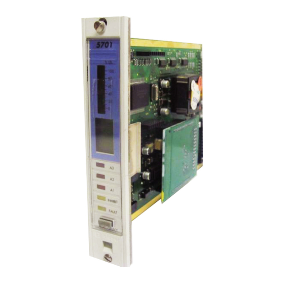
05701-M-5001 A02279 CHAPTER 2 - SYSTEM DESCRIPTION SINGLE CHANNEL CONTROL CARDS General The 5701 Single Channel Control Card provides control, display and alarm facilities for a connected gas detector. The front panel display indicates the gas reading and channel status 5701 while LEDs are used for alarms. -
Page 22: Single Channel Control Card
MAN0443.P65 Issue 13 Aug 04 5701 Control System 05701-M-5001 A02279 CHAPTER 2 - SYSTEM DESCRIPTION Single Channel Control Card The Single Channel Control Card carries out the control functions for a single loop of gas detection as follows: Processes the incoming sensor drive module signal. -
Page 23: Single Channel Control Card Physical Layout
MAN0443.P65 Issue 13 Aug 04 5701 Control System 05701-M-5001 A02279 CHAPTER 2 - SYSTEM DESCRIPTION Single Channel Control Card Physical Layout The physical layout of the Single Channel Control Card is shown below. The Sensor Drive Modules plug into the 14-way connectors J1 and J2 while the Analogue Output Module, when fitted, plugs into J3 and J4. -
Page 24: Field Interface And Relay Cards
MAN0443.P65 Issue 13 Aug 04 5701 Control System 05701-M-5001 A02279 CHAPTER 2 - SYSTEM DESCRIPTION FIELD INTERFACE AND RELAY CARDS General The Field Interface Card and the four types of relay card provide the interface between a Single Channel Control Card and the field wiring. - Page 25 MAN0443.P65 Issue 13 Aug 04 5701 Control System 05701-M-5001 A02279 CHAPTER 2 - SYSTEM DESCRIPTION 5.2.2 Rear Access Connections Slot Location 26 Ground Ground 28 Sensor 01 Connection Sensor S Connection 30 Not Connected Sensor NS Connection 29 32 Analogue O/P (-)
- Page 26 MAN0443.P65 Issue 13 Aug 04 5701 Control System 05701-M-5001 A02279 CHAPTER 2 - SYSTEM DESCRIPTION 5.2.3 Front Access Connections User Terminal Reference 35 +24V (Out/In) 0V (Out/In) 33 Remote Inhibit In Remote Reset In 31 Analogue O/P (+) Analogue O/P (-)
-
Page 27: Double Spco Relay Card
MAN0443.P65 Issue 13 Aug 04 5701 Control System 05701-M-5001 A02279 CHAPTER 2 - SYSTEM DESCRIPTION Double SPCO Relay Card (Part Number 05701-A-0327) 5.3.1 General Provides connections between the sensor and the control card in the same way as the Field Interface Card. In addition, single pole relays provide voltage free contact outputs for the A1 alarm level, A2 alarm level and fault condition. - Page 28 MAN0443.P65 Issue 13 Aug 04 5701 Control System 05701-M-5001 A02279 CHAPTER 2 - SYSTEM DESCRIPTION 5.3.3 Front Access Connections User Terminal Reference +24V (Out/In) 0V (Out/In) Remote Inhibit In Remote Reset In Analogue O/P (+) Analogue O/P (-) Sensor NS Connection...
-
Page 29: Triple Spco Relay Card
MAN0443.P65 Issue 13 Aug 04 5701 Control System 05701-M-5001 A02279 CHAPTER 2 - SYSTEM DESCRIPTION Triple SPCO Relay Card (Part Number 05701-A-0328) 5.4.1 General Provides connections between the sensor and the control card in the same way as the Field Interface Card. In addition, single pole relays provide voltage free contact outputs for the A1 alarm level, A2 alarm level, A3 alarm level, fault and inhibit conditions. - Page 30 MAN0443.P65 Issue 13 Aug 04 5701 Control System 05701-M-5001 A02279 CHAPTER 2 - SYSTEM DESCRIPTION 5.4.3 Front Access Connections User Terminal Reference +24V (Out/In) 0V (Out/In) Remote Inhibit In Remote Reset In Analogue O/P (-) Analogue O/P (+) Not Connected...
-
Page 31: Triple Dpco Relay Card
MAN0443.P65 Issue 13 Aug 04 5701 Control System 05701-M-5001 A02279 CHAPTER 2 - SYSTEM DESCRIPTION Triple DPCO Relay Card (Part Number 05701-A-0329) 5.5.1 General Provides connections between the sensor and the control card in the same way as the Field Interface Card. In addition, single pole relays provide voltage free contact outputs for 2 x A1 alarm level, 2 x A2 alarm level, 2 x A3 alarm level, fault and inhibit conditions. - Page 32 MAN0443.P65 Issue 13 Aug 04 5701 Control System 05701-M-5001 A02279 CHAPTER 2 - SYSTEM DESCRIPTION 5.5.3 Front Access Connections User Terminal Reference 0V (Out/In) +24V (Out/In) Remote Reset In Remote Inhibit In Analogue O/P (-) Analogue O/P (+) Not Connected...
-
Page 33: High Integrity Relay Card
MAN0443.P65 Issue 13 Aug 04 5701 Control System 05701-M-5001 A02279 CHAPTER 2 - SYSTEM DESCRIPTION High Integrity Relay Card (Part Number 05701-A-0330) 5.6.1 General Provides connections between the sensor and the control card in the same way as the Field Interface Card. This card is used to provide master alarm functions or a mixture of master and individual alarms. - Page 34 MAN0443.P65 Issue 13 Aug 04 5701 Control System 05701-M-5001 A02279 CHAPTER 2 - SYSTEM DESCRIPTION 5.6.2 Rear Access Connections IMPORTANT Refer to configuration printout, or use the Relays Screen of the Engineering Interface Software, to determine the relay function. Slot...
- Page 35 MAN0443.P65 Issue 13 Aug 04 5701 Control System 05701-M-5001 A02279 CHAPTER 2 - SYSTEM DESCRIPTION 5.6.3 Front Access Connections IMPORTANT Refer to configuration printout, or use the Relays Screen of the Engineering Interface Software, to determine the relay function. User...
-
Page 36: Engineering Card
MAN0443.P65 Issue 13 Aug 04 5701 Control System 05701-M-5001 A02279 CHAPTER 2 - SYSTEM DESCRIPTION ENGINEERING CARD The Engineering Card (Part Number 05701-A-0361) is used on a System 57 rack to provide a common interface that enables the user to perform all the required functions to commission and operate each fitted control card. - Page 37 MAN0443.P65 Issue 13 Aug 04 5701 Control System 05701-M-5001 A02279 CHAPTER 2 - SYSTEM DESCRIPTION One of four optional modules may be fitted to the Engineering Card: Master Alarm Update Module This facility provides an indication when a new alarm occurs on any channel in the rack, even if a previous alarm condition already exists.
-
Page 38: Dc Input Card
MAN0443.P65 Issue 13 Aug 04 5701 Control System 05701-M-5001 A02279 CHAPTER 2 - SYSTEM DESCRIPTION DC INPUT CARD General The dc power to the rack normally enters the sub-rack via the DC Input Card (Part Number 05701-A-0325). This power may be supplied by the user from an external nominal 24V dc supply. -
Page 39: Rear Access Connections
MAN0443.P65 Issue 13 Aug 04 5701 Control System 05701-M-5001 A02279 CHAPTER 2 - SYSTEM DESCRIPTION Rear Access Connections User Terminal Reference 12 +24V In (PSU 1) 11 0V In (PSU 1) 10 +24V In (PSU 2*) or +24V Out (PSU 1) -
Page 40: Front Access Connections
MAN0443.P65 Issue 13 Aug 04 5701 Control System 05701-M-5001 A02279 CHAPTER 2 - SYSTEM DESCRIPTION Front Access Connections Slot Location Connections to the Engineering Card optional modules. Functions vary depending upon type of module fitted. Ground Ground 0V Out (Fused) -
Page 41: Ac To Dc Power Supply Units
MAN0443.P65 Issue 13 Aug 04 5701 Control System 05701-M-5001 A02279 CHAPTER 2 - SYSTEM DESCRIPTION AC TO DC POWER SUPPLY UNITS Types of Power Supply Unit There are two types of AC to DC power supply units: 8-Way AC to DC Power Supply Unit (Part Number 05701-A-0406) A 1U high half width 19 inch rack mounted unit that contains a single 50W Switched Mode AC to DC Power Supply Module. -
Page 42: 8-Way Ac To Dc Power Supply Unit Layout
MAN0443.P65 Issue 13 Aug 04 5701 Control System 05701-M-5001 A02279 CHAPTER 2 - SYSTEM DESCRIPTION 8-Way AC to DC Power Supply Unit Layout Front View Top View Rear View Input ac 24V dc Output Voltage. Supply Voltage 50W per Fitted Module... -
Page 43: 50W Sub-Unit Layout
MAN0443.P65 Issue 13 Aug 04 5701 Control System 05701-M-5001 A02279 CHAPTER 2 - SYSTEM DESCRIPTION 50W Sub-Unit Layout The 50W Sub-unit is fitted with a single 50W Switched Mode AC to DC Power Supply Module as shown below: Top View... -
Page 44: Front Panel Blanking Panel
MAN0443.P65 Issue 13 Aug 04 5701 Control System 05701-M-5001 A02279 CHAPTER 2 - SYSTEM DESCRIPTION FRONT PANEL BLANKING PANEL Matching blank front panels are available for fitting to the rack in all unused single channel control card spaces. 2 - 31... - Page 45 MAN0443.P65 Issue 13 Aug 04 5701 Control System 05701-M-5001 A02279 CHAPTER 2 - SYSTEM DESCRIPTION 2 - 32...
-
Page 46: Controls And Facilities
MAN0443.P65 Issue 13 Aug 04 5701 Control System 05701-M-5001 A02279 CHAPTER 3 CONTROLS AND FACILITIES 5701 SERIES CONTROL SYSTEM CHAPTER 3 CONTROLS AND FACILITIES 3 - 1... - Page 47 MAN0443.P65 Issue 13 Aug 04 5701 Control System 05701-M-5001 A02279 CHAPTER 3 CONTROLS AND FACILITIES CONTENTS Section Page INTRODUCTION SINGLE CHANNEL CONTROL CARD 2.1 General 2.2 Liquid Crystal Display 2.3 LEDs 3-11 2.4 Reset/Select Push-button 3-12 2.5 Extraction Slot 3-13 2.6 Display Label and Cover...
-
Page 48: Introduction
05701-M-5001 A02279 CHAPTER 3 CONTROLS AND FACILITIES INTRODUCTION The 5701 Series Control System is equipped to provide the operational and engineering facilities necessary to fully maintain a system of gas detection equipment. Each control card within a rack system displays a sensor reading, alarm status and condition of that channel. - Page 49 MAN0443.P65 Issue 13 Aug 04 5701 Control System 05701-M-5001 A02279 CHAPTER 3 CONTROLS AND FACILITIES LTEL Alarm (Long Term Exposure Limit). The LTEL alarm will be activated when the time weighted average concentration of a toxic gas, usually averaged over 8 hours, crosses a preconfigured threshold.
- Page 50 MAN0443.P65 Issue 13 Aug 04 5701 Control System 05701-M-5001 A02279 CHAPTER 3 CONTROLS AND FACILITIES Voted Alarm* A voted alarm is caused by the simultaneous presence of an identical alarm on more than one control channel within a preconfigured group.
- Page 51 MAN0443.P65 Issue 13 Aug 04 5701 Control System 05701-M-5001 A02279 CHAPTER 3 CONTROLS AND FACILITIES Falling Alarm A falling alarm is caused by a falling level of the parameter being measured crossing a preconfigured threshold and will also cause the associated alarm LED to illuminate.
- Page 52 Control Card Versions Since the original launch of System 57 several new features have been added to enhance the capabilities of the 5701 Control Card. The key features for each software version are illustrated in the following table. Note that the software fitted to existing cards cannot...
-
Page 53: Single Channel Control Card
MAN0443.P65 Issue 13 Aug 04 5701 Control System 05701-M-5001 A02279 CHAPTER 3 CONTROLS AND FACILITIES SINGLE CHANNEL CONTROL CARD General The Single Channel Control Card provides the necessary power supplies to the associated sensor and conditions the incoming sensor 5701 signal. -
Page 54: Liquid Crystal Display
MAN0443.P65 Issue 13 Aug 04 5701 Control System 05701-M-5001 A02279 CHAPTER 3 CONTROLS AND FACILITIES Liquid Crystal Display 2.2.1 General The LCD provides a display of the connected sensor reading and its status, or if maintenance is being carried out on the sensor, information on the 5701 sensor set points and calibration data. - Page 55 MAN0443.P65 Issue 13 Aug 04 5701 Control System 05701-M-5001 A02279 CHAPTER 3 CONTROLS AND FACILITIES 2.2.3 Digital Display The digital display is a four character, seven segment display which provides either an indication of the sensor gas reading or a value relating to a function selected from the Engineering Card.
-
Page 56: Leds
MAN0443.P65 Issue 13 Aug 04 5701 Control System 05701-M-5001 A02279 CHAPTER 3 CONTROLS AND FACILITIES LEDS Five LEDs on the front panel of the control card indicate the operational status of the channel as follows: FAULT - Amber LED The fault LED provides an indication in the event of a sensor hardware failure, if the sensor signal is outside pre-defined limits or if the channel card has detected a hardware or software fault. -
Page 57: Reset/Select Push-Button
MAN0443.P65 Issue 13 Aug 04 5701 Control System 05701-M-5001 A02279 CHAPTER 3 CONTROLS AND FACILITIES Reset/Select Push-button The front panel RESET/SELECT push-button provides four functions depending upon how it is operated: Alarm Reset The RESET/SELECT push-button, when pressed momentarily, resets... -
Page 58: Extraction Slot
MAN0443.P65 Issue 13 Aug 04 5701 Control System 05701-M-5001 A02279 CHAPTER 3 CONTROLS AND FACILITIES Extraction Slot An extraction tool is used in conjunction with the extraction slot, just below the select push-button, to remove the card from the rack. The extraction tool is provided as part of the Key Kit (05701-A-0550) supplied with each rack assembly. -
Page 59: Engineering Card
MAN0443.P65 Issue 13 Aug 04 5701 Control System 05701-M-5001 A02279 CHAPTER 3 CONTROLS AND FACILITIES ENGINEERING CARD General The Engineering Card provides facilities to allow each control card to be interrogated and to allow normal maintenance functions such as calibration to be carried out. It also acts as a connecting point for the engineering interface which allows each card to be configured. -
Page 60: Engineering Push-Buttons
MAN0443.P65 Issue 13 Aug 04 5701 Control System 05701-M-5001 A02279 CHAPTER 3 CONTROLS AND FACILITIES Engineering Push-buttons 3.3.1 General The Engineering Card push-buttons control various functions depending on the type of control card fitted and whether the Engineering Key is fitted. - Page 61 MAN0443.P65 Issue 13 Aug 04 5701 Control System 05701-M-5001 A02279 CHAPTER 3 CONTROLS AND FACILITIES 3.3.8 ALARMS Push-button When the ALARMS push-button is operated, the display of the selected control card provides an indication of that card's level and type (rising or falling) of each alarm level (A1, A2, A3, STEL, LTEL).
- Page 62 MAN0443.P65 Issue 13 Aug 04 5701 Control System 05701-M-5001 A02279 CHAPTER 3 CONTROLS AND FACILITIES The rack clock is located in the Engineering Card, however since the Engineering Card has no display, a control card must be selected to enable the time and date to be displayed. It does not matter which control card is selected.
- Page 63 MAN0443.P65 Issue 13 Aug 04 5701 Control System 05701-M-5001 A02279 CHAPTER 3 CONTROLS AND FACILITIES 3 - 18...
-
Page 64: Installation Instructions
MAN0443.P65 Issue 13 Aug 04 5701 Control System 05701-M-5001 A02279 CHAPTER 4 - INSTALLATION INSTRUCTIONS 5701 SERIES CONTROL SYSTEM CHAPTER 4 INSTALLATION INSTRUCTIONS 4 - 1... - Page 65 MAN0443.P65 Issue 13 Aug 04 5701 Control System 05701-M-5001 A02279 CHAPTER 4 - INSTALLATION INSTRUCTIONS WARNING For installations in the EU, refer to EN60079-14:1997, ‘Electrical Installations in Hazardous Areas (other than mines). Additionally, the code of practice regarding Selection, installation,...
- Page 66 MAN0443.P65 Issue 13 Aug 04 5701 Control System 05701-M-5001 A02279 CHAPTER 4 - INSTALLATION INSTRUCTIONS CONTENTS Section Page INTRODUCTION UNPACKING LOCATION CABLING POWER REQUIREMENTS VENTILATION 4-11 PRELIMINARIES 4-12 CABINET INSTALLATION 4-13 PANEL INSTALLATION 4-16 RACK INSTALLATION 4-18 SENSOR INSTALLATION 4-19 11.1...
- Page 67 MAN0443.P65 Issue 13 Aug 04 5701 Control System 05701-M-5001 A02279 CHAPTER 4 - INSTALLATION INSTRUCTIONS SENSOR CONNECTIONS 4-25 13.1 General 4-25 13.2 Catalytic Sensor Connections 4-25 13.3 4 - 20mA Loop Powered Sensor Connections 4-28 13.4 4 - 20mA Transmitter Connections 4-31 13.5...
-
Page 68: Introduction
MAN0443.P65 Issue 13 Aug 04 5701 Control System 05701-M-5001 A02279 CHAPTER 4 - INSTALLATION INSTRUCTIONS INTRODUCTION A summary of the System 57 controller installation procedures is shown below: Unpack and check the equipment. Identify a suitable location and check the cabling requirements. -
Page 69: Unpacking
MAN0443.P65 Issue 13 Aug 04 5701 Control System 05701-M-5001 A02279 CHAPTER 4 - INSTALLATION INSTRUCTIONS UNPACKING On receipt: Carefully unpack the equipment observing any instructions printed on or contained in the packaging. Check the contents for transit damage and against the packing note for deficiencies. -
Page 70: Location
MAN0443.P65 Issue 13 Aug 04 5701 Control System 05701-M-5001 A02279 CHAPTER 4 - INSTALLATION INSTRUCTIONS LOCATION The control system must be installed in a safe area such as a control or equipment room, away from sources of heat, with adequate ventilation and protected from the weather. -
Page 71: Cabling
MAN0443.P65 Issue 13 Aug 04 5701 Control System 05701-M-5001 A02279 CHAPTER 4 - INSTALLATION INSTRUCTIONS CABLING The field terminals on the Field Interface and Relay Cards accept up to 2.5mm˝ single or multi-stranded wire. Cables should be routed carefully to avoid physical and environmental hazards such as mechanical stress and high temperatures. -
Page 72: Power Requirements
MAN0443.P65 Issue 13 Aug 04 5701 Control System 05701-M-5001 A02279 CHAPTER 4 - INSTALLATION INSTRUCTIONS POWER REQUIREMENTS The System 57 operates from a nominal 24V (18V to 32V) dc power supply input which can be derived from various sources including the mains ac, via a separate ac to dc power supply unit, local plant dc supply and/or battery backup dc supply. - Page 73 MAN0443.P65 Issue 13 Aug 04 5701 Control System 05701-M-5001 A02279 CHAPTER 4 - INSTALLATION INSTRUCTIONS Device or Sensor Type Number Unit Total in Rack Requirement Power System 57 Devices: Single Channel Control Card, Catalytic (includes bridge drive at 200mA) ____ 3.75...
-
Page 74: Ventilation
MAN0443.P65 Issue 13 Aug 04 5701 Control System 05701-M-5001 A02279 CHAPTER 4 - INSTALLATION INSTRUCTIONS VENTILATION The System 57 Control System provides the facility for a large number of channels in a very small space. In heavily populated racks, especially... -
Page 75: Preliminaries
MAN0443.P65 Issue 13 Aug 04 5701 Control System 05701-M-5001 A02279 CHAPTER 4 - INSTALLATION INSTRUCTIONS PRELIMINARIES Ensure that each control card is compatible with the proposed sensor/ transmitter to be connected to that control card. Ensure that where an AC to DC Power Supply Unit is to be used, this is compatible with the local mains ac supply voltage and that the PSU power rating is adequate for its individual system load. -
Page 76: Cabinet Installation
MAN0443.P65 Issue 13 Aug 04 5701 Control System 05701-M-5001 A02279 CHAPTER 4 - INSTALLATION INSTRUCTIONS CABINET INSTALLATION Two cabinets are available, an 8-way to accommodate the 8-way front access rack and a 16-way to accommodate the 16-way front access rack. - Page 77 MAN0443.P65 Issue 13 Aug 04 5701 Control System 05701-M-5001 A02279 CHAPTER 4 - INSTALLATION INSTRUCTIONS Cabinet Dimensions: 8 way 337 16 way 540 All dimension shown in mm. Wall Mounting Bracket Hole Locations Cabinet Mounting Brackets 8 way 16 way All dimension shown in mm.
- Page 78 MAN0443.P65 Issue 13 Aug 04 5701 Control System 05701-M-5001 A02279 CHAPTER 4 - INSTALLATION INSTRUCTIONS 16 Channel Cabinet Installation Blanking Panel 16-Way AC to DC Power Supply Unit Channel Cards Engineering Card Interface/Relay DC Input Card Cards Accessory Plate (suitable for mounting DIN rails, circuit breakers, relays, etc.)
-
Page 79: Panel Installation
MAN0443.P65 Issue 13 Aug 04 5701 Control System 05701-M-5001 A02279 CHAPTER 4 - INSTALLATION INSTRUCTIONS PANEL INSTALLATION All racks and the AC to DC Power Supply Units are suitable for panel installation and are installed as follows: Cut out a suitable aperture to accommodate the System 57 rack... - Page 80 MAN0443.P65 Issue 13 Aug 04 5701 Control System 05701-M-5001 A02279 CHAPTER 4 - INSTALLATION INSTRUCTIONS AC to DC PSU Table of Sizes (mm) 43.6 31.8 PSU Assembly Clearance Width Height 8 Way 279.4 261.9 16 Way 482.6 465.1 Insert the rack into the aperture and secure using M6, or similar bolts, through the four mounting holes located upon the front flange plates.
-
Page 81: Rack Installation
MAN0443.P65 Issue 13 Aug 04 5701 Control System 05701-M-5001 A02279 CHAPTER 4 - INSTALLATION INSTRUCTIONS RACK INSTALLATION The 16-way 3U high rear access and 6U high front access racks are suitable for mounting in standard 19" (483mm) wide Mounting Frames. -
Page 82: Sensor Installation
MAN0443.P65 Issue 13 Aug 04 5701 Control System 05701-M-5001 A02279 CHAPTER 4 - INSTALLATION INSTRUCTIONS SENSOR INSTALLATION 11.1 General Always install the sensors in accordance with the Sensor Operating Instructions. In general, sensors for lighter than air gasses should be located at a high level and sensors for heavier than air gasses should be located at a low level. - Page 83 MAN0443.P65 Issue 13 Aug 04 5701 Control System 05701-M-5001 A02279 CHAPTER 4 - INSTALLATION INSTRUCTIONS Sensor Line Resistance Maximum Cable Length (m) Device or Sensor Type Conductor Cross Sectional Area (mm˝) 0.50 0.75 1.00 1.50 2.50 704/705 1000 1500 2500...
-
Page 84: 11.3 Cable Resistance Guide
MAN0443.P65 Issue 13 Aug 04 5701 Control System 05701-M-5001 A02279 CHAPTER 4 - INSTALLATION INSTRUCTIONS 11.3 Cable Resistance Guide A guide to the resistance of various copper cable sizes is given below: Solid Copper Conductor Cross Sectional Area (mm˝) Maximum resistance at 20°C (ohm/km) 0.50... -
Page 85: 11.5 4-20Ma Loop Powered Sensors
MAN0443.P65 Issue 13 Aug 04 5701 Control System 05701-M-5001 A02279 CHAPTER 4 - INSTALLATION INSTRUCTIONS 11.5 4-20mA Loop Powered Sensors: The maximum line resistance of cabling for a 4 - 20mA loop powered sensor varies with the voltage drive requirements of the type of sensor installed. -
Page 86: Control Card Sensor Drive Module Configuration
MAN0443.P65 Issue 13 Aug 04 5701 Control System 05701-M-5001 A02279 CHAPTER 4 - INSTALLATION INSTRUCTIONS CONTROL CARD SENSOR DRIVE MODULE CONFIGURATION 12.1 General The sensor drive modules fitted to the Single Channel Control Cards have configuration links that effect the operation of the sensor. The following sections identify the links to allow the configuration to be inspected. - Page 87 MAN0443.P65 Issue 13 Aug 04 5701 Control System 05701-M-5001 A02279 CHAPTER 4 - INSTALLATION INSTRUCTIONS be accommodated. A link is closed by fitting the jumper provided so that the two pins of the link are connected. Unused links should have their...
- Page 88 MAN0443.P65 Issue 13 Aug 04 5701 Control System 05701-M-5001 A02279 CHAPTER 4 - INSTALLATION INSTRUCTIONS SENSOR CONNECTIONS 13.1 General WARNING Incorrect connection of the sensor wires may cause damage to both the sensor and System 57. CAUTION The sensors connections must always be made with the System 57 unit in an unpowered state.
- Page 89 MAN0443.P65 Issue 13 Aug 04 5701 Control System 05701-M-5001 A02279 CHAPTER 4 - INSTALLATION INSTRUCTIONS The sensor cable screen or steel wire armour (or braid), as appropriate, should be connected to the system (protective) earth. This can be achieved where the cable enters the cabinet by using a metal cable gland, or by other suitable means, and avoiding any screen 'tails' within the cabinet.
- Page 90 MAN0443.P65 Issue 13 Aug 04 5701 Control System 05701-M-5001 A02279 CHAPTER 4 - INSTALLATION INSTRUCTIONS Single Channel Control Card Catalytic 05701-A-0302 Fitted with Catalytic Sensor Drive 05701-A-0284 Note: Where a sensor is earthed locally, either to the Earth Stud or through the sensor casing...
- Page 91 MAN0443.P65 Issue 13 Aug 04 5701 Control System 05701-M-5001 A02279 CHAPTER 4 - INSTALLATION INSTRUCTIONS 13.3 4 - 20mA Loop Powered Sensor Connections Loop powered sensors require a two wire connection and the sensor documentation will indicate the positive and negative loop connections, usually brown and blue respectively.
- Page 92 MAN0443.P65 Issue 13 Aug 04 5701 Control System 05701-M-5001 A02279 CHAPTER 4 - INSTALLATION INSTRUCTIONS Single Channel Control Card 4 - 20mA 05701-A-0301 Relay/Field Interface Fitted with 4 - 20mA Sensor Drive 05701-A-0283 Card 05701-A-0326 05701-A-0327 05701-A-0328 05701-A-0329 05701-A-0330 Junction Box...
- Page 93 MAN0443.P65 Issue 13 Aug 04 5701 Control System 05701-M-5001 A02279 CHAPTER 4 - INSTALLATION INSTRUCTIONS Single Channel Control Card 4 - 20mA 05701-A-0301 Relay/Field Interface Fitted with 4 - 20mA Sensor Drive 05701-A-0283 Card 05701-A-0326 05701-A-0327 05701-A-0328 Junction Box 05701-A-0329...
- Page 94 MAN0443.P65 Issue 13 Aug 04 5701 Control System 05701-M-5001 A02279 CHAPTER 4 - INSTALLATION INSTRUCTIONS 13.4 4 - 20mA Transmitter Connections CAUTION The power provided by the Single Channel Control Card is derived from the dc input to the System 57 (18V to 32V). Check that the transmitter to be connected is compatible with the actual supply voltage used.
- Page 95 MAN0443.P65 Issue 13 Aug 04 5701 Control System 05701-M-5001 A02279 CHAPTER 4 - INSTALLATION INSTRUCTIONS Single Channel Control Card 4 - 20mA 05701-A-0301 Relay/Field Interface Card Fitted with 4 - 20mA Sensor Drive 05701-A-0283 05701-A-0326 05701-A-0327 05701-A-0328 Opus/Lifeline II Transmitter...
- Page 96 MAN0443.P65 Issue 13 Aug 04 5701 Control System 05701-M-5001 A02279 CHAPTER 4 - INSTALLATION INSTRUCTIONS Relay/Field Interface Card Single Channel Control Card 4 - 20mA 05701-A-0301 05701-A-0326 Fitted with 4 - 20mA Sensor Drive 05701-A-0283 05701-A-0327 05701-A-0328 05701-A-0329 Opus/Lifeline II Transmitter...
- Page 97 MAN0443.P65 Issue 13 Aug 04 5701 Control System 05701-M-5001 A02279 CHAPTER 4 - INSTALLATION INSTRUCTIONS Relay/Field Interface Card Single Channel Control Card 4 - 20mA 05701-A-0301 05701-A-0326 Fitted with 4 - 20mA Sensor Drive 05701-A-0283 05701-A-0327 05701-A-0328 05701-A-0329 05701-A-0330 Opus/Lifeline II Transmitter...
- Page 98 MAN0443.P65 Issue 13 Aug 04 5701 Control System 05701-M-5001 A02279 CHAPTER 4 - INSTALLATION INSTRUCTIONS Apex Transmitter Single Channel Control Card 4 - 20mA 05701-A-0301 Relay/Field Interface Card Fitted with 4 - 20mA Sensor Drive 05701-A-0283 05701-A-0326 05701-A-0327 05701-A-0328 05701-A-0329...
- Page 99 MAN0443.P65 Issue 13 Aug 04 5701 Control System 05701-M-5001 A02279 CHAPTER 4 - INSTALLATION INSTRUCTIONS Apex Transmitter Relay/Field Interface Card Single Channel Control Card 4 - 20mA 05701-A-0301 05701-A-0326 Fitted with 4 - 20mA Sensor Drive 05701-A-0283 05701-A-0327 05701-A-0328 05701-A-0329...
- Page 100 MAN0443.P65 Issue 13 Aug 04 5701 Control System 05701-M-5001 A02279 CHAPTER 4 - INSTALLATION INSTRUCTIONS Relay/Field Interface Card Single Channel Control Card 4 - 20mA 05701-A-0301 05701-A-0326 Fitted with 4 - 20mA Sensor Drive 05701-A-0283 05701-A-0327 Apex Transmitter 05701-A-0328 05701-A-0329...
- Page 101 MAN0443.P65 Issue 13 Aug 04 5701 Control System 05701-M-5001 A02279 CHAPTER 4 - INSTALLATION INSTRUCTIONS Single Channel Control Card 4 - 20mA 05701-A-0301 Relay/Field Interface Card Fitted with 4 - 20mA Sensor Drive 05701-A-0283 05701-A-0326 05701-A-0327 05701-A-0328 05701-A-0329 05701-A-0330 Series 2000...
- Page 102 MAN0443.P65 Issue 13 Aug 04 5701 Control System 05701-M-5001 A02279 CHAPTER 4 - INSTALLATION INSTRUCTIONS Relay/Field Interface Card Single Channel Control Card 4 - 20mA 05701-A-0301 05701-A-0326 Fitted with 4 - 20mA Sensor Drive 05701-A-0283 05701-A-0327 05701-A-0328 05701-A-0329 05701-A-0330 Series 2000...
- Page 103 MAN0443.P65 Issue 13 Aug 04 5701 Control System 05701-M-5001 A02279 CHAPTER 4 - INSTALLATION INSTRUCTIONS Single Channel Control Card 4 - 20mA 05701-A-0301 Relay/Field Interface Card 05701-A-0326 Fitted with 4 - 20mA Sensor Drive 05701-A-0283 05701-A-0327 05701-A-0328 Junction 05701-A-0329 Searchpoint Optima...
- Page 104 MAN0443.P65 Issue 13 Aug 04 5701 Control System 05701-M-5001 A02279 CHAPTER 4 - INSTALLATION INSTRUCTIONS Single Channel Control Card 4 - 20mA 05701-A-0301 Relay/Field Interface Card Fitted with 4 - 20mA Sensor Drive 05701-A-0283 05701-A-0326 05701-A-0327 05701-A-0328 Junction Terminal 05701-A-0329...
- Page 105 MAN0443.P65 Issue 13 Aug 04 5701 Control System 05701-M-5001 A02279 CHAPTER 4 - INSTALLATION INSTRUCTIONS Single Channel Control Card 4 - 20mA 05701-A-0301 Relay/Field Interface Card Fitted with 4 - 20mA Sensor Drive 05701-A-0283 05701-A-0326 05701-A-0327 05701-A-0328 05701-A-0329 05701-A-0330 Connections using a...
- Page 106 MAN0443.P65 Issue 13 Aug 04 5701 Control System 05701-M-5001 A02279 CHAPTER 4 - INSTALLATION INSTRUCTIONS Single Channel Control Card 4 - 20mA 05701-A-0301 Fitted with 4 - 20mA Sensor Drive 05701-A-0283 Relay/Field Interface Card 05701-A-0326 05701-A-0327 05701-A-0328 05701-A-0329 05701-A-0330 Searchline Excel Cross Duct...
- Page 107 MAN0443.P65 Issue 13 Aug 04 5701 Control System 05701-M-5001 A02279 CHAPTER 4 - INSTALLATION INSTRUCTIONS Single Channel Control Card 4 - 20mA 05701-A-0301 Fitted with 4 - 20mA Sensor Drive 05701-A-0283 Relay/Field Interface Card 05701-A-0326 05701-A-0327 05701-A-0328 05701-A-0329 Searchline Excel Cross Duct...
- Page 108 MAN0443.P65 Issue 13 Aug 04 5701 Control System 05701-M-5001 A02279 CHAPTER 4 - INSTALLATION INSTRUCTIONS Single Channel Control Card 4 - 20mA 05701-A-0301 Fitted with 4 - 20mA Sensor Drive 05701-A-0283 Link Positions LK12 Note: 1. Where a sensor is earthed locally, either to the Earth Stud or...
- Page 109 MAN0443.P65 Issue 13 Aug 04 5701 Control System 05701-M-5001 A02279 CHAPTER 4 - INSTALLATION INSTRUCTIONS Single Channel Control Card 4 - 20mA 05701-A-0301 Fitted with 4 - 20mA Sensor Drive 05701-A-0283 Link Positions LK12 LK10 Note: 1. Where a sensor is earthed locally, either to the Earth Stud or...
- Page 110 MAN0443.P65 Issue 13 Aug 04 5701 Control System 05701-M-5001 A02279 CHAPTER 4 - INSTALLATION INSTRUCTIONS Single Channel Control Card 4 - 20mA 05701-A-0301 Relay/Field Interface Card Fitted with 4 - 20mA Sensor Drive 05701-A-0283 05701-A-0326 05701-A-0327 05701-A-0328 05701-A-0329 05701-A-0330 Searchpoint 500...
- Page 111 MAN0443.P65 Issue 13 Aug 04 5701 Control System 05701-M-5001 A02279 CHAPTER 4 - INSTALLATION INSTRUCTIONS Single Channel Control Card 4 - 20mA 05701-A-0301 Relay/Field Interface Card Fitted with 4 - 20mA Sensor Drive 05701-A-0283 05701-A-0326 05701-A-0327 05701-A-0328 05701-A-0329 05701-A-0330 Searchpoint 500...
- Page 112 MAN0443.P65 Issue 13 Aug 04 5701 Control System 05701-M-5001 A02279 CHAPTER 4 - INSTALLATION INSTRUCTIONS Single Channel Control Card 4 - 20mA 05701-A-0301 Relay/Field Interface Card Fitted with 4 - 20mA Sensor Drive 05701-A-0283 05701-A-0326 05701-A-0327 05701-A-0328 05701-A-0329 Searchline 500...
- Page 113 MAN0443.P65 Issue 13 Aug 04 5701 Control System 05701-M-5001 A02279 CHAPTER 4 - INSTALLATION INSTRUCTIONS Single Channel Control Card 4 - 20mA 05701-A-0301 Relay/Field Interface Card Fitted with 4 - 20mA Sensor Drive 05701-A-0283 05701-A-0326 05701-A-0327 05701-A-0328 05701-A-0329 05701-A-0330 Arrows Indicate...
- Page 114 MAN0443.P65 Issue 13 Aug 04 5701 Control System 05701-M-5001 A02279 CHAPTER 4 - INSTALLATION INSTRUCTIONS Single Channel Control Card 4 - 20mA 05701-A-0301 Relay/Field Interface Card Fitted with 4 - 20mA Sensor Drive 05701-A-0283 05701-A-0326 05701-A-0327 05701-A-0328 05701-A-0329 05701-A-0330 Arrows Indicate Direction of...
- Page 115 MAN0443.P65 Issue 13 Aug 04 5701 Control System 05701-M-5001 A02279 CHAPTER 4 - INSTALLATION INSTRUCTIONS Single Channel Control Card 4 - 20mA 05701-A-0301 Relay/Field Interface Card Fitted with 4 - 20mA Sensor Drive 05701-A-0283 05701-A-0326 05701-A-0327 05701-A-0328 05701-A-0329 05701-A-0330 Arrows Indicate Direction of...
- Page 116 MAN0443.P65 Issue 13 Aug 04 5701 Control System 05701-M-5001 A02279 CHAPTER 4 - INSTALLATION INSTRUCTIONS Relay/Field Interface Card Single Channel Control Card 4 - 20mA 05701-A-0301 05701-A-0326 Fitted with 4 - 20mA Sensor Drive 05701-A-0283 05701-A-0327 05701-A-0328 05701-A-0329 05701-A-0330 Cabinet...
- Page 117 MAN0443.P65 Issue 13 Aug 04 5701 Control System 05701-M-5001 A02279 CHAPTER 4 - INSTALLATION INSTRUCTIONS Single Channel Control Card 4 - 20mA 05701-A-0301 Relay/Field Interface Card Fitted with 4 - 20mA Sensor Drive 05701-A-0283 05701-A-0326 05701-A-0327 05701-A-0328 05701-A-0329 05701-A-0330 Series 2000 UL...
- Page 118 MAN0443.P65 Issue 13 Aug 04 5701 Control System 05701-M-5001 A02279 CHAPTER 4 - INSTALLATION INSTRUCTIONS Single Channel Control Card 4 - 20mA 05701-A-0301 Relay/Field Interface Card Fitted with 4 - 20mA Sensor Drive 05701-A-0283 05701-A-0326 05701-A-0327 05701-A-0328 05701-A-0329 05701-A-0330 Cabinet...
- Page 119 MAN0443.P65 Issue 13 Aug 04 5701 Control System 05701-M-5001 A02279 CHAPTER 4 - INSTALLATION INSTRUCTIONS 13.5 IS Series 2000 Toxic Transmitter Connections If the measuring resistance is in the positive supply line, a single safety barrier can be used. Relay/Field Interface Card...
- Page 120 MAN0443.P65 Issue 13 Aug 04 5701 Control System 05701-M-5001 A02279 CHAPTER 4 - INSTALLATION INSTRUCTIONS If the measuring resistance is in the negative supply line, a double safety barrier must be used. Relay/Field Interface Card Single Channel Control Card 4 - 20mA 05701-A-0301...
- Page 121 MAN0443.P65 Issue 13 Aug 04 5701 Control System 05701-M-5001 A02279 CHAPTER 4 - INSTALLATION INSTRUCTIONS In this configuration the 4 - 20mA link on the Series 2000 sensor is NOT fitted. Single Channel Control Card 4 - 20mA 05701-A-0301 Relay/Field Interface Card...
- Page 122 MAN0443.P65 Issue 13 Aug 04 5701 Control System 05701-M-5001 A02279 CHAPTER 4 - INSTALLATION INSTRUCTIONS If the measuring resistance is in the positive supply line, a single safety barrier can be used. Single Channel Control Card 4 - 20mA 05701-A-0301...
- Page 123 MAN0443.P65 Issue 13 Aug 04 5701 Control System 05701-M-5001 A02279 CHAPTER 4 - INSTALLATION INSTRUCTIONS If the measuring resistance is in the negative supply line, a double safety barrier must be used. Single Channel Control Card 4 - 20mA 05701-A-0301...
- Page 124 MAN0443.P65 Issue 13 Aug 04 5701 Control System 05701-M-5001 A02279 CHAPTER 4 - INSTALLATION INSTRUCTIONS OUTPUT CONNECTIONS 14.1 Relay Outputs Note: 1. The FAULT relay is permanently configured for normally ENERGISED operation in the non-fault condition. 2. Unless the High Integrity Relay Card is fitted, the INHIBIT relay (where fitted) is permanently configured for normally DE-ENERGISED operation in the non-inhibit condition.
- Page 125 MAN0443.P65 Issue 13 Aug 04 5701 Control System 05701-M-5001 A02279 CHAPTER 4 - INSTALLATION INSTRUCTIONS The alarm relays may be configured for either normally de-energised or normally energised operation. Check the configuration sheet supplied with the system to determine the operating mode of the relays on each channel.
- Page 126 MAN0443.P65 Issue 13 Aug 04 5701 Control System 05701-M-5001 A02279 CHAPTER 4 - INSTALLATION INSTRUCTIONS The analogue output can be configured for 0 - 20mA or 4 - 20mA output modes. Check the configuration sheet supplied with the system to determine the factory configured operating mode.
- Page 127 MAN0443.P65 Issue 13 Aug 04 5701 Control System 05701-M-5001 A02279 CHAPTER 4 - INSTALLATION INSTRUCTIONS Single Channel Control Card Fitted with Analogue Output 05701-A-0301 4 - 20mA Module 05701-A-0285 05701-A-0302 Catalytic Relay/Field Interface Card 05701-A-0326 05701-A-0327 05701-A-0328 05701-A-0329 05701-A-0330 Analogue O/P+...
- Page 128 MAN0443.P65 Issue 13 Aug 04 5701 Control System 05701-M-5001 A02279 CHAPTER 4 - INSTALLATION INSTRUCTIONS REMOTE INPUT CONNECTIONS CAUTION Connecting voltages in excess of 32V to the remote inputs may cause permanent damage to the Single Channel Control Card. There are two remote inputs, RESET and INHIBIT, which are individually configurable for active high or active low operating modes.
- Page 129 MAN0443.P65 Issue 13 Aug 04 5701 Control System 05701-M-5001 A02279 CHAPTER 4 - INSTALLATION INSTRUCTIONS Single Channel Control Card Configured for active 05701-A-0301 4 - 20mA high remote inputs 05701-A-0302 Catalytic Relay/Field Interface Card 05701-A-0326 05701-A-0327 05701-A-0328 05701-A-0329 05701-A-0330 Normally Open Contact...
- Page 130 MAN0443.P65 Issue 13 Aug 04 5701 Control System 05701-M-5001 A02279 CHAPTER 4 - INSTALLATION INSTRUCTIONS DC POWER CONNECTIONS 16.1 General CAUTION The ratings of power supplies should be checked by calculating a system power budget as outlined in Section 5.
- Page 131 MAN0443.P65 Issue 13 Aug 04 5701 Control System 05701-M-5001 A02279 CHAPTER 4 - INSTALLATION INSTRUCTIONS 16.2 Individually Powered Control Cards Note: In individually powered control systems a DC connection is still required to the DC Input Card in order to provide power to the Engineering Card.
- Page 132 MAN0443.P65 Issue 13 Aug 04 5701 Control System 05701-M-5001 A02279 CHAPTER 4 - INSTALLATION INSTRUCTIONS AC TO DC POWER SUPPLY UNIT CONNECTIONS WARNING The AC to DC Power Supply Unit must be earthed. The input supply to the AC to DC Power Supply Unit may be: an ac supply of 85V to 264V at 47Hz to 440Hz.
- Page 133 MAN0443.P65 Issue 13 Aug 04 5701 Control System 05701-M-5001 A02279 CHAPTER 4 - INSTALLATION INSTRUCTIONS AC to DC PSU AC to DC PSU 50W Sub-Unit 50W Sub-Unit Earth Earth AC Input Stud Stud System Supply Earth Brown Blue Green/Yellow DC Input Card...
- Page 134 MAN0443.P65 Issue 13 Aug 04 5701 Control System 05701-M-5001 A02279 CHAPTER 4 - INSTALLATION INSTRUCTIONS UPGRADING THE AC TO DC POWER SUPPLY UNITS WARNING High voltages exist within the AC to DC Power Supply Unit. Disconnect from the ac supply for a period of at least five minutes before removing the top cover and carrying out any maintenance or upgrade operation.
- Page 135 MAN0443.P65 Issue 13 Aug 04 5701 Control System 05701-M-5001 A02279 CHAPTER 4 - INSTALLATION INSTRUCTIONS Front View 50W Switched Mode AC to DC Power Supply Module Top View 50W Switched Mode AC to DC Power Supply Module Rear View Input AC...
- Page 136 MAN0443.P65 Issue 13 Aug 04 5701 Control System 05701-M-5001 A02279 CHAPTER 4 - INSTALLATION INSTRUCTIONS Front View 50W Switched Mode AC to DC Power Supply Module Top View 50W Switched Mode AC to DC Power Supply Module Rear View Input AC...
- Page 137 MAN0443.P65 Issue 13 Aug 04 5701 Control System 05701-M-5001 A02279 CHAPTER 4 - INSTALLATION INSTRUCTIONS Front View 50W Switched Mode AC to DC 50W Switched Mode AC to DC Power Supply Module Power Supply Module Top View 50W Switched Mode AC to DC...
- Page 138 MAN0443.P65 Issue 13 Aug 04 5701 Control System 05701-M-5001 A02279 CHAPTER 4 - INSTALLATION INSTRUCTIONS Insert the module, with the same orientation as the already fitted module, into the vacant position inside the 50W Sub Unit and secure using the washers and long nuts retained in Step (3).
- Page 139 MAN0443.P65 Issue 13 Aug 04 5701 Control System 05701-M-5001 A02279 CHAPTER 4 - INSTALLATION INSTRUCTIONS 4 - 76...
- Page 140 MAN0443.P65 Issue 13 Aug 04 5701 Control System 05701-M-5001 A02279 CHAPTER 5 - COMMISSIONING AND MAINTENANCE INSTRUCTIONS 5701 SERIES CONTROL SYSTEM CHAPTER 5 COMMISSIONING AND MAINTENANCE INSTRUCTIONS 5 - 1...
- Page 141 MAN0443.P65 Issue 13 Aug 04 5701 Control System 05701-M-5001 A02279 CHAPTER 5 - COMMISSIONING AND MAINTENANCE INSTRUCTIONS CONTENTS Section Page GENERAL START UP PROCEDURE CALIBRATION MAINTENANCE ERROR CODES 5.1 General 5.2 Self Test Faults 5.3 Run Time Errors 5-11 5.4 Calibration Errors 5-14 5.5 System Errors...
-
Page 142: General
MAN0443.P65 Issue 13 Aug 04 5701 Control System 05701-M-5001 A02279 CHAPTER 5 - COMMISSIONING AND MAINTENANCE INSTRUCTIONS WARNING High ac mains voltages may be present at the system power supply unit and at the relay terminals of the interface cards. Appropriate safety precautions must be taken when commissioning or servicing the system. -
Page 143: Start Up Procedure
MAN0443.P65 Issue 13 Aug 04 5701 Control System 05701-M-5001 A02279 CHAPTER 5 - COMMISSIONING AND MAINTENANCE INSTRUCTIONS START UP PROCEDURE A detailed check of the system wiring should be carried out prior to this start-up procedure. Start-up the system as follows: Ensure that the system power supply is switched off. - Page 144 MAN0443.P65 Issue 13 Aug 04 5701 Control System 05701-M-5001 A02279 CHAPTER 5 - COMMISSIONING AND MAINTENANCE INSTRUCTIONS (14) Check the operation of the connected sensor by checking the BEAD mA and mV SIGNAL for a catalytic sensor or the mA SIGNAL for a 4 - 20mA sensor.
-
Page 145: Calibration
MAN0443.P65 Issue 13 Aug 04 5701 Control System 05701-M-5001 A02279 CHAPTER 5 - COMMISSIONING AND MAINTENANCE INSTRUCTIONS CALIBRATION Leave the connected sensors to stabilise for a suitable period as specified in the sensor manual. Adjust the sensor head current of catalytic sensors as described in Chapter 7 Section 7 to the required value as indicated in the sensor operating instructions. -
Page 146: Maintenance
MAN0443.P65 Issue 13 Aug 04 5701 Control System 05701-M-5001 A02279 CHAPTER 5 - COMMISSIONING AND MAINTENANCE INSTRUCTIONS MAINTENANCE To ensure that the system functions correctly, maintenance should be carried out on a regular basis as dictated by the site regulations and instructions for the type of sensor being used. -
Page 147: Error Codes
MAN0443.P65 Issue 13 Aug 04 5701 Control System 05701-M-5001 A02279 CHAPTER 5 - COMMISSIONING AND MAINTENANCE INSTRUCTIONS ERROR CODES General Operating errors within the system are indicated on the LCD message display as an error code. The error codes used and their meaning are listed in the following sections. -
Page 148: Self Test Faults
MAN0443.P65 Issue 13 Aug 04 5701 Control System 05701-M-5001 A02279 CHAPTER 5 - COMMISSIONING AND MAINTENANCE INSTRUCTIONS Self Test Faults Error Error Code Meaning Card Fault Latch Code Status Signal RAM Failure. Active RAM stores the working values during operation. - Page 149 MAN0443.P65 Issue 13 Aug 04 5701 Control System 05701-M-5001 A02279 CHAPTER 5 - COMMISSIONING AND MAINTENANCE INSTRUCTIONS Error Error Code Meaning Card Fault Latch Code Status Signal Vps Plug-in Fitted. Active The Vps plug-in is used to set the Vps reference and is not suitable for operating sensors.
-
Page 150: Run Time Errors
MAN0443.P65 Issue 13 Aug 04 5701 Control System 05701-M-5001 A02279 CHAPTER 5 - COMMISSIONING AND MAINTENANCE INSTRUCTIONS Error Error Code Meaning Card Fault Latch Code Status Signal Not applicable High Integrity Relay Fault. Active The actual and demanding states of the high integrity relay outputs do not match. - Page 151 MAN0443.P65 Issue 13 Aug 04 5701 Control System 05701-M-5001 A02279 CHAPTER 5 - COMMISSIONING AND MAINTENANCE INSTRUCTIONS Error Error Code Meaning Card Fault Latch Code Status Signal The reset of a latched signal overrange fault condition should only be carried out after checking that the sensor is in clean (non target gas) air.
- Page 152 MAN0443.P65 Issue 13 Aug 04 5701 Control System 05701-M-5001 A02279 CHAPTER 5 - COMMISSIONING AND MAINTENANCE INSTRUCTIONS Error Error Code Meaning Card Fault Latch Code Status Signal Current Setting Fault (Catalytic Sensors Only) Only Active The current setting fault message is...
-
Page 153: Calibration Errors
MAN0443.P65 Issue 13 Aug 04 5701 Control System 05701-M-5001 A02279 CHAPTER 5 - COMMISSIONING AND MAINTENANCE INSTRUCTIONS Error Error Code Meaning Card Fault Latch Code Status Signal In some instances this error can be caused by short circuits in the sensor or cabling. - Page 154 MAN0443.P65 Issue 13 Aug 04 5701 Control System 05701-M-5001 A02279 CHAPTER 5 - COMMISSIONING AND MAINTENANCE INSTRUCTIONS Error Error Code Meaning Card Fault Latch Code Status Signal If required, this function can be disabled using the Engineering Interface Software configuration program.
- Page 155 MAN0443.P65 Issue 13 Aug 04 5701 Control System 05701-M-5001 A02279 CHAPTER 5 - COMMISSIONING AND MAINTENANCE INSTRUCTIONS Error Error Code Meaning Card Fault Latch Code Status Signal This indicates that the output from the sensor is too low due to either: a.
-
Page 156: System Errors
MAN0443.P65 Issue 13 Aug 04 5701 Control System 05701-M-5001 A02279 CHAPTER 5 - COMMISSIONING AND MAINTENANCE INSTRUCTIONS Error Error Code Meaning Card Fault Latch Code Status Signal Active Calibration Gas Too High The calibration gas too high message is displayed during calibration when the calibration gas is adjusted to a level above the pre-configured level. -
Page 157: Miscellaneous Errors
MAN0443.P65 Issue 13 Aug 04 5701 Control System 05701-M-5001 A02279 CHAPTER 5 - COMMISSIONING AND MAINTENANCE INSTRUCTIONS Error Error Code Meaning Card Fault Latch Code Status Signal Timeout Error Active Backplane command timed out. Reset card by removing power to the card. -
Page 158: Fault Finding
MAN0443.P65 Issue 13 Aug 04 5701 Control System 05701-M-5001 A02279 CHAPTER 5 - COMMISSIONING AND MAINTENANCE INSTRUCTIONS FAULT FINDING The following table provides a guide to diagnosing various conditions within the operation of System 57. Fault Action The Engineering Card front... - Page 159 MAN0443.P65 Issue 13 Aug 04 5701 Control System 05701-M-5001 A02279 CHAPTER 5 - COMMISSIONING AND MAINTENANCE INSTRUCTIONS Action Fault Check the error code tables in Section An error message is 5 for explanation. displayed. Check the message display for an The FAULT LED error code.
- Page 160 MAN0443.P65 Issue 13 Aug 04 5701 Control System 05701-M-5001 A02279 CHAPTER 5 - COMMISSIONING AND MAINTENANCE INSTRUCTIONS Action Fault Check to see if the channel is in the ALARM inhibited condition and if necessary illuminated but there is no remove the inhibit.
- Page 161 MAN0443.P65 Issue 13 Aug 04 5701 Control System 05701-M-5001 A02279 CHAPTER 5 - COMMISSIONING AND MAINTENANCE INSTRUCTIONS 5 - 22...
- Page 162 MAN0443.P65 Issue 13 Aug 04 5701 Control System 05701-M-5001 A02279 CHAPTER 6 - OPERATING INSTRUCTIONS 5701 SERIES CONTROL SYSTEM CHAPTER 6 OPERATING INSTRUCTIONS 6 - 1...
- Page 163 MAN0443.P65 Issue 13 Aug 04 5701 Control System 05701-M-5001 A02279 CHAPTER 6 - OPERATING INSTRUCTIONS CONTENTS Section Page GENERAL USER OPERATING ROUTINES CONTROL CARD 3.1 Reset 3.2 Reset TWA Calculations 3.3 Select 3.4 Deselect ENGINEERING CARD 4.1 General 4.2 Timeout 4.3 Bar Graph Display...
-
Page 164: General
MAN0443.P65 Issue 13 Aug 04 5701 Control System 05701-M-5001 A02279 CHAPTER 6 - OPERATING INSTRUCTIONS GENERAL These operating instructions refer to the facilities available for general operation and interrogation of the system without the Engineering Key fitted. Facilities that may effect the way the system operates are covered in the Engineer's Operating Instructions Chapter 7 which refers to facilities available when the Engineering Key is fitted. -
Page 165: User Operating Routines
MAN0443.P65 Issue 13 Aug 04 5701 Control System 05701-M-5001 A02279 CHAPTER 6 - OPERATING INSTRUCTIONS USER OPERATING ROUTINES Depending upon which keypad function push-buttons are operated, the following user operating routines may be performed: Channel reset. Channel select. View alarm levels. -
Page 166: Control Card
MAN0443.P65 Issue 13 Aug 04 5701 Control System 05701-M-5001 A02279 CHAPTER 6 - OPERATING INSTRUCTIONS CONTROL CARD Reset To reset a channel control card, briefly push and release its front panel RESET/SELECT push-button. This will: Reset all latched and non-active alarms associated with the control card. -
Page 167: Engineering Card
MAN0443.P65 Issue 13 Aug 04 5701 Control System 05701-M-5001 A02279 CHAPTER 6 - OPERATING INSTRUCTIONS ENGINEERING CARD General The Engineering Card push-button functions will only operate if a channel card is selected. See Section 3.3. Without the Engineering Key fitted to the Engineering Card, the following... -
Page 168: View Alarm Level Settings
MAN0443.P65 Issue 13 Aug 04 5701 Control System 05701-M-5001 A02279 CHAPTER 6 - OPERATING INSTRUCTIONS Push the BEAD mA push-button and the selected channel card display will indicate the configured bridge current. eg. 200mA. Push the reject ( ) push-button or wait 30 seconds to exit the Bead mA mode. -
Page 169: Sensor Signal Monitoring
MAN0443.P65 Issue 13 Aug 04 5701 Control System 05701-M-5001 A02279 CHAPTER 6 - OPERATING INSTRUCTIONS Sensor Signal Monitoring The operation of the SIGNAL push-button allows the monitoring of the selected channels sensor signal value. The displayed parameter is dependent upon the type of sensor drive module fitted to the selected channel card. -
Page 170: Maintenance Record Printout
MAN0443.P65 Issue 13 Aug 04 5701 Control System 05701-M-5001 A02279 CHAPTER 6 - OPERATING INSTRUCTIONS Push the CLOCK push-button and the selected channel card display will indicate the present time. Note: The clock uses the 24 hour format. Push the CLOCK push-button a second time and the selected channel card display will indicate the present day, month and year. - Page 171 MAN0443.P65 Issue 13 Aug 04 5701 Control System 05701-M-5001 A02279 CHAPTER 6 - OPERATING INSTRUCTIONS 21/07/97 11:06 ** Card info ** Slot : 01 Card type : 5701 Sensor type : 4-20 mA : v02.40 Serial No : 22411C01 Range...
- Page 172 MAN0443.P65 Issue 13 Aug 04 5701 Control System 05701-M-5001 A02279 CHAPTER 6 - OPERATING INSTRUCTIONS To output a summary of the whole rack, proceed as follows: Plug a RS232 printer into the Engineering Card serial port. Push the up ( ) and down ( ) buttons simultaneously without any channel card being selected and the following data will be printed: 21/07/97 11:05 ** Rack info.
- Page 173 MAN0443.P65 Issue 13 Aug 04 5701 Control System 05701-M-5001 A02279 CHAPTER 6 - OPERATING INSTRUCTIONS 6 - 12...
- Page 174 MAN0443.P65 Issue 13 Aug 04 5701 Control System 05701-M-5001 A02279 CHAPTER 7 - ENGINEER'S OPERATING INSTRUCTIONS 5701 SERIES CONTROL SYSTEM CHAPTER 7 ENGINEER'S OPERATING INSTRUCTIONS 7 - 1...
- Page 175 MAN0443.P65 Issue 13 Aug 04 5701 Control System 05701-M-5001 A02279 CHAPTER 7 - ENGINEER'S OPERATING INSTRUCTIONS CONTENTS Section Page GENERAL ENGINEERING OPERATING ROUTINES UNLOCKING THE ENGINEERING CARD SELECTED CARD OPERATIONS CHANNEL INHIBIT ALARM CONFIGURATION AND RELAY TEST CATALYTIC SENSOR BRIDGE CURRENT ADJUSTMENT...
-
Page 176: General
MAN0443.P65 Issue 13 Aug 04 5701 Control System 05701-M-5001 A02279 CHAPTER 7 - ENGINEER'S OPERATING INSTRUCTIONS GENERAL The engineer's operating instructions refer to the additional facilities available to setup and maintain the system. Because the operation of the system can be altered or impeded by these functions, they can only be performed when the Engineering Card is unlocked by the Engineering Key. -
Page 177: Engineering Operating Routines
MAN0443.P65 Issue 13 Aug 04 5701 Control System 05701-M-5001 A02279 CHAPTER 7 - ENGINEER'S OPERATING INSTRUCTIONS ENGINEERING OPERATING ROUTINES Depending upon the which keypad function push-button is operated, the following engineering operating routines may be carried out: Channel Reset. Channel Select. -
Page 178: Unlocking The Engineering Card
MAN0443.P65 Issue 13 Aug 04 5701 Control System 05701-M-5001 A02279 CHAPTER 7 - ENGINEER'S OPERATING INSTRUCTIONS UNLOCKING THE ENGINEERING CARD To unlock the Engineering Card, plug the Engineering Key into the Engineering Card front panel socket. The Engineering Card Unlocked LED ( ) will illuminate to indicate that it is unlocked. -
Page 179: Selected Card Operations
MAN0443.P65 Issue 13 Aug 04 5701 Control System 05701-M-5001 A02279 CHAPTER 7 - ENGINEER'S OPERATING INSTRUCTIONS SELECTED CARD OPERATIONS The operation to be carried out on the selected control card is chosen by pushing one of the following Engineering Card control push-buttons: Once an operation has been selected, there are four control push-buttons which may be used to manipulate the operation as required. -
Page 180: Channel Inhibit
MAN0443.P65 Issue 13 Aug 04 5701 Control System 05701-M-5001 A02279 CHAPTER 7 - ENGINEER'S OPERATING INSTRUCTIONS CHANNEL INHIBIT Pushing the Engineering Card INHIBIT push-button toggles the selected control card inhibit mode between on and off. When the inhibit mode is set to on, either locally from the Engineering Card or remotely by the Remote Inhibit input, the selected control card: inhibit relay, if fitted, is actuated. -
Page 181: Alarm Configuration And Relay Test
MAN0443.P65 Issue 13 Aug 04 5701 Control System 05701-M-5001 A02279 CHAPTER 7 - ENGINEER'S OPERATING INSTRUCTIONS ALARM CONFIGURATION AND RELAY TEST The alarm configuration and relay test operation cycles through eight different stages, A1, A2, A3, STEL, LTEL, TEST , TEST AI, A2. - Page 182 MAN0443.P65 Issue 13 Aug 04 5701 Control System 05701-M-5001 A02279 CHAPTER 7 - ENGINEER'S OPERATING INSTRUCTIONS repeat Steps (4) to (6) for the A2 threshold points setting. Push the Engineering Card ALARMS push-button a third time and repeat Steps (4) to (6) for the A3 threshold points setting.
- Page 183 MAN0443.P65 Issue 13 Aug 04 5701 Control System 05701-M-5001 A02279 CHAPTER 7 - ENGINEER'S OPERATING INSTRUCTIONS TEST LTEL Note: 1. A selected control card may be deselected while in the TEST mode by pushing the selected control card front panel RESET/ SELECT push-button.
-
Page 184: Catalytic Sensor Bridge Current Adjustment
MAN0443.P65 Issue 13 Aug 04 5701 Control System 05701-M-5001 A02279 CHAPTER 7 - ENGINEER'S OPERATING INSTRUCTIONS CATALYTIC SENSOR BRIDGE CURRENT ADJUSTMENT The operation associated with the BEAD mA push-button only applies when a control card has been selected that is configured for a catalytic input. -
Page 185: Zero Signal Calibration
MAN0443.P65 Issue 13 Aug 04 5701 Control System 05701-M-5001 A02279 CHAPTER 7 - ENGINEER'S OPERATING INSTRUCTIONS ZERO SIGNAL CALIBRATION To select the zero operation, proceed as follows: Plug the Engineering Key into the Engineering Card front panel socket and check that the Unlocked LED ( ) is illuminated. - Page 186 MAN0443.P65 Issue 13 Aug 04 5701 Control System 05701-M-5001 A02279 CHAPTER 7 - ENGINEER'S OPERATING INSTRUCTIONS The selected control card will display oooo on the message display while the Control Card carries out the following: Zeroes itself at the current sensor signal, providing this is within the configured upper and lower zero signal limit values.
-
Page 187: Span Signal Calibration
MAN0443.P65 Issue 13 Aug 04 5701 Control System 05701-M-5001 A02279 CHAPTER 7 - ENGINEER'S OPERATING INSTRUCTIONS SPAN SIGNAL CALIBRATION Note: If a new sensor is being calibrated for the first time, use the 1st Span procedure in Section 10. To select the span operation, proceed as follows:... - Page 188 MAN0443.P65 Issue 13 Aug 04 5701 Control System 05701-M-5001 A02279 CHAPTER 7 - ENGINEER'S OPERATING INSTRUCTIONS Apply the span gas at a flow rate and for a time according to the selected channels sensor instruction manual. Notes: 1. Apart from oxygen, every sensor should be zeroed before being spanned.
-
Page 189: First Time Span Signal Calibration
MAN0443.P65 Issue 13 Aug 04 5701 Control System 05701-M-5001 A02279 CHAPTER 7 - ENGINEER'S OPERATING INSTRUCTIONS FIRST TIME SPAN SIGNAL CALIBRATION When the 1 SPAN push-button is pressed, the operation of the selected control card is similar to when the SPAN push-button is pressed. -
Page 190: Sensor Signal Monitoring
MAN0443.P65 Issue 13 Aug 04 5701 Control System 05701-M-5001 A02279 CHAPTER 7 - ENGINEER'S OPERATING INSTRUCTIONS SENSOR SIGNAL MONITORING The operation of the SIGNAL push-button allows the monitoring of the selected channels sensor signal value. The displayed parameter is dependent upon the type of sensor drive module fitted to the selected channel card. -
Page 191: Setting The Clock/Calendar
MAN0443.P65 Issue 13 Aug 04 5701 Control System 05701-M-5001 A02279 CHAPTER 7 - ENGINEER'S OPERATING INSTRUCTIONS SETTING THE CLOCK/CALENDAR Note: This operation requires a control card to be selected but the operation has no effect on the selected control card, which is used as a display device only. - Page 192 MAN0443.P65 Issue 13 Aug 04 5701 Control System 05701-M-5001 A02279 CHAPTER 7 - ENGINEER'S OPERATING INSTRUCTIONS displayed numerical value as required to set any new date and time. Note: Pressing the push-button at any time during the above sequence will return the Engineering Card to the selected mode without changing the clock time and calendar date.
- Page 193 MAN0443.P65 Issue 13 Aug 04 5701 Control System 05701-M-5001 A02279 CHAPTER 7 - ENGINEER'S OPERATING INSTRUCTIONS MAINTENANCE RECORD PRINTOUTS For details of maintenance record printouts, refer to Chapter 6 Section 4.8. 7 - 20...
-
Page 194: Specification
MAN0443.P65 Issue 13 Aug 04 5701 Control System 05701-M-5001 A02279 CHAPTER 8 - SPECIFICATION 5701 SERIES CONTROL SYSTEM CHAPTER 8 SPECIFICATION 8 - 1... - Page 195 MAN0443.P65 Issue 13 Aug 04 5701 Control System 05701-M-5001 A02279 CHAPTER 8 - SPECIFICATION CONTENTS Section Page APPROVALS AND STANDARDS ENVIRONMENTAL RFI/EMC CONFORMITY POWER SUPPLIES INDIVIDUAL MODULE PARAMETERS Interface/Relay Cards Single Channel Control Card Catalytic Bridge Module 4 - 20mA Input Module...
-
Page 196: Approvals And Standards
MAN0443.P65 Issue 13 Aug 04 5701 Control System 05701-M-5001 A02279 CHAPTER 8 - SPECIFICATION APPROVALS AND STANDARDS Designed to comply with: EN50054 General Requirements (Combustible Gases). EN50057 Performance (100 LEL). EN50058 Performance (100 V/V). EN50271 Software and Digital Technologies. Meets Exe isolation requirements for 50V operation. -
Page 197: Power Supplies
MAN0443.P65 Issue 13 Aug 04 5701 Control System 05701-M-5001 A02279 CHAPTER 8 - SPECIFICATION LV Directive 73/23/EEC Constructed in accordance with good engineering practice. Guided by the principles of EN 61010/1 1990/1992. POWER SUPPLIES Power Consumption : Dependent upon configuration. -
Page 198: Single Channel Control Card
MAN0443.P65 Issue 13 Aug 04 5701 Control System 05701-M-5001 A02279 CHAPTER 8 - SPECIFICATION Single Channel Control Card Four-Part Liquid Display: Analogue Display: 25 segment. Digital Display: Four character. Message Display: Four character. Icon Section: Power On/Card Select. LEDs: A1, A2, A3 gas alarms. -
Page 199: Catalytic Bridge Module
MAN0443.P65 Issue 13 Aug 04 5701 Control System 05701-M-5001 A02279 CHAPTER 8 - SPECIFICATION Catalytic Bridge Module Drive: Constant Current. Current Adjustment: Electronic in 1mA steps. Current Adjustment Ranges: Range 1 219mA to 283mA. Range 2 166mA to 230mA. Range 3 118mA to 182mA. -
Page 200: Analogue Output Module
MAN0443.P65 Issue 13 Aug 04 5701 Control System 05701-M-5001 A02279 CHAPTER 8 - SPECIFICATION Measurement Signal Range: 0 to 25mA. Maximum Line Resistance: 500 ohms loop resistance including sensor. Isolation Breakdown Voltage: More than ±50V dc to system 0V. Analogue Output Module Output Compliance Range: 40V. -
Page 201: Cabinet Assemblies
MAN0443.P65 Issue 13 Aug 04 5701 Control System 05701-M-5001 A02279 CHAPTER 8 - SPECIFICATION Push-Button: Operating: Up ( ) and Down ( ). Reject ( ) and Accept ( ). Print (Up and Down together). Functions: Bead mA Alarms Zero... - Page 202 MAN0443.P65 Issue 13 Aug 04 5701 Control System 05701-M-5001 A02279 CHAPTER 8 - SPECIFICATION Environmental Protection: IP54. Hinged: Left hand side. Lock: Right hand side. Colour: RAL 7015 slate grey. Mounting Bracket Holes: 10mm diameter. Rack Mounting: Universal 19 inch profile.
-
Page 203: Rack Assemblies
MAN0443.P65 Issue 13 Aug 04 5701 Control System 05701-M-5001 A02279 CHAPTER 8 - SPECIFICATION Cabinet Mounting Brackets 10.2 All dimension shown in mm. RACK ASSEMBLIES Rack Assemblies Contains: Engineering Card. DC Input Card. Interconnect Cable. (front access rack only). Material: Galvanised steel. -
Page 204: Power Supply Units
MAN0443.P65 Issue 13 Aug 04 5701 Control System 05701-M-5001 A02279 CHAPTER 8 - SPECIFICATION Table of Sizes (mm) Rack Assembly Depth 8 Way Rear Access 279.4 261.9 57.0 37.8 132.5 287.6 8 Way Front Access 279.4 261.9 190.5 37.8 266.0 217.6 16 Way Rear Access 482.6 465.1 57.0... - Page 205 MAN0443.P65 Issue 13 Aug 04 5701 Control System 05701-M-5001 A02279 CHAPTER 8 - SPECIFICATION Leakage Current: 0.75mA maximum per 50W Module. Overload Protection: Operates at more than 105% of rated full load and recovers automatically. Safety Approvals: 50W Module approved to UL1950, IEC950, CSA 22.2 No 234.
-
Page 206: Ordering Information
MAN0443.P65 Issue 13 Aug 04 5701 Control System 05701-M-5001 A02279 CHAPTER 9 - ORDERING INFORMATION 5701 SERIES CONTROL SYSTEM CHAPTER 9 ORDERING INFORMATION 9 - 1... - Page 207 Master Alarm Master Alarm Event Printing Module Kit RS422/485 Module Kit RS232 Module Kit RS232 Module Kit RS232 Module Kit RS232 05701-A-0312 05701-A-0313 05701-A-0314 05701-A-0309 05701-A-0309 Alarm Update Panel 05701-A-0339 5701 Control System Parts - Sheet 1 9 - 2...
- Page 208 DC Input Card DC Input Card DC Input Card 05701-A-0325 05701-A-0325 05701-A-0325 05701-A-0325 Interconnecting Interconnecting Key Kit Key Kit Cable Cable 05701-A-0550 05701-A-0550 05701-C-0390 05701-C-0390 Key Kit Key Kit 05701-A-0550 05701-A-0550 5701 Control System Parts - Sheet 2 9 - 3...
- Page 209 MAN0443.P65 Issue 13 Aug 04 5701 Control System 05701-M-5001 A02279 CHAPTER 9 - ORDERING INFORMATION 9 - 4...
-
Page 210: Special Conditions For Safe Use According
MAN0443.P65 Issue 13 Aug 04 5701 Control System 05701-M-5001 A02279 CHAPTER 10 -SPECIAL CONDITIONS FOR SAFE USE ACCORDING TO EC-TYPE EXAMINATION CERTIFICATE BVS 04 ATEX G 001 X 5701 SERIES CONTROL SYSTEM CHAPTER 10 SPECIAL CONDITIONS FOR SAFE USE ACCORDING TO... -
Page 211: Control System
MAN0443.P65 Issue 13 Aug 04 5701 Control System 05701-M-5001 A02279 CHAPTER 10 -SPECIAL CONDITIONS FOR SAFE USE ACCORDING TO EC-TYPE EXAMINATION CERTIFICATE BVS 04 ATEX G 001 X The following special properties have to be considered at operation of the control unit:... - Page 212 Modbus functions 02 and 04. When a control card 5701 is configured for master or voted alarms as well as master or voted fault or inhibit messages, high integrity relay cards should be used. If no high integrity relay cards are used, triple relay cards shall be used.
- Page 213 Thank you for reading this data sheet. For pricing or for further information, please contact us at our UK Office, using the details below. UK Office Keison Products, P.O. Box 2124, Chelmsford, Essex, CM1 3UP, England. Tel: +44 (0)330 088 0560 Fax: +44 (0)1245 808399 Email: [email protected]...