
Related Manuals for GE MobileLink CB-1000

Summary of Contents for GE MobileLink CB-1000
- Page 1 MobileLink Wireless Communications for ECG Installation and Troubleshooting Guide 2002783-060 Revision D...
- Page 2 MAC , MUSE , and MUSE CV are trademarks owned by GE Medical Systems Information Technologies, a division of General Electric Corporation. All other marks are not owned by GE and are instead owned by their respective owners.
-
Page 3: Table Of Contents
Contents Introduction ............1 General Information and Guidelines . - Page 4 For your notes MobileLink Revision D 2002783-060...
-
Page 5: Introduction
Introduction Introduction This document provides detailed procedures for the installation and configuration of the software and hardware necessary needed for wireless transmission of data from the MAC 5000 resting ECG analysis system to the MUSE CV information system. Once this option is properly installed and configured, the modem of the MAC 5000 is not used, or required, in order to transfer and receive data from or to the MUSE system. -
Page 6: System Requirements
5D: 005D.04 or higher, 5E: 005E.08 or higher Customer Responsibility GE Service is responsible for the initial installation and configuration of the MobileLink wireless communication for ECG. Any changes made to configuration, security, etc. by the customer after the initial installation are the responsibility of the customer. -
Page 7: Before You Begin
Before You Begin Before You Begin Print the Configuration Capture File Be sure all the information about this system has been accurately entered into the Configuration Capture file (2002783-067). Prior to this installation, you may have received a copy of this file from Project Management with information gathered during pre-installation. -
Page 8: Installation Procedures
Installation Procedures Installation Procedures Client Bridge Configuration 127( As you configure the bridge, be sure that the information is accurately recorded on the Service Label (one provide with each client bridge) and that this information matches the information in the Configuration Capture file (2002783-067) and the information entered during the configuration. - Page 9 Installation Procedures The CB-1000 Unit List window appears. 4. Select the device identified on the top line and click Configure. The startup screen for the configuration tool appears. Revision D MobileLink 2002783-060...
- Page 10 Installation Procedures 5. Select the Network tab on the left side. Enter the IP Address of the MAC 5000 client bridge and the associated Netmask for this network segment. 127( The Gateway address is only needed if the MAC 5000 will be on a different subnet than the MUSE file server.
- Page 11 Installation Procedures 8. Select the Flow Control tab. 9. Select/verify the following in the Flow Control tab: Hardware flow control none Software incoming flow control Software outgoing flow control: 10. Select the Protocol tab. 11. Select/verify that TCP Listen Port is selected in the Protocol tab. Revision D MobileLink 2002783-060...
- Page 12 Installation Procedures 12. Select the Listen Port tab. 13. Select/enter the following in the Listen Port tab. a. Enter the Port Number designated for this MAC 5000 in the Configuration Capture file. If you are using the suggested naming convention, enter 3001 if this is MAC5K001, enter 3002 if this is MAC5K002, etc.
- Page 13 Installation Procedures 16. Select the Radio tab on the left side and the Basic tab at the top. 17. Enter/verify the following in the Basic tab. ESSID [enter the SSID number from the Configuration Capture file or from the customer] [not checked] Station name: MAC5K001, etc.
- Page 14 Installation Procedures 21. Set up the Encryption tab to match the encryption being used on the access point. If the access point is not using encryption, be sure that the Enable encryption checkbox is not checked as shown below. Encryption Not Enabled However, if encryption is being used, check the Enable encryption checkbox and select the appropriate Transmit key option.
- Page 15 Installation Procedures 23. If this is the first client bridge to be configured, select File → Save Configuration and browse to a location on your hard drive to save this configuration file. 127(6 For security reasons, the encryption information does not get stored as part of the saved Configuration Capture file.
-
Page 16: Install The Client Bridge On The Mac 5000
Installation Procedures Install the Client Bridge on the MAC 5000 There are currently two styles of trollies for the MAC 5000 in use. Use the figures shown below to determine if you have an original style trolley or a new style trolley. MAC 5000 Trolley (Original Style) MAC 5000 Trolley (New Style) If you are mounting a client bridge to a MAC 5000 with an original style... - Page 17 Installation Procedures Installing Client Bridge on an Original Style Trolley 1. Be sure that all the information which was entered during client bridge configuration has been accurately recorded on the Service Label shown below. MAC5K001 3001 192.168.0.5 255.255.255.0 none WLAN Service Label 2.
- Page 18 Installation Procedures 3. Remove the three mounting screws which hold the client bridge/ power supply assembly to the bracket (two screws from the power supply and one which holds the nylon strain relief to the bracket). Discard the nylon strain relief. Set the three screws aside. Remove three mounting screws.
- Page 19 Installation Procedures 7. Using the two screws removed in step 6, attach the client bridge mounting bracket to the original style bracket. mounting screws 8. Using the two screws removed in step 5, attach the power supply to the original style bracket as shown below. Route the communications cable between the power supply and the plastic client bridge bracket power cable communications...
- Page 20 Installation Procedures 10. Re-connect the power cable to the 5VDC connector on the client bridge. 11. Loop the power cable and the communications together through the nylon strain relief as shown below. 12. Tighten the strain relief and mount it to the bracket with the screw removed in step 5.
- Page 21 Installation Procedures Ensure that the flanges of the bracket assembly wrap around the outer edges of the report tray as you slide the bracket assembly onto the report tray. Bracket Assembly Flanges & Report Tray 14. Push bracket assembly onto report tray until it stops and the screw mounting hole appears in the larger hole of the report tray (see below).
- Page 22 Installation Procedures Installing Client Bridge on a New Style Trolley If you have a new style trolley, use the bracket which already has the client bridge attached. Follow the steps below to install the client bridge bracket assembly onto a new MAC 5000 trolley. 1.
- Page 23 Installation Procedures 4. Line up the bracket screws with the holes in the trolley and tighten the screws to mount the bracket to the trolley. 5. Connect the cable labeled COM2 to the COM2 port on the back of the MAC 5000. Revision D MobileLink 2002783-060...
-
Page 24: Configure The Mac 5000
Installation Procedures Configure the MAC 5000 1. Select Main Menu → System Setup. 2. Enter the system password. 3. Select Basic System → Miscellaneous Setup. 4. Setting for Serial Power Always On. If MAC 5000 is 8A or lower, set this option to Yes. ... -
Page 25: Repeat For Each Mac 5000
Installation Procedures Repeat for Each MAC 5000 Repeat the steps in “Client Bridge Configuration”, “Install the Client Bridge on the MAC 5000”, and “Configure the MAC 5000” for each MAC 5000 which is being configured with the MobileLink option. Set Up and Configure the MUSE File Server Copy the CVIS0019.exe file to the File Server (005C.10 only) 127( Perform these steps for a version 005C.10 MUSE only. - Page 26 Installation Procedures The Select Ports window appears. 12. Starting with COM11, check the required number of serial ports (one for each MAC 5000 with the MobileLink option) and click OK. The window shown below appears. MobileLink Revision D 2002783-060...
- Page 27 Installation Procedures 13. With the first port highlighted in the list, enter/select the following: Enter the IP of the MAC 5000 Enter the port number Select/verify the Raw TCP Connection radio button (see above) Select/verify the Restore Failed Connections checkbox is checked and the other COM Port Options checkboxes are not checked (see figure above) 127(...
- Page 28 Installation Procedures 10. Click the Advanced button. 11. Select the following in the Advanced CSI Modem Settings window: Modem Type Front Panel Acq Number of Data Bits Number of Stop Bits Parity None Flow Control None 12. Click OK in the Advanced CSI Modem Settings window. 13.
- Page 29 After all information has been accurately recorded in the Configuration Capture file, copy the file to the following location on the MUSE file server: c:\mei\profile\2002783-067.txt This file will be available to GE Service if the system requires remote service support. Revision D MobileLink...
-
Page 30: Verification
Verification Verification Using an ECG stored on a floppy disk, transmit a record to the MUSE CV system. 1. Turn on the MAC 5000. 2. Insert a floppy disk with an patient ECG. 127( If no ECG is available for the verification, take a flat line ECG with no patient ID number and store it to a floppy disk. -
Page 31: Troubleshooting
Troubleshooting Troubleshooting Always verify the above requirements, as well as connectors and power to the devices before undertaking any in-depth network troubleshooting. Listed below are some possible symptoms with suggested resolutions. Symptom Possible Cause Remedy Computer unable to Firewall software (i.e. BlackICE) Change the Firewall software service from Automatic to Manual and connect to the client bridge may be preventing access to... - Page 32 Troubleshooting Symptom Possible Cause Remedy MAC 5000 unable to The modem service is not Verify that the service(s) is listed as Started in the services applet on connect to the MUSE running, or it is not functioning the file server. system properly.
-
Page 33: Using The Serial/Ip Tools To Troubleshoot The Connection
Troubleshooting Using the Serial/IP Tools to Troubleshoot the Connection The Serial/IP Utility can be launched from the MUSE file server by right-clicking the icon in the systray and selecting either Port Monitor..., Trace Window..., or Configure..Port Activity The Port Monitor window below shows one COM port configured in Serial/IP. - Page 34 Troubleshooting Trace Window The Trace Window below shows the activity of an ECG being sent into the MUSE system. Green text is outgoing data and Red text is incoming data. Select the Enable Trace checkbox to display information in this window.
-
Page 35: Field Replaceable Units
Field Replaceable Units Field Replaceable Units Original or New Style Trolley Item Part Number MAC 5000 MobileLink Kit (Std Security), US 2014403-002 MAC 5000 MobileLink Kit (Std Security), Europe 2014403-003 127( The client bridge is mounted to the bracket designed for the new style trolley. -
Page 36: Glossary
Glossary Glossary 10baseT A variant of Ethernet which allows stations to be attached via twisted pair cable. 802.11b (also referred to as 802.11 High Rate or Wi-Fi). An extension to 802.11 that applies to wireless LANs and provides 11 Mbps transmission (with a fallback to 5.5, 2 and 1 Mbps) in the 2.4 GHz band. 802.11b uses only DSSS. 802.11b was a 1999 ratification to the original 802.11 standard, allowing wireless functionality comparable to Ethernet. - Page 37 Glossary UART Universal Asynchronous Receiver/Transmitter. An integrated circuit used for serial communications, containing a transmitter (parallel-to-serial converter) and a receiver (serial-to-parallel converter), each clocked separately. Wi-Fi Wireless Fidelity. Wi-Fi is a set of standards for wireless networks based on the IEEE 802.11 Wireless Ethernet standards.
-
Page 38: Technical Specifications
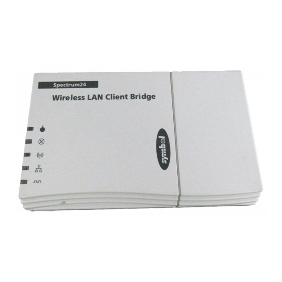
Technical Specifications Technical Specifications Client Bridge Manufacturer/Model Symbol Technologies/CB-1000 Dimensions 6.2 in. x 3.9 in. x 1.0 in. 15.7 cm x 9.9 cm x 2.5 cm Serial Port DB9 female with optional hardware flow control, baud rates 9600 - 115,200 Ethernet Port 10BaseT with straight-through RG-45 Antenna Connector... - Page 39 Index Revision D MobileLink Index-1 2002783-060...
- Page 40 For your notes Index-2 MobileLink Revision D 2002783-060...
- Page 41 Index troubleshooting 27 access points encryption 10 UART (Universal Asynchronous Receiver/Transmitter) pinging 28 antenna diversity 9 ASCII (American Standard Code for Information Interchange) 32 verification 26 BNC (Bayonet Navy Connector) 32 Wi-Fi (Wireless Fidelity) 33 BPSK (Binary Phase Shift Keying) 32 WLAN (Wireless Local Area Network) 33 Configuration Capture file 3, 8, 25 CVSCTRL utility 28...
- Page 42 Index Index-4 MobileLink Revision D 2002783-060...
- Page 44 Asia Headquarters World Headquarters GE Medical Systems GE Medical Systems GE Medical Systems Information Technologies GmbH Information Technologies Asia; GE (China) Co., Ltd. Information Technologies, Inc. Munzinger Straße 3-5 24th Floor, Shanghai MAXDO Center, 8200 West Tower Avenue D-79111 Freiburg...