
Related Manuals for Siemens NXAIR


Summary of Contents for Siemens NXAIR
- Page 1 Medium-Voltage Switchgear Air-Insulated Switchgear NXAIR ≤ 17.5 kV / ≤ 40 kA / ≤ 4000 A Busbar Current OPERATING INSTRUCTIONS Order No.: 110-0134.9 Issue: January 2019 Revision: © Siemens AG 2019. All rights reserved.
- Page 2 For details about technical design and equipment sufficiently by these instructions, the matter should like e. g. technical data, secondary equipment, circuit be referred to the competent Siemens department. diagrams, please refer to the order documents. The contents of this instruction manual shall not...
-
Page 3: Safety Instructions
INFORMATION Provides additional information to clarify or simplify a procedure. Observe the information. Operation symbol: Asks the operator to perform an operation. ✓ Result symbol: Identifies the result of an operation. NXAIR / ≤ 40 kA 110-0134.9 / 14... -
Page 4: Table Of Contents
Closing the high-voltage door ........................42 10.6 High-voltage door with ventilation flap ......................44 10.7 Positions of the withdrawable circuit-breaker / circuit-breaker truck ...............46 10.8 Racking the withdrawable circuit-breaker / circuit-breaker truck to service position ........47 NXAIR / ≤ 40 kA 110-0134.9 / 14... - Page 5 Racking the contactor truck to test position ....................157 14.9 Closing the contactor electrically ......................... 160 14.10 Opening the contactor electrically ........................ 161 14.11 Opening the contactor manually ........................162 14.12 Operating conditions without auxiliary voltage ..................... 164 NXAIR / ≤ 40 kA 110-0134.9 / 14...
- Page 6 Earthing the busbar system manually ......................273 21.2 De-earthing the busbar system manually .....................278 22 Operating the shutters ......................... 283 22.1 Operating the shutter to the busbar compartment in the switching-device compartment ......283 NXAIR / ≤ 40 kA 110-0134.9 / 14...
- Page 7 Preventive maintenance ..........................419 29.5 Lubricants to be used ..........................421 29.6 Overpressure monitors (optional), function test ................... 422 29.7 Maintenance of fan(s) for forced ventilation ....................425 29.8 Switchgear extension ........................... 425 NXAIR / ≤ 40 kA 110-0134.9 / 14...
- Page 8 30.2 Panels with switching-device truck .......................429 30.3 Panels with switch-fuse combination ......................431 31 Index ..............................432 Document information: Title: Operating Instructions Order number: 110-0134.9 Additional order number: 8BX3300-0LA00-0AB1 Revision: Issue: January 2019 NXAIR / ≤ 40 kA 110-0134.9 / 14...
-
Page 9: General Instructions
Siemens, including documentation of the test results. • Maintenance was not done according to the Operating Instructions of the Siemens products. The edition of the standard is only mentioned in the test report applicable at the time of switchgear manufacture. -
Page 10: Personal Protective Equipment (Ppe)
When the switchgear is operated within the technical parameters defined in these instructions, the air- insulated switchgear type NXAIR is suitable for rated voltages up to and Ur ≤ 17.5 kV and a maximum rated short-time withstand current of I = 40 kA. -
Page 11: Update Of The Firmware Of Protection Relays
Update the firmware of the protection relays with the latest firmware version. Siemens protection relays are monitored for their firmware vulnerability. In case that any potential weak points are identified, which might allow third parties to access to the protection relay, information concerning this will be distributed by newsletter. -
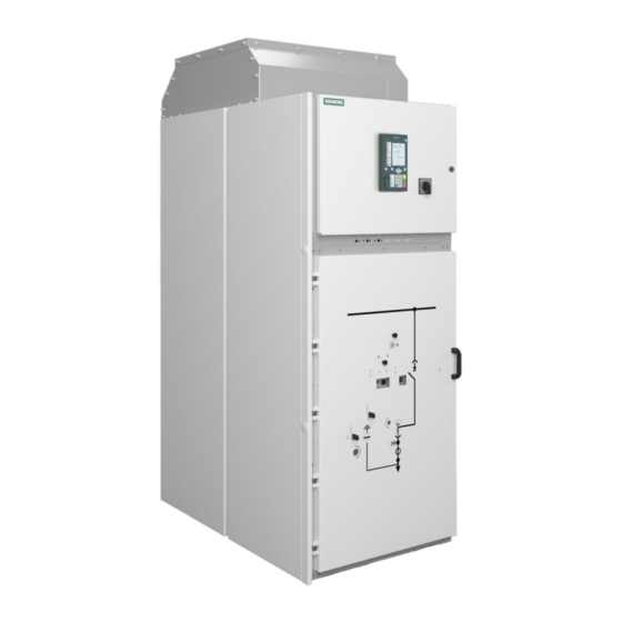
Page 12: Features
Features Features The air-insulated medium-voltage switchgear type NXAIR has the following features: • Factory-assembled, type-tested, metal-enclosed and metal-clad switchgear for indoor installation • Type of accessibility A • Internal arc classification (IAC): IAC A FLR ≤ 40 kA 1 s or IAC A FL ≤ 40 kA 1 s according to IEC 62271 Part 200 •... -
Page 13: Technical Data
Disconnectors / earthing switches 62271-102 Switch-fuse combination 62271-105 Current limiting fuses 60282-1 Voltage detecting systems 61243-5 Insulation 60071-1 Degree of protection 60529 Current transformers 61869-2 Instrument transformers Voltage transformers 61869-3 Installation, erection 61936-1 NXAIR / ≤ 40 kA 110-0134.9 / 14... -
Page 14: Electromagnetic Compatibility - Emc
A: Type of accessibility A; for authorized personnel only The IAC classification is referred to each panel. The data on the rating plate (see fig. 1) describes the areas classified for the corresponding panel. NXAIR / ≤ 40 kA 110-0134.9 / 14... -
Page 15: Panel Dimensions
1000 ─ Metering panel Contactor panel ─ ─ Switch- disconnector panel ─ ─ Contactor panel version with rated voltage 7.2 kV or 12 kV Contactor panel version with rated voltage 7.2 kV NXAIR / ≤ 40 kA 110-0134.9 / 14... - Page 16 1540 or 1650 ≤ 4000 Rear duct version Panel version with rear duct is extended by 600 mm 1400 1500 1500 Contactor panel 1350 1500 1500 Switch- ─ 1350 1500 disconnector panel NXAIR / ≤ 40 kA 110-0134.9 / 14...
-
Page 17: Room Planning
* If NXAIR is used under other service conditions than normal service conditions acc. to IEC 62271 Part 1 regarding the ambient air temperature, the permissible current ratings of feeder and busbar can deviate. In this case please contact the regional Siemens representative to clarify permissible current values. -
Page 18: Operating Instructions For Circuit-Breaker Type 3Ae
For circuit-breakers type 3AE, separate operating instructions are available with detailed instructions and information. The operating instructions are supplied as standard with every circuit-breaker type 3AE. Additional operating instructions in different languages can be ordered at the regional Siemens representative. -
Page 19: Operating Instructions For Contactor Type 3Tl8 And 3Tm3
For contactors type 3TL8 and 3TM3, separate operating instructions are available with detailed instructions and information. The operating instructions are supplied as standard with every contactor type 3TL and 3TM. Additional operating instructions in different languages can be ordered at the regional Siemens representative. -
Page 20: Switch-Fuse Combination Type L-Tri 5F
For switch-fuse combination type L-TRI 5F, separate operating instructions are available with detailed instructions and information. For further information about maintenance and servicing, please refer to the operating instructions indoor switch-fuse combination L-TRI5. Operating instructions can be ordered at the regional Siemens representative. Order number of operating instructions... -
Page 21: Overview Of Panel Types
Overview of panel types Overview of panel types The air-insulated medium-voltage switchgear NXAIR consists of various panel versions which can be freely combined according to the requirements. The following panel types are available: • Circuit-breaker panel • Disconnecting panel •... - Page 22 / metering part / metering truck metering truck Fig. 16: Circuit-breaker panel Fig. 17: Contactor panel Fig. 18: Contactor panel with removable width 600 mm width 435 mm voltage transformers NXAIR / ≤ 40 kA 110-0134.9 / 14...
- Page 23 Fig. 22: Bus sectionalizer type 2 to the right circuit-breaker and bus riser panel with withdrawable metering part / metering truck 1) Can also be designed as a mirror image to the left NXAIR / ≤ 40 kA 110-0134.9 / 14...
- Page 24 Overview of panel types Fig. 23: Panel version with Fig. 24: Panel version with natural ventilation natural ventilation NXAIR / ≤ 40 kA 110-0134.9 / 14...
-
Page 25: Panel Design
Panel design Basic design In the basic design, NXAIR is available both as withdrawable and as truck-type switchgear. In the basic design as withdrawable switchgear, the removable part is taken out of the panel or inserted in the panel by means of a service truck. -
Page 26: Basic Design Circuit-Breaker Panel
Fig. 27: Sectional view of circuit-breaker panel design Basic design circuit-breaker panel with forced ventilation Switching-device compartment Busbar compartment Connection compartment Withdrawable circuit-breaker Low-voltage compartment (1) Fan box Fig. 28: Sectional view of circuit-breaker panel design with forced ventilation NXAIR / ≤ 40 kA 110-0134.9 / 14... -
Page 27: Basic Design Contactor Panel With Panel Width 435 Mm
(6) Feeder earthing switch (7) Cable / bar connection (8) Block-type current transformers (9) Bushing-type insulators (10) Busbar (11) Pressure relief duct Fig. 30: Sectional view of contactor panel with panel width 600 mm NXAIR / ≤ 40 kA 110-0134.9 / 14... -
Page 28: Basic Design Switch-Disconnector Panel
(6) HV HRC fuse-links (7) Blades of the switch-fuse combination (8) Busbars Fig. 31: Sectional view of switch-disconnector panel Further information to design features and design options is given in catalog HA 25.71. NXAIR / ≤ 40 kA 110-0134.9 / 14... -
Page 29: Interlocks
Opening the high-voltage door Withdrawable part in test position Closing the high-voltage door Low-voltage connector plugged on INFORMATION Contactor panels with panel width 435 mm and 600 width mm are not available for withdrawable switchgear. NXAIR / ≤ 40 kA 110-0134.9 / 14... -
Page 30: Mechanical Interlocks In Panel Versions With Switching-Device Trucks
Feeder earthing switch in OPEN position and high- Operating the switch-fuse combination voltage door closed Switch-fuse combination in OPEN position and Operating the feeder earthing switch high-voltage door closed Opening the high-voltage door Switch-fuse combination in OPEN position NXAIR / ≤ 40 kA 110-0134.9 / 14... -
Page 31: Additional Electromagnetic Interlocks (Optional)
Operating the feeder earthing switch removing the padlock Access to actuating openings only after Operating the busbar earthing switch removing the padlock Access to actuating openings only after Opening the high-voltage door removing the padlock NXAIR / ≤ 40 kA 110-0134.9 / 14... -
Page 32: Additional Key-Operated Interlock (Optional)
Switching the busbar earthing switch to Access to actuating openings only after CLOSED position opening the lock Switching the busbar earthing switch to Access to actuating openings only after OPEN position opening the lock NXAIR / ≤ 40 kA 110-0134.9 / 14... -
Page 33: Accessories
/ panel operating the switch-fuse combination Fig. 36: Hand crank for manual charging of the spring energy store in the circuit-breaker NXAIR / ≤ 40 kA 110-0134.9 / 14... - Page 34 Fig. 40: Slip-on levers for opening the shutters (optional) (1) for use on left side in panel and (2) for use in right side in panel Fig. 41: Wall-mounting holder for storage of operating tools (optional) NXAIR / ≤ 40 kA 110-0134.9 / 14...
-
Page 35: Service Truck
Transporting other objects than the corresponding withdrawable part Service truck versions Depending on the panel version, the following service trucks are included as accessories: For panels with withdrawable circuit-breaker, withdrawable disconnector link or withdrawable metering part: NXAIR / ≤ 40 kA 110-0134.9 / 14... - Page 36 Fig. 43: Service truck to insert and remove a withdrawable part On the right side of the service truck there is the pocket for the operating instructions: Fig. 44: Front page of operating instructions NXAIR / ≤ 40 kA 110-0134.9 / 14...
- Page 37 Accessories Fig. 45: Rear page of operating instructions For panels with removable voltage transformers: Operating side Rear side Fig. 46: Service truck to insert and remove the removable voltage transformers NXAIR / ≤ 40 kA 110-0134.9 / 14...
-
Page 38: Customer Support
For further support, contact the Siemens after-sales service. Repairs Repairs are carried out by fully trained Siemens technicians, who arrive equipped with original spare parts for the switchgear. Before you call To help us deal with your query more quickly, make sure that the following information is at hand: •... -
Page 39: Operating The Circuit-Breaker Panel
(19) Actuating opening for opening the circuit-breaker Fig. 48: Control elements on the panel front of the circuit-breaker panel (20) Actuating opening for closing the circuit-breaker Rotary button to close and open the actuating opening (21) located below NXAIR / ≤ 40 kA 110-0134.9 / 13... -
Page 40: Position Indicators Visible On High-Voltage Door
CLOSED position or OPEN position 10.3 Access to compartments Regarding accessibility to the individual compartments, NXAIR switchgear fulfills the loss of service continuity category LSC 2B according to IEC 62271-200. The degree of protection between the individual compartments is IP2X in standard design. -
Page 41: Opening The High-Voltage Door
19. Preconditions • Withdrawable circuit-breaker / circuit-breaker truck in test position • Spring energy store in the circuit-breaker discharged • High-voltage door closed • Padlock (optional) removed from door handle NXAIR / ≤ 40 kA 110-0134.9 / 14... -
Page 42: Closing The High-Voltage Door
Before leaving the panel front. CAUTION Injury The mechanism inside the withdrawable circuit-breaker / circuit-breaker truck can cause injuries by getting squeezed, caught or cut. Do not remove any parts of the covering. NXAIR / ≤ 40 kA 110-0134.9 / 14... - Page 43 Push the door handle on the high-voltage door totally upwards, and hold it. Press the high-voltage door totally onto the panel frame using the door handle. Push the door handle on the high-voltage door totally downwards, and release it. NXAIR / ≤ 40 kA 110-0134.9 / 14...
-
Page 44: High-Voltage Door With Ventilation Flap
Reading the position indicator Read the position indicator for the ventilation flap in the high-voltage door: Fig. 53: Ventilation flap not in operational Fig. 52: Ventilation flap in operational position, negative indication position, positive indication NXAIR / ≤ 40 kA 110-0134.9 / 14... - Page 45 Fig. 54: Inside view of high-voltage door Now the mechanism holds the ventilation flap in this position by itself. Close the high-voltage door. ✓ The ventilation flap in the high-voltage door is in operational position. NXAIR / ≤ 40 kA 110-0134.9 / 14...
-
Page 46: Positions Of The Withdrawable Circuit-Breaker / Circuit-Breaker Truck
Step 3 Step 2 Insert and turn double-bit key Turn and remove double-bit key Insert and turn racking crank as far as it will go from from and pull it off 90° 90° NXAIR / ≤ 40 kA 110-0134.9 / 14... -
Page 47: Racking The Withdrawable Circuit-Breaker / Circuit-Breaker Truck To Service Position
Padlock (optional) removed from operating slide • For electromagnetic interlock (optional): • Electromagnetic interlock deactivated • For panels with removable voltage transformers (optional): • Door to voltage transformer compartment closed and screwed tight NXAIR / ≤ 40 kA 110-0134.9 / 14... - Page 48 To release access to the withdrawable circuit-breaker / circuit-breaker truck, insert the double-bit key and turn clockwise as far as it will go (that is 90°). Fig. 60: Lifting the operating slide Fig. 61: Turning the double-bit key clockwise NXAIR / ≤ 40 kA 110-0134.9 / 14...
- Page 49 Fig. 64: Position indicator in service position ✓ The withdrawable circuit-breaker / circuit-breaker truck has been racked from test position to service position; the position indicator is in service position (vertical bar). NXAIR / ≤ 40 kA 110-0134.9 / 14...
-
Page 50: Racking The Withdrawable Circuit-Breaker / Circuit-Breaker Truck To Test Position
The actuating opening for racking the withdrawable circuit-breaker / circuit-breaker truck is located on the control board of the high-voltage door. Fig. 67: Actuating opening for racking the Fig. 68: Racking crank Fig. 69: Double-bit key, withdrawable circuit-breaker / diameter 5 mm circuit-breaker truck NXAIR / ≤ 40 kA 110-0134.9 / 14... - Page 51 Push the racking crank for moving the withdrawable circuit-breaker / circuit-breaker truck onto the operating shaft, and turn counter-clockwise as far as it will go. Remove the racking crank for moving the withdrawable circuit-breaker / circuit-breaker truck. NXAIR / ≤ 40 kA 110-0134.9 / 14...
- Page 52 Fig. 74: Position indicator in test position ✓ The withdrawable circuit-breaker / circuit-breaker truck has been racked from service position to test position; the position indicator is in test position (horizontal bar). NXAIR / ≤ 40 kA 110-0134.9 / 14...
-
Page 53: Closing The Circuit-Breaker Electrically
After closing, the closing spring is immediately automatically charged by the motor and the spring state indicator changes to CHARGED. Change of the spring state indicator during closing operation: Charged Discharged Charged NXAIR / ≤ 40 kA 110-0134.9 / 14... -
Page 54: Opening The Circuit-Breaker Electrically
Operating the circuit-breaker discharges and/or charges the spring energy store abruptly. This causes a short loud noise and low vibration. Expect switching noise and low vibration from inside the circuit-breaker. INFORMATION The opening spring is charged during the closing operation. NXAIR / ≤ 40 kA 110-0134.9 / 14... -
Page 55: Closing The Circuit-Breaker Manually
Connect the auxiliary voltage before closing the circuit-breaker manually. Otherwise the spring energy store must be recharged manually with a hand crank. NXAIR / ≤ 40 kA 110-0134.9 / 14... - Page 56 Padlock (optional) removed from actuating opening • Push rod available Fig. 77: High-voltage door with actuating opening Fig. 78: Push rod Procedure Turn cover of actuating opening aside using the rotary button located over it. NXAIR / ≤ 40 kA 110-0134.9 / 14...
- Page 57 Fit a padlock (optional) to the actuating opening and close it. ✓ The position indicator on the circuit-breaker changes from 0 position to I position. The operations counter is increased by 1. The circuit-breaker is closed. NXAIR / ≤ 40 kA 110-0134.9 / 14...
-
Page 58: Opening The Circuit-Breaker Manually
• High-voltage door closed • Panel set to local control • Padlock (optional) removed from actuating opening • Push rod available Fig. 82: High-voltage door with actuating opening Fig. 83: Push rod NXAIR / ≤ 40 kA 110-0134.9 / 14... - Page 59 Take the push rod out of the actuating opening. Fit a padlock (optional) to the actuating opening and close it. ✓ The position indicator on the circuit-breaker changes from I position to 0 position. The circuit-breaker is open. NXAIR / ≤ 40 kA 110-0134.9 / 14...
-
Page 60: Discharging The Spring Energy Store
The operating sequence is OPEN-CLOSE-OPEN manually. Open the circuit-breaker manually by using the push rod. Close the circuit-breaker manually by using the push rod. Change of the spring state indicator during closing operation: Charged Discharged NXAIR / ≤ 40 kA 110-0134.9 / 14... -
Page 61: Charging The Spring Energy Store Manually
Remove the hand crank from the actuating opening immediately after manual charging of the spring energy store. Never leave the hand crank in the actuating opening. NXAIR / ≤ 40 kA 110-0134.9 / 14... - Page 62 Auxiliary voltage for the panel disconnected • Hand crank available Fig. 89: Actuating opening on Fig. 90: Hand crank for manual charging of the high-voltage door spring energy store in the circuit-breaker NXAIR / ≤ 40 kA 110-0134.9 / 14...
- Page 63 Close the access cover of operating shaft using the rotary button. ✓ Manual charging of the spring energy store is completed. The energy required for the operating sequence (OPEN-)CLOSE-OPEN is stored in the spring energy store. NXAIR / ≤ 40 kA 110-0134.9 / 14...
-
Page 64: Earthing The Feeder Manually
Feeder to be earthed is isolated • Withdrawable circuit-breaker / circuit-breaker truck in test position • Operating lever available • Padlock (optional) removed from operating slide • For electromagnetic interlock (optional): • Electromagnetic interlock deactivated NXAIR / ≤ 40 kA 110-0134.9 / 14... - Page 65 While keeping the operating slide lifted, insert the operating lever slightly into the actuating opening such that the pins in the operating lever are horizontal. Insert the operating lever into the actuating opening as far as it will go. Fig. 97: Inserting the operating lever NXAIR / ≤ 40 kA 110-0134.9 / 14...
-
Page 66: Earthing The Feeder Manually
Do not try to remove the operating lever at intermediate positions. NOTICE Maloperation If the operating lever is not inserted correctly, the feeder earthing switch may be damaged. Insert the operating lever in the actuating opening as far as it will go. NXAIR / ≤ 40 kA 110-0134.9 / 14... - Page 67 Padlock (optional) removed from operating slide • For electromagnetic interlock (optional): • Electromagnetic interlock deactivated Fig. 101: Actuating opening on high-voltage door Fig. 102: Operating lever for operating the feeder earthing switch NXAIR / ≤ 40 kA 110-0134.9 / 14...
- Page 68 180° until the feeder earthing switch changes to OPEN position. Fig. 105: Turning operating lever Fig. 106: Position indicator on the high-voltage counter-clockwise door in OPEN position Remove the operating lever. NXAIR / ≤ 40 kA 110-0134.9 / 14...
-
Page 69: Removing The Low-Voltage Connector
Remove the low-voltage connector (2) carefully to the front. Fig. 107: Removing the low-voltage connector Hang the low-voltage connector into the support located underneath the low-voltage compartment. Fig. 108: Low-voltage connector stowed away NXAIR / ≤ 40 kA 110-0134.9 / 14... -
Page 70: Plugging On The Low-Voltage Connector
/ circuit-breaker truck informs about plugging on the low-voltage connector. Follow the advice on the label (3) to push the longitudinal fastener. Fig. 109: Instruction label on the withdrawable circuit-breaker / circuit-breaker truck NXAIR / ≤ 40 kA 110-0134.9 / 14... - Page 71 The motor in the circuit-breaker starts up and charges the spring energy store. The spring state indicator for the closing spring changes to CHARGED. ✓ The low-voltage connector is plugged on and secured by the longitudinal fastener. NXAIR / ≤ 40 kA 110-0134.9 / 14...
-
Page 72: Taking The Withdrawable Circuit-Breaker Out Of The Panel
Service truck available and selected according to the corresponding panel width • Withdrawable circuit-breaker in test position • Spring energy store in the circuit-breaker discharged • High-voltage door open • Low-voltage connector stowed away NXAIR / ≤ 40 kA 110-0134.9 / 14... - Page 73 Observe that the guide rails of the panel and the service truck are horizontally aligned with each other. Fig. 115: Service truck in front of panel NXAIR / ≤ 40 kA 110-0134.9 / 14...
- Page 74 Unlocking the withdrawable circuit-breaker from the panel To unlock the withdrawable circuit-breaker from the panel frame, turn the two locking levers at the withdrawable circuit-breaker to the outside. Fig. 118: Unlocking the withdrawable circuit-breaker NXAIR / ≤ 40 kA 110-0134.9 / 14...
- Page 75 Fig. 121: Interlocking the withdrawable circuit-breaker Pull the two unlocking levers on the left and right side of the service truck upwards to release the interlocking with the panel frame. Fig. 122: Unlocking the service truck NXAIR / ≤ 40 kA 110-0134.9 / 14...
- Page 76 Fig. 124: Moving the service truck with circuit-breaker type 3AE1 circuit-breaker type 3AE5 If no further operation is executed: Close the high-voltage door. ✓ The withdrawable circuit-breaker can now be moved outside the panel on the service truck. NXAIR / ≤ 40 kA 110-0134.9 / 14...
-
Page 77: Inserting The Withdrawable Circuit-Breaker In A Panel
Risk of damaging safety-relevant parts. Operating the switchgear with a withdrawable part version that is not suitable for the corresponding panel version can cause serious damage to the switchgear. Do not change the mechanical coding or the coding symbols. NXAIR / ≤ 40 kA 110-0134.9 / 14... - Page 78 Circuit-breaker panels with extended control functions are equipped with a second release (a second shunt release / a c.t.-release / an undervoltage release). Extended control functions are coded by a combination of two symbols. NXAIR / ≤ 40 kA 110-0134.9 / 14...
- Page 79 Carefully compare the coding symbols on the top side of the withdrawable part (1) with the symbols on the top side of the low-voltage connector (2). Fig. 127: Verifying correspondence of coding symbols on withdrawable part and low-voltage connector (example) NXAIR / ≤ 40 kA 110-0134.9 / 14...
- Page 80 Make sure the service truck is interlocked with the panel before moving the withdrawable circuit-breaker into the panel. Observe the notes and the operating instructions on the service truck. NXAIR / ≤ 40 kA 110-0134.9 / 14...
- Page 81 Observe that the guide rails of the panel and the service truck are horizontally aligned with each other. Fig. 131: Service truck in front of panel NXAIR / ≤ 40 kA 110-0134.9 / 14...
- Page 82 To release the interlocking of the withdrawable circuit-breaker with the service truck, turn the two locking levers at the withdrawable circuit-breaker to the outside. Fig. 134: Releasing the interlocking of the withdrawable circuit-breaker NXAIR / ≤ 40 kA 110-0134.9 / 14...
- Page 83 Unlocking the service truck from the panel Pull the two unlocking levers on the left and right side of the service truck upwards to release the interlocking with the panel frame. Fig. 137: Unlocking the service truck NXAIR / ≤ 40 kA 110-0134.9 / 14...
- Page 84 In addition to these instructions, an instruction label on the withdrawable circuit- breaker informs about plugging on the low-voltage connector. Follow the advice on the label (3) to push the longitudinal fastener. Fig. 140: Instruction label on the withdrawable circuit-breaker NXAIR / ≤ 40 kA 110-0134.9 / 14...
- Page 85 The motor in the circuit-breaker starts up and charges the spring energy store. The spring state indicator for the closing spring changes to CHARGED. ✓ The withdrawable circuit-breaker is inserted in the panel and the high-voltage door is closed. NXAIR / ≤ 40 kA 110-0134.9 / 14...
-
Page 86: Taking The Circuit-Breaker Truck Out Of The Panel
Fig. 144: Circuit-breaker panel with high-voltage door open Preconditions • Circuit-breaker truck in test position • Spring energy store in the circuit-breaker discharged • High-voltage door open • Low-voltage connector stowed away NXAIR / ≤ 40 kA 110-0134.9 / 14... - Page 87 Remove objects such as small parts, installation material or tools from the floor in the travel area. Move the circuit-breaker truck only slowly and constantly. The circuit-breaker truck is not suitable for unsteady floor, such as stairs, deepening or floor joints. NXAIR / ≤ 40 kA 110-0134.9 / 14...
- Page 88 Pull the circuit-breaker truck out of the panel using the handles. Fig. 148: Pulling out the circuit-breaker truck If no further operation is executed: Close the high-voltage door. ✓ The circuit-breaker truck can now be moved away from the panel. NXAIR / ≤ 40 kA 110-0134.9 / 14...
-
Page 89: Inserting The Circuit-Breaker Truck In A Panel
Risk of damaging safety-relevant parts. Operating the switchgear with a circuit- breaker truck version that is not suitable for the corresponding panel version can cause serious damage to the switchgear. Do not change the mechanical coding or the coding symbols. NXAIR / ≤ 40 kA 110-0134.9 / 14... - Page 90 (circuit-breaker panels: also for control functions) Optional: Coding symbol for current rating (circuit-breaker panels: also for control functions) Top side of low-voltage connector Fig. 150: Coding symbols on low-voltage connector and switching-device truck NXAIR / ≤ 40 kA 110-0134.9 / 14...
- Page 91 Other than Rated current circuit-breaker Examples: symbol Circuit-breaker Rated current and (5; optional) extended control functions For single use of symbols or for use in combinations of symbols Other than Rated current circuit-breaker NXAIR / ≤ 40 kA 110-0134.9 / 14...
- Page 92 Fig. 152: Coupling pin of the operating shaft for Fig. 153: Coupling of the feeder the feeder earthing switch earthing switch in the switching-device compartment NXAIR / ≤ 40 kA 110-0134.9 / 14...
- Page 93 Do not push the locking bracket downwards towards LOCK if • the circuit-breaker truck is outside the panel. • the circuit-breaker truck is moved only partially into the panel. NXAIR / ≤ 40 kA 110-0134.9 / 14...
- Page 94 (2) at the bottom of the panel. Push the circuit-breaker truck into the panel as far as it will go. Fig. 156: Circuit-breaker truck in front of panel NXAIR / ≤ 40 kA 110-0134.9 / 14...
- Page 95 To interlock the circuit-breaker truck with the panel frame at the center, turn the two locking levers to the inside. The circuit-breaker truck is correctly interlocked with the panel as soon as both locking levers latch tight inside. Fig. 159: Interlocking circuit-breaker truck at the center NXAIR / ≤ 40 kA 110-0134.9 / 14...
- Page 96 Carefully plug on the low-voltage connector (2) from the front. To secure the low-voltage connector, push the longitudinal fastener (1) of the coupling downwards. Fig. 163: Plugging on and securing the low-voltage connector NXAIR / ≤ 40 kA 110-0134.9 / 14...
- Page 97 The motor in the circuit-breaker starts up and charges the spring energy store. The spring state indicator for the closing spring changes to CHARGED. ✓ The circuit-breaker truck is inserted in the panel and the high-voltage door is closed. NXAIR / ≤ 40 kA 110-0134.9 / 14...
-
Page 98: Operating The Disconnecting Panel
11.2 Position indicators visible on high-voltage door Withdrawable disconnector link / Service position Intermediate position Test position disconnector truck: Service position, intermediate position or test position Feeder earthing switch: CLOSED OPEN CLOSED position or OPEN position ─ NXAIR / ≤ 40 kA 110-0134.9 / 13... -
Page 99: Access To Compartments
Operating the disconnecting panel 11.3 Access to compartments Regarding accessibility to the individual compartments, NXAIR switchgear fulfills the loss of service continuity category LSC 2B according to IEC 62271-200. The degree of protection between the individual compartments is IP2X. The type of accessibility is provided as follows:... - Page 100 / circuit-breaker truck to service position and/or test position. For racking the withdrawable disconnector link / disconnector truck to service position and/or test position, see chapter 10.8 and/or 10.9. NXAIR / ≤ 40 kA 110-0134.9 / 14...
-
Page 101: Removing Or Plugging On The Low-Voltage Connector
11.9 Design of the withdrawable disconnector link / disconnector truck (1) Handle for pulling (2) Contact arm assembly with tulip contact (3) Racking mechanism Fig. 165: Design of the withdrawable disconnector link / disconnector truck (example) NXAIR / ≤ 40 kA 110-0134.9 / 14... -
Page 102: Operating The Metering Panel
Fig. 166: Control elements on the panel front 12.2 Position indicator visible on high-voltage door Indicator for position of withdrawable metering part / metering truck: Service position Intermediate position Test position Position indications for: NXAIR / ≤ 40 kA 110-0134.9 / 13... -
Page 103: Access To Compartments
Operating the metering panel 12.3 Access to compartments Regarding accessibility to the individual compartments, NXAIR switchgear fulfills the loss of service continuity category LSC 2B according to IEC 62271-200. The degree of protection between the individual compartments is IP2X. The type of accessibility is provided as follows:... -
Page 104: Taking The Withdrawable Metering Part / Metering Truck Out Of The Panel Or Inserting In A Panel
Withdrawable metering parts / metering trucks are exclusively designed for operation with specific protection fuse-links. Use only the fuse-link types listed in the following table. Do not mount bridging links instead of protection fuse-links. NXAIR / ≤ 40 kA 110-0134.9 / 14... - Page 105 • Set of proper protection fuse-links available Replacing protection fuse-links for rated voltage ≤ 12 kV Removable protection fuse-link Fixed-mounted voltage transformer Fig. 170: Withdrawable metering part, taken out of the panel NXAIR / ≤ 40 kA 110-0134.9 / 14...
- Page 106 INFORMATION Final procedure steps Next, insert the withdrawable metering part / metering truck into the panel. After closing the high-voltage door, the panel can be integrated into the course of operation again. NXAIR / ≤ 40 kA 110-0134.9 / 14...
- Page 107 Pull the upper end of the protection fuse-link off the clamp and remove the protection fuse-link. Fig. 173: Insulating cover Fig. 174: Use of a Fig. 175: Pulling off the removed screwdriver fuse-link NXAIR / ≤ 40 kA 110-0134.9 / 14...
- Page 108 INFORMATION Final procedure steps Next, insert the withdrawable metering part / metering truck into the panel. After closing the high-voltage door, the panel can be integrated into the course of operation again. NXAIR / ≤ 40 kA 110-0134.9 / 14...
-
Page 109: Operating The Contactor Panel With Panel Width 435 Mm
Actuating opening for inserting the double-bit (12) key to control racking the contactor truck Actuating opening manual emergency (13) opening of the contactor Fig. 179: Control elements on the panel front NXAIR / ≤ 40 kA 110-0134.9 / 12... -
Page 110: Position Indicator Visible On High-Voltage Door
Position indications for: 13.3 Access to compartments Regarding accessibility to the individual compartments, NXAIR switchgear fulfills the loss of service continuity category LSC 2B according to IEC 62271-200. The degree of protection between the individual compartments is IP2X in standard design. -
Page 111: Closing The High-Voltage Door
Close the high-voltage door: If an activity inside the switching-device compartment is interrupted. Immediately after an activity inside the switching-device compartment was completed. Before leaving the panel front. NXAIR / ≤ 40 kA 110-0134.9 / 14... - Page 112 Press the high-voltage door totally onto the panel frame using the door handle. Push the door handle on the high-voltage door totally downwards and release it. Fig. 182: Closing the high-voltage door NXAIR / ≤ 40 kA 110-0134.9 / 14...
-
Page 113: Positions Of The Contactor Truck
Step 3 Step 2 Insert and turn double-bit key Turn and remove double-bit key Insert and turn racking crank as far as it will go from from and pull it off 90° 90° NXAIR / ≤ 40 kA 110-0134.9 / 14... -
Page 114: Racking The Contactor Truck To Service Position
Fig. 184: Double-bit key with a diameter of 5 mm Procedure NOTICE Maloperation All interlocks are only released when the contactor truck is in a stable end position. Rack the contactor truck absolutely until end position. NXAIR / ≤ 40 kA 110-0134.9 / 14... - Page 115 To close the actuating opening, push the operating slide down as far as it will go. Fit a padlock (optional) to the operating slide and close it. ✓ The contactor truck has been racked from test position to service position. NXAIR / ≤ 40 kA 110-0134.9 / 14...
-
Page 116: Racking The Contactor Truck To Test Position
Fig. 191: Double-bit key with a diameter of 5 mm Procedure NOTICE Maloperation All interlocks are only released when the contactor truck is in a stable end position. Rack the contactor truck absolutely until end position. NXAIR / ≤ 40 kA 110-0134.9 / 14... - Page 117 To close the actuating opening, push the operating slide down as far as it will go. Fit a padlock (optional) to the operating slide and close it. ✓ The contactor truck has been racked from service position to test position. NXAIR / ≤ 40 kA 110-0134.9 / 14...
-
Page 118: Closing The Contactor Electrically
(for example by switching the local-remote switch). INFORMATION Unexpected switching noise and vibration Operating the contactor causes a short loud noise and low vibration. Expect switching noise and low vibration from inside the contactor. NXAIR / ≤ 40 kA 110-0134.9 / 14... -
Page 119: Opening The Contactor Manually
Manual operation of the contactor is limited to manual opening of the contactor. Manual closing of the contactor is not possible. INFORMATION Contactor truck version with mechanical closing latch Opening the contactor also opens the closing latch. NXAIR / ≤ 40 kA 110-0134.9 / 14... - Page 120 You may now go on to insert the crank for racking the contactor truck. Otherwise remove the double-bit key, push the operating slide down, fit a padlock (optional) to the operating slide and close it. NXAIR / ≤ 40 kA 110-0134.9 / 14...
-
Page 121: Manual Emergency Opening Of The Contactor
Insert the push rod through the actuating opening in the high-voltage door and press it to the frame as far as it will go. Fig. 199: High-voltage door with Fig. 200: Push rod inserted actuating opening ✓ The contactor is open. NXAIR / ≤ 40 kA 110-0134.9 / 14... -
Page 122: Operating Conditions Without Auxiliary Voltage
If the contactor is in CLOSED position before starting the procedure, turning the double-bit key 90° opens the contactor. This causes a short loud noise and low vibration. Expect switching noise and low vibration from inside the contactor when turning the double-bit key. NXAIR / ≤ 40 kA 110-0134.9 / 14... - Page 123 To release the actuating opening for the double-bit key, lift the operating slide and hold it. Fig. 203: Lifting the operating slide Insert the double-bit key without turning. Fig. 204: Double-bit key inserted NXAIR / ≤ 40 kA 110-0134.9 / 14...
- Page 124 Push the racking crank for moving the contactor truck onto the operating shaft, and turn counter-clockwise as far as it will go. Remove the racking crank for moving the contactor truck. NXAIR / ≤ 40 kA 110-0134.9 / 14...
-
Page 125: Earthing The Feeder Manually
Do not try to remove the operating lever at intermediate positions. NOTICE Maloperation If the operating lever is not inserted correctly, the feeder earthing switch may be damaged. Insert the operating lever in the actuating opening as far as it will go. NXAIR / ≤ 40 kA 110-0134.9 / 14... - Page 126 Insert the operating lever in the actuating opening as far as it will go. Turn the operating lever clockwise 180° until the feeder earthing switch changes to CLOSED position. Fig. 213: Lifting the operating slide Fig. 214: Inserting the operating lever NXAIR / ≤ 40 kA 110-0134.9 / 14...
-
Page 127: Earthing The Feeder Manually
Do not try to remove the operating lever at intermediate positions. NOTICE Maloperation If the operating lever is not inserted correctly, the feeder earthing switch may be damaged. Insert the operating lever in the actuating opening as far as it will go. NXAIR / ≤ 40 kA 110-0134.9 / 14... - Page 128 Insert the operating lever in the actuating opening as far as it will go. Turn the operating lever counter-clockwise 180° until the feeder earthing switch changes to OPEN position. Fig. 219: Lifting the operating slide Fig. 220: Inserting the operating lever NXAIR / ≤ 40 kA 110-0134.9 / 14...
-
Page 129: Taking The Contactor Truck Out Of The Panel
CAUTION Injury The mechanism inside the contactor truck can cause injuries by getting squeezed, caught or cut. Do not remove any parts of the covering. NXAIR / ≤ 40 kA 110-0134.9 / 14... - Page 130 Protruding parts Protruding parts such as locking elements at the contactor truck or at the rear of the contactor truck can cause injuries. Move the contactor truck only at the front side. NXAIR / ≤ 40 kA 110-0134.9 / 14...
- Page 131 Release the interlocking with the panel by turning the two locking levers at the contactor truck to the outside. Fig. 227: Releasing the interlocking Fig. 228: Contactor truck unlocked with the panel NXAIR / ≤ 40 kA 110-0134.9 / 14...
- Page 132 Move and operate the contactor truck only at the front side. To move the contactor truck outside of the panel, use two handles. Fig. 229: Handle on contactor truck Fig. 230: Moving the contactor truck using two handles NXAIR / ≤ 40 kA 110-0134.9 / 14...
-
Page 133: Inserting The Contactor Truck In A Panel
Protruding parts such as locking elements at the contactor truck or at the rear of the contactor truck can cause injuries. Move and operate the contactor truck only at the front side. NXAIR / ≤ 40 kA 110-0134.9 / 14... - Page 134 Step on the bottom side of the truck to stabilize the contactor truck during replacement of HV HRC fuse-links Fig. 234: Contactor panel Fig. 233: Contactor truck with high-voltage Ramps door open NXAIR / ≤ 40 kA 110-0134.9 / 14...
- Page 135 Fig. 237: Instruction label on the front side of the contactor truck First, check if the panel requires a contactor truck with/without mechanical closing latch to be inserted. Second, check the front side of the contactor truck for the corresponding instruction label. NXAIR / ≤ 40 kA 110-0134.9 / 14...
- Page 136 (2) at the bottom of the panel. Fig. 238: Positioning the contactor truck in front of the panel If required, support the contactor truck with the handle (3) to move it onto the ramps. NXAIR / ≤ 40 kA 110-0134.9 / 14...
- Page 137 Fig. 240: Pushing the contactor truck at Fig. 241: Lifting the ramps the top into the panel Check whether the contactor truck is correctly placed into the panel by pulling it backwards. NXAIR / ≤ 40 kA 110-0134.9 / 14...
-
Page 138: Replacing Hv Hrc Fuse-Links
After tripping, the surfaces of HV HRC fuse-links are hot. Touching hot HV HRC fuse-links may cause burns. Put on personal protective equipment. Let hot HV HRC fuse-links cool down before replacing. NXAIR / ≤ 40 kA 110-0134.9 / 14... - Page 139 Outer phase L3 with double fuse-link arrangement Middle phase L2 with double fuse-link arrangement Front side of the contactor truck Fig. 245: Seen from top: Arrangement of HV HRC fuse-links (example with double fuse-link arrangement) NXAIR / ≤ 40 kA 110-0134.9 / 14...
- Page 140 (SIBA) (Inter-teknik) [kV] phase +S68T.12KV.442.050.08 3010153.50 3010153.63 +S68T.12KV.442.063.08 +S68T.12KV.442.080.08 3010253.80 3010253.100 +S4T.12KV.442.100.08 3010253.125 +S4T.12KV.442.125.08 1 or 2 1 or 2 3010353.160 +S4T.12KV.442.160.08 Supplier information : www.siba-fuses.com Supplier information : www.inter-teknik.com NXAIR / ≤ 40 kA 110-0134.9 / 14...
- Page 141 Contactor truck taken out of the panel • High-voltage door closed Procedure Step on the bottom side of the truck to stabilize the contactor truck during the replacement of HV HRC fuse-links. NXAIR / ≤ 40 kA 110-0134.9 / 14...
- Page 142 Fig. 248: Opening the fuse-link bracket Fig. 247: Opening the fuse-link bracket in on the opposite side of the the striker area (operating side of striker area (contact tulip side of contactor truck) contactor truck) NXAIR / ≤ 40 kA 110-0134.9 / 14...
- Page 143 If only one HV HRC fuse-link is to be installed in the phase, use the upper position at the clamps. Fig. 252: Inserting the HV HRC fuse-link Fig. 251: Inserting the HV HRC fuse-link on the opposite side of the in the striker area striker area NXAIR / ≤ 40 kA 110-0134.9 / 14...
- Page 144 Fig. 255: Opening the fuse-link bracket in Fig. 256: Opening the fuse-link bracket on the striker area (operating side of the opposite side of striker area contactor truck) (contact tulip side of contactor truck) NXAIR / ≤ 40 kA 110-0134.9 / 14...
- Page 145 Fig. 260: HV HRC fuse-link inserted and fuse -link bracket closed in the fuse-link bracket closed on the striker area opposite side of striker area ✓ The HV HRC fuse-links have been replaced. NXAIR / ≤ 40 kA 110-0134.9 / 14...
-
Page 146: Motor Starting Currents
If this is not feasible, it must be ensured that overload currents that are smaller than the minimum breaking current of the HV HRC fuse-link are interrupted by the switching-device via the striker. This prevents thermal overloading of the HV HRC fuse-link, which would otherwise be destroyed. NXAIR / ≤ 40 kA 110-0134.9 / 14... - Page 147 HV HRC fuse-link. This stress must neither operate nor pre-damage the fuse-link. • Other factors of influence on the stress of the HV HRC fuse-links are the starting time and the starting frequency of the motors. NXAIR / ≤ 40 kA 110-0134.9 / 14...
-
Page 148: Operating The Contactor Panel With Panel Width 600 Mm
(14) actuating opening for operating the feeder earthing switch (15) CLOSED/OPEN indicator of the contactor Fig. 262: Control elements on the panel front Indicator for operation state of (16) HV HRC fuse-links NXAIR / ≤ 40 kA 110-0134.9 / 13... -
Page 149: Position Indicators Visible On High-Voltage Door
CLOSED position or OPEN position 14.3 Access to compartments Regarding accessibility to the individual compartments, NXAIR switchgear fulfills the loss of service continuity category LSC 2B according to IEC 62271-200. The degree of protection between the individual compartments is IP2X in standard design. -
Page 150: Opening The High-Voltage Door
High-voltage door closed • Padlock (optional) removed from door handle Procedure Pull door handle upwards and open the high-voltage door. Fig. 263: Opening the high-voltage door ✓ The high-voltage door is open. NXAIR / ≤ 40 kA 110-0134.9 / 14... -
Page 151: Closing The High-Voltage Door
Padlock for door handle (optional) available Procedure Push the door handle on the high-voltage door totally upwards, and hold it. Press the high-voltage door totally onto the panel frame using the door handle. NXAIR / ≤ 40 kA 110-0134.9 / 14... - Page 152 Push the door handle on the high-voltage door totally downwards and release it. Fig. 265: Closing the high-voltage door Fit a padlock (optional) to the door handle and close it. ✓ The high-voltage door is closed. NXAIR / ≤ 40 kA 110-0134.9 / 14...
-
Page 153: Positions Of The Contactor Truck
Step 3 Step 2 Insert and turn double-bit key Turn and remove double-bit key Insert and turn racking crank as far as it will go from from and pull it off 90° 90° NXAIR / ≤ 40 kA 110-0134.9 / 14... -
Page 154: Racking The Contactor Truck To Service Position
Fig. 267: Double-bit key with a diameter of 5 mm Position indicator for contactor: OPEN position Position indicator for feeder earthing switch: OPEN position Position indicator for contactor truck: test position Fig. 268: Position indicators on high-voltage door NXAIR / ≤ 40 kA 110-0134.9 / 14... - Page 155 Push the racking crank for moving the contactor truck onto the operating shaft, and turn clockwise as far as it will go. Remove the racking crank for moving the contactor truck. NXAIR / ≤ 40 kA 110-0134.9 / 14...
- Page 156 Fit a padlock (optional) to the operating slide and close it. Fig. 273: Position indicator of racking mechanism in service position ✓ The contactor truck has been racked from test position to service position. NXAIR / ≤ 40 kA 110-0134.9 / 14...
-
Page 157: Racking The Contactor Truck To Test Position
Fig. 275: Double-bit key with a diameter of 5 mm Position indicator for contactor: OPEN position Position indicator for feeder earthing switch: OPEN position Position indicator for contactor truck: Service position Fig. 276: Position indicators NXAIR / ≤ 40 kA 110-0134.9 / 14... - Page 158 Push the racking crank for moving the contactor truck onto the operating shaft, and turn counter-clockwise as far as it will go. Remove the racking crank for moving the contactor truck. NXAIR / ≤ 40 kA 110-0134.9 / 14...
- Page 159 Fit a padlock (optional) to the operating slide and close it. Fig. 281: Position indicator of racking mechanism in OPEN position ✓ The contactor truck has been racked from service position to test position. NXAIR / ≤ 40 kA 110-0134.9 / 14...
-
Page 160: Closing The Contactor Electrically
Auxiliary voltage for the panel connected • Remote or local control Procedure Close the contactor via central or local electrical control command element. Fig. 282: Position indicator for contactor in CLOSED position ✓ The contactor is closed. NXAIR / ≤ 40 kA 110-0134.9 / 14... -
Page 161: Opening The Contactor Electrically
Auxiliary voltage for the panel connected • Remote or local control Procedure Open the contactor via central or local electrical control command element. Fig. 283: Position indicator for contactor in OPEN position ✓ The contactor is open. NXAIR / ≤ 40 kA 110-0134.9 / 14... -
Page 162: Opening The Contactor Manually
Contactor truck in service position or in test position • Contactor in CLOSED position • For electromagnetic interlock (optional): • Electromagnetic interlock deactivated • High-voltage door closed • Panel set to local control • Double-bit key available NXAIR / ≤ 40 kA 110-0134.9 / 14... - Page 163 You may now go on to insert the crank for racking the contactor truck. Otherwise remove the double-bit key, push the operating slide down, fit a padlock (optional) to the operating slide and close it. NXAIR / ≤ 40 kA 110-0134.9 / 14...
-
Page 164: Operating Conditions Without Auxiliary Voltage
If the contactor is in CLOSED position before starting the procedure, turning the double-bit key 90° opens the contactor. This causes a short loud noise and low vibration. Expect switching noise and low vibration from inside the contactor when turning the double-bit key. NXAIR / ≤ 40 kA 110-0134.9 / 14... - Page 165 To release the actuating opening for the double-bit key, lift the operating slide and hold it. Fig. 289: Lifting the operating slide Insert the double-bit key without turning. Fig. 290: Double-bit key inserted NXAIR / ≤ 40 kA 110-0134.9 / 14...
- Page 166 Fig. 292: Moving lever to the right To release access to the contactor truck, turn the double-bit key counter-clockwise as far as it will go (that is 90°). Fig. 293: Turning the double-bit key counter-clockwise NXAIR / ≤ 40 kA 110-0134.9 / 14...
- Page 167 Turn the double-bit key counter-clockwise as far as it will go (that is 90°) to interlock the contactor truck. Fig. 296: Turning the racking crank Fig. 297: Turning the double-bit key counter-clockwise counter-clockwise Remove the double-bit key. NXAIR / ≤ 40 kA 110-0134.9 / 14...
- Page 168 Fit a padlock (optional) to the operating slide and close it. Fig. 298: Position indicator of racking the mechanism in test position ✓ The contactor truck has been racked from service position to test position. NXAIR / ≤ 40 kA 110-0134.9 / 14...
-
Page 169: Earthing The Feeder Manually
• Contactor truck in test position • Feeder to be earthed isolated • Padlock (optional) removed from operating slide • For electromagnetic interlock (optional): • Electromagnetic interlock deactivated • Operating lever available NXAIR / ≤ 40 kA 110-0134.9 / 14... - Page 170 Hold the operating lever with one hand straight in the actuating opening and turn the operating lever with the other hand clockwise 180° until the feeder earthing switch changes to CLOSED position. Fig. 303: Turning the operating lever clockwise Fig. 304: Position indicator vertical bar NXAIR / ≤ 40 kA 110-0134.9 / 14...
-
Page 171: Earthing The Feeder Manually
In addition to these instructions, an instruction label on the high-voltage door informs about proper operation of the operating lever for the feeder earthing switch. Fig. 305: Instruction label on Fig. 306: Operating lever high-voltage door NXAIR / ≤ 40 kA 110-0134.9 / 14... - Page 172 While keeping the operating slide lifted, insert the operating lever slightly into the actuating opening such that the pins in the operating lever are horizontal. Insert the operating lever into the actuating opening as far as it will go. Fig.308: Inserting the operating lever NXAIR / ≤ 40 kA 110-0134.9 / 14...
-
Page 173: Removing The Low-Voltage Connector
Auxiliary voltage for the panel disconnected • High-voltage door open • Low-voltage connector plugged on Procedure To detach the low-voltage connector, push the longitudinal fastener (1) of the coupling downwards. Remove the low-voltage connector (2) carefully upwards. NXAIR / ≤ 40 kA 110-0134.9 / 14... - Page 174 If no contactor truck is inserted in the panel and no further operation is executed: Close the high-voltage door. ✓ The removed low-voltage connector is lying in the support located underneath the low- voltage compartment. NXAIR / ≤ 40 kA 110-0134.9 / 14...
-
Page 175: Plugging O The Low-Voltage Connector
Follow the advice on the label to push the longitudinal fastener. Fig. 313: Instruction label on the contactor truck Take the low-voltage connector out of the support located underneath the low-voltage compartment. Fig. 314: Low-voltage connector stowed away NXAIR / ≤ 40 kA 110-0134.9 / 14... - Page 176 Fig. 316: Plugging on and securing the low-voltage connector Close the high-voltage door. Switch the auxiliary voltage on. ✓ The low-voltage connector is plugged on and secured by the longitudinal fastener. NXAIR / ≤ 40 kA 110-0134.9 / 14...
-
Page 177: Taking The Contactor Truck Out Of The Panel
Fig. 318: Panel front with open high- voltage door voltage door Preconditions • Contactor truck in test position • Contactor in OPEN position • High-voltage door open • Low-voltage connector stowed away NXAIR / ≤ 40 kA 110-0134.9 / 14... - Page 178 Remove objects such as small parts, installation material or tools from the floor in the travel area. Move the contactor truck only slowly and constantly. The contactor truck is not suitable for unsteady floor, such as stairs, deepenings or floor joints. NXAIR / ≤ 40 kA 110-0134.9 / 14...
- Page 179 Pull the contactor truck out of the panel using the handles. Fig. 322: Pulling the contactor truck If no further operation is executed: Close the high-voltage door. ✓ The contactor truck can now be moved away from the panel. NXAIR / ≤ 40 kA 110-0134.9 / 14...
-
Page 180: Inserting The Contactor Truck In A Panel
Do not push the locking bracket downwards towards LOCK if • the contactor truck is outside the panel. • the contactor truck is moved only partially into the panel. NXAIR / ≤ 40 kA 110-0134.9 / 14... - Page 181 On the top side of every low-voltage connector (4) and on the top side of every contactor truck (7) there are two coding symbols respectively. A contactor truck may only be inserted in a panel, if both symbols on the contactor truck are identical with those on the low-voltage connector. NXAIR / ≤ 40 kA 110-0134.9 / 14...
- Page 182 For racking mechanism of contactor truck • For operating mechanism of feeder earthing switch Electromagnetic interlock (5) With electromagnetic interlock: For racking mechanism of contactor truck With electromagnetic interlock: For operating mechanism of feeder earthing switch NXAIR / ≤ 40 kA 110-0134.9 / 14...
- Page 183 Fig. 328: Coding symbols on top side of low- Fig. 329: Coding symbols on top side of voltage connector contactor truck NXAIR / ≤ 40 kA 110-0134.9 / 14...
- Page 184 Fig. 331: Coupling pin of the operating shaft for the Fig. 332: Coupling of the feeder feeder earthing switch earthing switch in the switching-device compartment NXAIR / ≤ 40 kA 110-0134.9 / 14...
- Page 185 Do not push the locking bracket downwards towards LOCK if • the contactor truck is outside the panel. • the contactor truck is moved only partially into the panel. NXAIR / ≤ 40 kA 110-0134.9 / 14...
- Page 186 Move the contactor truck centrally in front of the panel. The rollers (1) of the contactor truck point towards the guide rails (2) at the bottom of the panel. Fig. 335: Contactor truck in front of panel NXAIR / ≤ 40 kA 110-0134.9 / 14...
- Page 187 To interlock the contactor truck with the panel frame at the center, turn the two locking levers to the inside. The contactor truck is correctly interlocked with the panel as soon as both locking levers latch tight inside. NXAIR / ≤ 40 kA 110-0134.9 / 14...
- Page 188 Follow the advice on the label to push the longitudinal fastener. Fig. 339: Instruction label on the contactor truck Take the low-voltage connector out of the support located underneath the low-voltage compartment. Fig. 340: Low-voltage connector stowed away NXAIR / ≤ 40 kA 110-0134.9 / 14...
- Page 189 Fig. 341: Plugging on and securing the low-voltage connector Close the high-voltage door. Switch the auxiliary voltage on. ✓ The contactor truck is inserted in the panel and the high-voltage door is closed. NXAIR / ≤ 40 kA 110-0134.9 / 14...
-
Page 190: Replacing Hv Hrc Fuse-Links
The symbols indicate the following: Symbol Indication Vertical bar position: All HV HRC fuse-links are in service Horizontal bar position: At least one HV HRC fuse-link has tripped NXAIR / ≤ 40 kA 110-0134.9 / 14... - Page 191 (5) Front side of contactor truck (6) Left side of contactor truck Outer phase L1 with double fuse-link arrangement Fig. 344: Seen from top: Arrangement of HV HRC fuse-links (example with double fuse-link arrangement) NXAIR / ≤ 40 kA 110-0134.9 / 14...
- Page 192 HV HRC fuse-links. Using the different type of fuse-links may cause damages on the panel. Use only the fuse-link types listed in the following table. Do not mount bridging links instead of HV HRC fuse-links. NXAIR / ≤ 40 kA 110-0134.9 / 14...
- Page 193 First, remove the HV HRC fuse-links from the outer phases L1 and L3 on the left and right side of the contactor truck. Next, remove the HV HRC fuse-links from the middle phase L2. NXAIR / ≤ 40 kA 110-0134.9 / 14...
- Page 194 Fig. 346: Pulling the upper end Fig. 347: First HV HRC fuse-link removed Remove the second HV HRC fuse-link from that phase in the same way. Fig. 348: Both HV HRC fuse-links removed from outer phase NXAIR / ≤ 40 kA 110-0134.9 / 14...
- Page 195 After removing the HV HRC fuse-links from the outer phase L3, the fuse-links in the middle phase are accessible from the right side of the contactor truck. Remove both HV HRC fuse-links from the middle phase. Fig. 350: Removing HV HRC fuse-links from the middle phase NXAIR / ≤ 40 kA 110-0134.9 / 14...
- Page 196 Pull the ends slightly to check if the HV HRC fuse-link is inserted firmly. Insert the second HV HRC fuse-link into the middle phase in the same way. Fig. 352: Both HV HRC fuse-links inserted in middle phase NXAIR / ≤ 40 kA 110-0134.9 / 14...
- Page 197 The HV HRC fuse-links have been replaced. INFORMATION Final procedure steps Next, insert the contactor truck into the panel. After closing the high- voltage door the panel can be integrated into the course of operation again. NXAIR / ≤ 40 kA 110-0134.9 / 14...
-
Page 198: Motor Starting Currents
, shown in the diagram for the current-limiting characteristics (I as a function of I for HV HRC fuse-links with different rated currents). The maximum permissible let-through current is = 46 kA. NXAIR / ≤ 40 kA 110-0134.9 / 14... -
Page 199: Replacing Protection Fuse-Links For The Control Transformer
The control transformer (2) is equipped with 2 protection fuse-links (1). The protection fuse-links are only accessible after removing the HV HRC fuse-links from the outer phases. Fig. 356: Rear side of truck: Arrangement of protection fuse-links for control transformer NXAIR / ≤ 40 kA 110-0134.9 / 14... - Page 200 Contactor truck taken out of the panel • HV HRC fuse-links removed from the outer phases (1) and available • High-voltage door closed Fig. 357: HV HRC fuse-links removed from the outer phases NXAIR / ≤ 40 kA 110-0134.9 / 14...
- Page 201 Push the ends of the new protection fuse-link into the lower and upper clamp. Pull the ends slightly to check if the protection fuse-link is inserted firmly. Fig. 360: Pushing the upper end Fig. 361: First protection fuse-link replaced NXAIR / ≤ 40 kA 110-0134.9 / 14...
- Page 202 Next, insert the protection fuse-links into the outer phases again. Next, insert the contactor truck into the panel. After closing the high-voltage door the panel can be integrated into the course of operation again. NXAIR / ≤ 40 kA 110-0134.9 / 14...
-
Page 203: Operating The Busbar Connection Panel Type I
Fig. 363: Control elements on the panel front 15.2 Position indicator visible on high-voltage door Indicator for position of withdrawable metering part / metering truck: Service position Intermediate position Test position Position indications for: NXAIR / ≤ 40 kA 110-0134.9 / 13... -
Page 204: Access To Compartments
Operating the busbar connection panel type I 15.3 Access to compartments Regarding accessibility to the individual compartments, NXAIR switchgear fulfills the loss of service continuity category LSC 2B according to IEC 62271-200. The degree of protection between the individual compartments is IP2X. -
Page 205: Taking The Withdrawable Metering Part / Metering Truck Out Of A Panel Or Inserting In A Panel
Withdrawable metering parts / metering trucks are exclusively designed for operation with specific protection fuse-links. Use only the fuse-link types listed in the following table. Do not mount bridging links instead of protection fuse-links. NXAIR / ≤ 40 kA 110-0134.9 / 14... - Page 206 Set of proper protection fuse-links available Replacing protection fuse-links for rated voltage ≤ 12 kV (1) Removable protection fuse-link Fixed-mounted voltage transformer Fig. 367: Withdrawable metering part, taken out of the panel NXAIR / ≤ 40 kA 110-0134.9 / 14...
- Page 207 INFORMATION Final procedure steps Next, insert the withdrawable metering part / metering truck into the panel. After closing the high-voltage door, the panel can be integrated into the course of operation again. NXAIR / ≤ 40 kA 110-0134.9 / 14...
- Page 208 Pull the upper end of the protection fuse-link off the clamp and remove the protection fuse-link. Fig. 370: Insulating cover Fig. 371: Use of a Fig. 372: Pulling off the removed screwdriver fuse-link NXAIR / ≤ 40 kA 110-0134.9 / 14...
- Page 209 INFORMATION Final procedure steps Next, insert the withdrawable metering part / metering truck into the panel. After closing the high-voltage door the panel can be integrated into the course of operation again. NXAIR / ≤ 40 kA 110-0134.9 / 14...
-
Page 210: Operating The Busbar Connection Panel Type Ii
Close the high-voltage door: If an activity inside the compartment behind the high-voltage door is interrupted. Immediately after an activity inside the compartment behind the high- voltage door was completed. Before leaving the panel front. NXAIR / ≤ 40 kA 110-0134.9 / 13... -
Page 211: Closing The High-Voltage Door
Close the high-voltage door: If an activity inside the compartment behind the high-voltage door is interrupted. Immediately after an activity inside the compartment behind the high- voltage door was completed. Before leaving the panel front. NXAIR / ≤ 40 kA 110-0134.9 / 14... - Page 212 Push the door handle on the high-voltage door totally downwards, and release it. Fit padlock to the door handle and close it (1). Fig. 377: Closing the high-voltage door ✓ The high-voltage door is closed. NXAIR / ≤ 40 kA 110-0134.9 / 14...
-
Page 213: Operating The Busbar Current Metering Panel
Close the high-voltage door: If an activity inside the compartment behind the high-voltage door is interrupted. Immediately after an activity inside the compartment behind the high- voltage door was completed. Before leaving the panel front. NXAIR / ≤ 40 kA 110-0134.9 / 13... -
Page 214: Closing The High-Voltage Door
Close the high-voltage door: If an activity inside the compartment behind the high-voltage door is interrupted. Immediately after an activity inside the compartment behind the high- voltage door was completed. Before leaving the panel front. NXAIR / ≤ 40 kA 110-0134.9 / 14... - Page 215 Fig. 379: High-voltage door at the busbar current metering panel Screw in 6 hexagon socket head bolts size 6 (1) by hand force. This corresponds to a tightening torque of approx. 20 Nm. ✓ The high-voltage door is closed. NXAIR / ≤ 40 kA 110-0134.9 / 14...
-
Page 216: Operating The Switch-Disconnector Panel
Inspection window to identify the switch (14) positions of the switch-fuse combination Fig. 380: Control elements on Test sockets for busbar voltage detecting the panel front (15) system (type LRM) additional component NXAIR / ≤ 40 kA 110-0134.9 / 13... -
Page 217: Position Indicators Visible On High-Voltage Door
CLOSED position or OPEN position 18.3 Access to compartments Regarding accessibility to the individual compartments, NXAIR switchgear fulfills the loss of service continuity category LSC 2B but “switch-disconnector panel with HV HRC fuses fulfills the loss of service continuity category LSC 2A; Partition class PI (shutter made of insulating material) according to IEC 62271- 200”. - Page 218 To open the high-voltage door insert the double-bit key, push and turn clockwise as far as it will go (that is 90°). Fig. 382: Turning the double-bit key Fig. 381: Inserting the double-bit key clockwise Pull door handle upwards and open the high-voltage door. NXAIR / ≤ 40 kA 110-0134.9 / 14...
-
Page 219: Closing The High-Voltage Door
Before leaving the panel front. Instruction label on high-voltage door: In addition to these instructions, an instruction label on the high-voltage door describes safe closing of the high-voltage door before executing a switching operation. NXAIR / ≤ 40 kA 110-0134.9 / 14... - Page 220 To close the high-voltage door, push and turn the double-bit key counter-clockwise as far as it will go (that is 90°). Fig. 385: Pushing the door handle Fig. 386: Turning the double-bit key counter- downwards clockwise NXAIR / ≤ 40 kA 110-0134.9 / 14...
-
Page 221: Operating The Switch-Fuse Combination To Closed Position
Feeder earthing switch in OPEN position • Striker of HV HRC fuse-link not tripped • For electromagnetic interlock (optional): • Electromagnetic interlock activated • Operating lever available • Padlock (optional) removed from operating slide NXAIR / ≤ 40 kA 110-0134.9 / 14... - Page 222 Insert the operating lever slightly into the actuating opening such that the pins in the operating lever are horizontal. Insert the operating lever in the actuating opening as far as it will go. Fig. 390: Pushing the operating slide down Fig. 391: Inserting the operating lever NXAIR / ≤ 40 kA 110-0134.9 / 14...
- Page 223 To close the actuating opening, lift the operating slide to the middle. Fit a padlock (optional) to the operating slide and close it. ✓ The switch-fuse combination has been racked from OPEN position to CLOSED position. NXAIR / ≤ 40 kA 110-0134.9 / 14...
-
Page 224: Operating The Switch-Disconnector To Open Position
Insert the operating lever slightly into the actuating opening such that the pins in the operating lever are horizontal. Fig. 398: Inserting the operating lever Fig. 397: Pushing the operating slide down NXAIR / ≤ 40 kA 110-0134.9 / 14... - Page 225 Fig. 401: Turning the operating lever in OPEN position completely to the end position to latch it Remove the operating lever. To close the actuating opening, lift the operating slide to the middle. NXAIR / ≤ 40 kA 110-0134.9 / 14...
-
Page 226: Operating Lever For Earthing Switch
From OPEN to CLOSED position From CLOSED to OPEN position Turning direction of the Clockwise Counter-clockwise operating lever: Instruction label on the operating lever: Fig. 402: Instruction labels on the operating lever NXAIR / ≤ 40 kA 110-0134.9 / 14... -
Page 227: Earthing The Feeder Manually
Padlock (optional) removed from operating slide • For electromagnetic interlock (optional): • Electromagnetic interlock activated • Operating lever available Procedure To release the actuating opening, lift the operating slide and hold it. NXAIR / ≤ 40 kA 110-0134.9 / 14... - Page 228 Adjust the position of the lever such that the pins on the lever are horizontal and parallel with the openings in the feeder earthing switch operating mechanism. Insert the operating lever in the actuating opening as far as it will go NXAIR / ≤ 40 kA 110-0134.9 / 14...
- Page 229 Remove the operating lever. To close the actuating opening, push the operating slide down to the middle. Fit a padlock (optional) to the operating slide and close it. ✓ The feeder is earthed. NXAIR / ≤ 40 kA 110-0134.9 / 14...
-
Page 230: Earthing The Feeder Manually
Padlock (optional) removed from operating slide • For electromagnetic interlock (optional): • Electromagnetic interlock activated • Operating lever available Procedure To release the actuating opening, lift the operating slide and hold it. NXAIR / ≤ 40 kA 110-0134.9 / 14... - Page 231 Adjust the position of the lever such that the pins on the lever are horizontal and parallel with the openings in the feeder earthing switch operating mechanism. Insert the operating lever in the actuating opening as far as it will go. NXAIR / ≤ 40 kA 110-0134.9 / 14...
- Page 232 Remove the operating lever. To close the actuating opening, push the operating slide down to the middle. Fit a padlock (optional) to the operating slide and close it. ✓ The feeder is de-earthed. NXAIR / ≤ 40 kA 110-0134.9 / 14...
-
Page 233: Replacing Hv Hrc Fuse-Links
Instruction label on high-voltage door: In addition to these instructions, an instruction label on the high-voltage door informs about proper operation of the feeder earthing switch. Fig. 417: Instruction label on high-voltage door NXAIR / ≤ 40 kA 110-0134.9 / 14... - Page 234 Supplier information: www.siba-fuses.com Dimension “e" Rated voltage Rated current Number of fuse-links Order details [kV] [mm] permitted per phase 3010113.16 3010113.20 3010113.25 31,5 3010113.31,5 3010113.40 3010113.50 3010213.63 3010213.80 Supplier information : www.siba-fuses.com NXAIR / ≤ 40 kA 110-0134.9 / 14...
- Page 235 3,6 / 7,2 BSSK types 6 / 12 31,5 BSSK BSSK 31,5 BSSK 6 / 12 31,5 BSSK 10 / 17,5 31,5 BSSK BSSK BSSK types 10 / 24 Supplier information: www.siba-fuses.com NXAIR / ≤ 40 kA 110-0134.9 / 14...
- Page 236 HV HRC Fuses Fig. 418: Front view: Arrangement of HV HRC fuse-links (high-voltage door open ) Select one of the phases. Remove the HV HRC fuse-link by pulling it out of the clamps. NXAIR / ≤ 40 kA 110-0134.9 / 14...
- Page 237 The position of the striker is identified with a triangle representing an arrow on the rating plate of the HV HRC fuse-link. Fig. 422: HV HRC fuse-link inserted on Fig. 421: HV HRC fuse-link inserted in the the opposite side of striker area striker area NXAIR / ≤ 40 kA 110-0134.9 / 14...
- Page 238 Turn the operating lever completely to the end position and switch strongly towards the OPEN position again. This makes the toggle fastener latch tight again and the switch-fuse combination can now be closed. Close the switch-fuse combination. NXAIR / ≤ 40 kA 110-0134.9 / 14...
-
Page 239: Operating The Removable Voltage Transformers
Electric shock Do not operate the panel with the door to the voltage transformer compartment open. Open the door to the voltage transformer compartment only to remove or insert the removable voltage transformers. NXAIR / ≤ 40 kA 110-0134.9 / 13... - Page 240 Open the door to the voltage transformer compartment using the handle (2). Fig. 425: Opening the door to the voltage transformer compartment Fig. 426: Door to the voltage transformer compartment open ✓ The door to the voltage transformer compartment is open. NXAIR / ≤ 40 kA 110-0134.9 / 14...
-
Page 241: Closing The Door To The Voltage Transformer Compartment
This corresponds to a tightening torque of approx. 20 Nm. Fit the padlock (3) to the operating slide and close it. Fig. 427: Closing the door to the voltage transformer compartment ✓ The door to the voltage transformer compartment is closed. NXAIR / ≤ 40 kA 110-0134.9 / 14... -
Page 242: Racking The Removable Voltage Transformers To Service Position
The actuating opening for racking the removable voltage transformers is located on the control board of the door to the voltage transformer compartment. Fig. 429: Actuating opening for racking the removable voltage transformers NXAIR / ≤ 40 kA 110-0134.9 / 14... - Page 243 Insert the racking tool into the actuating opening with the guide pin pointing to the right. Fig. 431: Inserting the racking tool Push the racking tool into the door as far as it will go. Turn the racking tool 90° counter-clockwise to unlock the racking mechanism. NXAIR / ≤ 40 kA 110-0134.9 / 14...
- Page 244 To rack the removable voltage transformers, push the racking tool into the voltage transformer compartment as far as it will go (end position). Fig. 433: Pushing the racking tool to rack Turn the racking tool 90° clockwise to lock the racking mechanism. NXAIR / ≤ 40 kA 110-0134.9 / 14...
- Page 245 To close the actuating opening, push the operating slide down as far as it will go. Fit a padlock to the operating slide and close it. Fig. 436: Fitting a padlock ✓ The removable voltage transformers are in service position. NXAIR / ≤ 40 kA 110-0134.9 / 14...
-
Page 246: Racking The Removable Voltage Transformers To Test Position
The actuating opening for racking the removable voltage transformers is located on the control board of the door to the voltage transformer compartment. Fig. 438: Actuating opening for racking the removable voltage transformers Procedure Remove the padlock from the operating slide. Lift the operating slide and hold it. NXAIR / ≤ 40 kA 110-0134.9 / 14... - Page 247 Fig. 440: Inserting the racking tool Push the racking tool into the door as far as it will go. Turn the racking tool 90° counter-clockwise to unlock the racking mechanism. Fig. 441: Turning 90° counter-clockwise to unlock NXAIR / ≤ 40 kA 110-0134.9 / 14...
- Page 248 (end position). Fig. 442: Pulling the racking tool to rack Turn the racking tool 90° clockwise to lock the racking mechanism. Fig. 443: Turning 90° clockwise to lock Remove the racking tool. NXAIR / ≤ 40 kA 110-0134.9 / 14...
-
Page 249: Taking The Removable Voltage Transformers Out Of The Panel
Door to voltage transformer compartment open • Service truck available Removing the low-voltage connector To detach the low-voltage connector, push the longitudinal fastener (1) of the coupling downwards. Remove the low-voltage connector (2) carefully upwards. NXAIR / ≤ 40 kA 110-0134.9 / 14... - Page 250 Move the service truck centrally in front of the panel. The guide lugs bring the service truck to the correct position at the panel frame. NXAIR / ≤ 40 kA 110-0134.9 / 14...
- Page 251 Fig. 450: Hooking the locking levers To check whether the service truck is correctly interlocked with the panel, pull the service truck backwards using the handle. NXAIR / ≤ 40 kA 110-0134.9 / 14...
- Page 252 In the end position, the removable voltage transformers are automatically interlocked with the service truck. Fig. 452: Pulling the voltage transformers onto Fig. 453: Automatic interlocking the service truck on service truck NXAIR / ≤ 40 kA 110-0134.9 / 14...
-
Page 253: Inserting The Removable Voltage Transformers In A Panel
19.7 Inserting the removable voltage transformers in a panel Preconditions • High-voltage door closed • Door to voltage transformer compartment open • Low-voltage connector stowed away • Removable voltage transformers ready on service truck NXAIR / ≤ 40 kA 110-0134.9 / 14... - Page 254 Fig. 457: Moving the service truck centrally in front of the panel If necessary, adjust the height of the service truck with the 4 bolts to compensate unevenness in the floor. NXAIR / ≤ 40 kA 110-0134.9 / 14...
- Page 255 To check whether the service truck is correctly interlocked with the panel, pull the service truck backwards using the handle. Fig. 460: Pulling the service truck to check interlocking ✓ The service truck is interlocked with the panel. NXAIR / ≤ 40 kA 110-0134.9 / 14...
- Page 256 Fig. 462: Pushing the removable voltage transformers into the panel Push the handle down to interlock the removable voltage transformers with the panel. Fig. 463: Pushing the handle down ✓ The removable voltage transformers are inserted in the panel. NXAIR / ≤ 40 kA 110-0134.9 / 14...
- Page 257 In addition to these instructions, an instruction label on the removable voltage transformers informs about plugging on the low-voltage connector. Follow the advice on the label (3) to push the longitudinal fastener. Fig. 466: Instruction label on the removable voltage transformers NXAIR / ≤ 40 kA 110-0134.9 / 14...
-
Page 258: Replacing Protection Fuse-Links
Maloperation Removable voltage transformers are exclusively designed for operation with specific protection fuse-links. Use only the fuse-link types listed in the following table. Do not mount bridging links instead of protection fuse-links. NXAIR / ≤ 40 kA 110-0134.9 / 14... - Page 259 +S1Z.17.5KV.192.002 / 2 A / 192 mm Supplier information : www.inter-teknik.com Removable voltage transformer rating plate Further technical data is shown on the rating plate of each removable voltage transformer. Fig. 469: Rating plate on removable voltage transformers NXAIR / ≤ 40 kA 110-0134.9 / 14...
- Page 260 Loosen the protection fuse-link by turning, and pull it out of the voltage transformer housing with mounted contact cap. Fig. 471: Loosening fuse-link Fig. 472: Pulling fuse-link out of the housing Detach the contact cap from the protection fuse-link. Fig. 473: Detaching contact cap from fuse-link NXAIR / ≤ 40 kA 110-0134.9 / 14...
- Page 261 Move the service truck with the removable voltage transformers away from the panel. The protection fuse-links are covered by contact caps which are interlocked by a guide pin with the housing of the voltage transformer. NXAIR / ≤ 40 kA 110-0134.9 / 14...
- Page 262 Holding it by the contact, pull the contact cap off the housing, and store it. Fig. 479: Pulling the contact cap off the housing Pull the spring off the protection fuse-link and store it. NXAIR / ≤ 40 kA 110-0134.9 / 14...
- Page 263 Push the spring on the protection fuse-link. To insert the contact cap, align its guide pin with the angular slot in the housing. Then push the contact cap into the housing as far as it will go. NXAIR / ≤ 40 kA 110-0134.9 / 14...
- Page 264 The protection fuse-links have been replaced. INFORMATION Final procedure steps Next, insert the removable voltage transformers into the panel. After closing the high-voltage door, the panel can be integrated into the course of operation again. NXAIR / ≤ 40 kA 110-0134.9 / 14...
-
Page 265: Verifying Safe Isolation From Supply
• LRM device system as an indicator with the associated measuring system installed below the door to the low-voltage compartment Fig. 484: Test sockets for feeder Fig. 485: Test sockets for busbar NXAIR / ≤ 40 kA 110-0134.9 / 13... -
Page 266: Lrm System Overview
NOTICE Device system LRM Before verifying safe isolation from supply with the LRM device system, do absolutely check proper functioning of the LRM-ST voltage indicator. Fig. 487: LRM-ST voltage indicator NXAIR / ≤ 40 kA 110-0134.9 / 14... -
Page 267: Verifying Proper Functioning Of Lrm-St Voltage Indicator
✓ The test of the LRM-ST voltage indicator is completed. If the voltage indicator does not pass the function test, do not use this voltage indicator to verify safe isolation from supply. NXAIR / ≤ 40 kA 110-0134.9 / 14... -
Page 268: Verifying Safe Isolation From Supply With The Lrm Device System
Plug the LRM-ST voltage indicator on the test socket. Fig. 489: Cover removed from Fig. 490: LRM-ST test socket L1 voltage indicator at L1 Read the voltage indication at the LRM-ST. Fig. 491: LRM-ST indication NXAIR / ≤ 40 kA 110-0134.9 / 14... -
Page 269: Capdis And Vois Systems Overview
CAPDIS-S1+ Integrated capacitive voltage detecting system CAPDIS-S2+ Integrated capacitive voltage monitoring system with relay output VOIS+ Economic integrated capacitive voltage detecting system Economic integrated capacitive voltage detecting system with relay VOIS-R+ output NXAIR / ≤ 40 kA 110-0134.9 / 14... - Page 270 "Test" button Cover LC display Duct for signaling cables Fig. 494: CAPDIS-S2+, cover closed CAPDIS-M Test socket L2 Earth socket Test socket L3 Test socket L1 Short instructions Fig. 495: CAPDIS-S2+, cover open NXAIR / ≤ 40 kA 110-0134.9 / 14...
- Page 271 Degree of protection IP54 Degree of protection IP54 With integrated 3-phase test socket for phase With integrated 3-phase test socket for phase comparison comparison ─ With signal-lead test ─ Integrated repeat test of the interfaces NXAIR / ≤ 40 kA 110-0134.9 / 14...
-
Page 272: Verifying Safe Isolation From Supply With The Capdis Or Vois Device System
20.8 Supplier information Further information for the devices to get from: Device Supplier VOIS+ / VOIS-R+ / www.kries.com CAPDIS-S1+ / CAPDIS-S2+ LRM system www.horstmanngmbh.com LRM-ST voltage indicator Siemens AG / Order No.: 8DX1620 NXAIR / ≤ 40 kA 110-0134.9 / 14... -
Page 273: Earthing And De-Earthing The Busbar System
Maloperation A switching operation once started must be completed totally! A switching operation that was not completed cannot be turned back. Do not try to remove the operating lever at intermediate positions. NXAIR / ≤ 40 kA 110-0134.9 / 13... - Page 274 Make sure according to the panel number at the panel that the release for manual earthing of exactly this panel is available. Position the electrician's ladder correctly in front of the panel. NXAIR / ≤ 40 kA 110-0134.9 / 14...
- Page 275 The actuating opening for the busbar earthing switch has different receptacles for inserting the operating lever for closing and opening the busbar earthing switch. Fig. 502: Actuating opening for Fig. 503: Inserting the operating busbar earthing switch lever for closing NXAIR / ≤ 40 kA 110-0134.9 / 14...
- Page 276 While turning the operating lever, the position indicator of the busbar earthing switch changes from the OPEN position to the intermediate position. Fig. 507: Position indicator in intermediate position NXAIR / ≤ 40 kA 110-0134.9 / 14...
- Page 277 The position indicator of the busbar earthing switch changes from the OPEN position via the intermediate position to the CLOSED position. Fig. 509: Operating slide on busbar earthing switch padlocked ✓ The busbar system is earthed. NXAIR / ≤ 40 kA 110-0134.9 / 14...
-
Page 278: Earthing The Busbar System Manually
Do not try to remove the operating lever at intermediate positions. NOTICE Maloperation If the operating lever is not inserted correctly, the busbar earthing switch may be damaged. Insert the operating lever in the actuating opening as far as it will go. NXAIR / ≤ 40 kA 110-0134.9 / 14... - Page 279 Make sure according to the panel number at the panel that the release for manual de-earthing of exactly this panel is available. Position the electrician's ladder correctly in front of the panel. NXAIR / ≤ 40 kA 110-0134.9 / 14...
- Page 280 The actuating opening for the busbar earthing switch has different receptacles for inserting the operating lever for closing and opening the busbar earthing switch. Fig. 515: Actuating opening for Fig. 516: Inserting the operating lever busbar earthing switch for opening NXAIR / ≤ 40 kA 110-0134.9 / 14...
- Page 281 While turning the operating lever, the position indicator of the busbar earthing switch changes from the CLOSED position to the intermediate position. Fig. 520: Position indicator in intermediate position NXAIR / ≤ 40 kA 110-0134.9 / 14...
- Page 282 The position indicator of the busbar earthing switch changes from the CLOSED position via the intermediate position to the OPEN position. Fig. 522: Operating slide on busbar earthing switch padlocked ✓ The busbar system is de-earthed. NXAIR / ≤ 40 kA 110-0134.9 / 14...
-
Page 283: Operating The Shutters
Always operate the slip-on lever outside the panel using the handle. Always close the shutter to the busbar compartment: Before interrupting operations inside the switching-device compartment. Immediately after completing operations inside the switching-device compartment. NXAIR / ≤ 40 kA 110-0134.9 / 13... - Page 284 Fig. 524: Padlocking the shutter mechanism on the right side in the switching-device compartment Push the slip-on lever (marked with L) on the shutter mechanism on the left side in the switching-device compartment. NXAIR / ≤ 40 kA 110-0134.9 / 14...
- Page 285 Fig. 527: Shutter to the busbar compartment open ✓ The shutter to the busbar compartment is open. INFORMATION Final procedure steps Immediately proceed to perform a voltage test with recommended suitable equipment or other intended operations. NXAIR / ≤ 40 kA 110-0134.9 / 14...
-
Page 286: Operating The Shutter To The Connection Compartment In The Switching-Device Compartment
Always operate the slip-on lever outside the panel using the handle. Always close the shutter to the connection compartment: Before interrupting operations inside the switching-device compartment. Immediately after completing operations inside the switching-device compartment. NXAIR / ≤ 40 kA 110-0134.9 / 14... - Page 287 Fig. 529: Padlocking the shutter mechanism on the left side in switching-device compartment Push the slip-on lever (marked with R) on the shutter mechanism on the right side in the switching-device compartment. NXAIR / ≤ 40 kA 110-0134.9 / 14...
- Page 288 Fig. 532: Shutter to the connection compartment open ✓ The shutter to the connection compartment is open. INFORMATION Final procedure steps Immediately proceed to perform a voltage test with recommended suitable equipment or other intended operations. NXAIR / ≤ 40 kA 110-0134.9 / 14...
-
Page 289: Operating The Shutter To The Busbar Compartment In The Contactor Panel With Panel Width 435 Mm
Always operate the slip-on lever outside the panel using the handle. Always close the shutter to the busbar compartment: Before interrupting operations inside the switching-device compartment. Immediately after completing operations inside the switching-device compartment. NXAIR / ≤ 40 kA 110-0134.9 / 14... - Page 290 On the right side in the switching-device compartment: Move the vertical interlocking lever (5) downwards and padlock (6) the shutter mechanism. Fig. 534: Padlocking the shutter mechanism on the right side in the switching-device compartment NXAIR / ≤ 40 kA 110-0134.9 / 14...
- Page 291 (3) and move it in a semi-circular way as shown. The slip-on lever is in stable position and the shutter stays open. Fig. 537: Pushing the main handle downwards Fig. 538: Engaging the latching rod to end position NXAIR / ≤ 40 kA 110-0134.9 / 14...
- Page 292 Release the latching rod (2). To do so, hold the latching rod by the handle (3) and move it in a semi-circular way as shown. Let the slip-on lever slip upwards. The shutter closes. Fig. 540: Releasing the latching rod NXAIR / ≤ 40 kA 110-0134.9 / 14...
-
Page 293: Operating The Shutter To The Connection Compartment In The Contactor Panel With Panel Width 435 Mm
The shutter mechanism on the left and right side in the switching-device compartment can cause injuries by getting squeezed, caught or cut. Do not remove any parts of the covering. Do not reach into the shutter mechanism with hands or tools. NXAIR / ≤ 40 kA 110-0134.9 / 14... - Page 294 Take the slip-on lever by the main handle (4) with the vertical latching rod (2) pointing upwards. Turn to the right side in the switching-device compartment. Insert the rollers (1) of the slip-on lever into the guide groove (7) of the shutter mechanism. NXAIR / ≤ 40 kA 110-0134.9 / 14...
- Page 295 (3) and move it in a semi-circular way as shown. The slip-on lever is in stable position and the shutter stays open. Fig. 545: Pushing the main handle Fig. 546: Engaging the latching rod upwards to end position NXAIR / ≤ 40 kA 110-0134.9 / 14...
- Page 296 Release the latching rod (2). To do so, hold the latching rod by the handle (3) and move it in a semi-circular way as shown. Let the slip-on lever slip downwards. The shutter closes. Fig. 548: Releasing the latching rod Remove the slip-on lever. NXAIR / ≤ 40 kA 110-0134.9 / 14...
- Page 297 Operating the shutters Remove the padlock from the left side in the switching-device compartment and move the vertical interlocking lever downwards. ✓ The shutter to the connection compartment is closed. NXAIR / ≤ 40 kA 110-0134.9 / 14...
-
Page 298: Accessing The Connection Compartment Through The Front
INFORMATION Hereafter, the disassembly of those parts is described, which are later assembled again at the same place. Store disassembled parts and connecting elements carefully and keep them ready for later reuse. NXAIR / ≤ 40 kA 110-0134.9 / 12... - Page 299 Fig. 550: Contactor panels with panel width 435 mm only: Position indicator of feeder earthing switch on high-voltage door Open the high-voltage door. Take the withdrawable part / switching-device truck out of the panel. NXAIR / ≤ 40 kA 110-0134.9 / 14...
- Page 300 Additional position indicator of the feeder earthing switch inside the switching-device compartment Fig. 552: Contactor panels with panel width 435 mm only: Additional position indicator of the feeder earthing switch inside the switching-device compartment NXAIR / ≤ 40 kA 110-0134.9 / 14...
- Page 301 I position. Fig. 553: Switch-disconnector panel only: Position indicator of feeder earthing switch on high-voltage door Open the high-voltage door, see chapter 18.4. Fig. 554: Switch-disconnector panel only: Switching-device / connection compartment accessible NXAIR / ≤ 40 kA 110-0134.9 / 14...
-
Page 302: Accessing The Connection Compartment Through The Switching-Device Compartment
Remove the connecting elements (2) from the protection plate (1), and store it: • 4 nuts M8 with contact washers Remove the protection plate (1) and store it. Fig. 555: 4 bolted joints on protection plate NXAIR / ≤ 40 kA 110-0134.9 / 14... - Page 303 Remove the connecting elements (4) from the right part of the partition (3) to the connection compartment and store them: • 4 bolts M8x16 with contact washers (4) Remove the right part of the partition (3), and store it. NXAIR / ≤ 40 kA 110-0134.9 / 14...
- Page 304 The heater and its protective cover can be hot. Touching hot heater may cause burns. Put on personal protective equipment. Switch off the heater before touching the protective cover and let the hot heater cool down. NXAIR / ≤ 40 kA 110-0134.9 / 14...
- Page 305 Remove the connecting elements (8) from the right part of the partition (7) to the connection compartment and store them: • 4 bolts M8x16 with contact washers (8) Remove the right part of the partition (7), and store it. NXAIR / ≤ 40 kA 110-0134.9 / 14...
- Page 306 Fig. 564: Partition removed ✓ Access to the connection compartment through the panel front is given. INFORMATION Final procedure steps Immediately proceed to perform the intended checks and works in the connection compartment. NXAIR / ≤ 40 kA 110-0134.9 / 14...
-
Page 307: Installing The Vertical Partition In The Switching-Device Compartment
Some parts and surfaces of the switchgear are greased for functioning. Do not remove the grease there; do not clean the parts and surfaces. If greased areas are dirty, clean the dirty area and grease again according to the maintenance instructions. NXAIR / ≤ 40 kA 110-0134.9 / 14... - Page 308 Contactor panels with 435 mm width only: • Partition available • Connecting elements available: ▪ 7 bolts M8x20 with contact washers for left part of partition ▪ 4 bolts M8x16 with contact washers for right part of partition NXAIR / ≤ 40 kA 110-0134.9 / 14...
- Page 309 Tighten the fixing bolts all around with a tightening torque of 25 Nm. Fig. 566: All panel versions except for contactor panels with panel width 435 mm: 15 bolted joints on partition NXAIR / ≤ 40 kA 110-0134.9 / 14...
- Page 310 Fix the left part of the partition (3), tighten the bolts all around hand-tight: • 7 bolts M8x20 with contact washers (4) Tighten the fixing bolts all around with a tightening torque of 25 Nm. NXAIR / ≤ 40 kA 110-0134.9 / 14...
- Page 311 2 nuts M8 (8) Tighten the fixing nuts (8) with a tightening torque of 25 Nm. Fig. 571: 2 bolted joints on the heater Fig. 572: 2 bolted joints on the heater support NXAIR / ≤ 40 kA 110-0134.9 / 14...
- Page 312 Now the panel can be integrated into the course of operation again, for example: Inserting a withdrawable part / switching-device truck in the panel. Closing the high-voltage door. De-earthing the feeder. Racking the withdrawable part / switching-device truck to service position. NXAIR / ≤ 40 kA 110-0134.9 / 14...
-
Page 313: Accessing The Connection Compartment Through The Switching-Device Compartment At Panel Versions With Ventilation System Type I
High weight The ventilation duct is heavy. Remove the ventilation duct absolutely with 2 persons. Put on personal protective equipment. Preconditions • Preparations as described in chapter 23.1 completed Fig. 574: Panel prepared NXAIR / ≤ 40 kA 110-0134.9 / 14... - Page 314 Fig. 576: Folding the air guide upwards Fig. 577: Air guide folded upwards Remove the upper bolts size M8 from the vertical partition, and store them. Fig. 578: 4 bolted joints on partition NXAIR / ≤ 40 kA 110-0134.9 / 14...
- Page 315 To get the ventilation duct over the door threshold, lift it approx. 2 cm. Pull it out of the panel, and store it. Fig. 580: 2 bolted joints on the base Fig. 581: Lifting and pulling frame front Fig. 582: Removed ventilation duct Fig. 583: Switching-device compartment without ventilation duct NXAIR / ≤ 40 kA 110-0134.9 / 14...
- Page 316 Remove the connecting elements from the partition to the connection compartment (3) inside the switching-device compartment, and store it: • 10 bolts M8x20 with contact washers and plain washers size 8 acc. to ISO 7093 (4) • 5 bolts M8x20 with contact washers (5) NXAIR / ≤ 40 kA 110-0134.9 / 14...
- Page 317 Remove the partition (3), and store it. Fig. 587: 15 bolted joints on partition If required, immediately bend dented links back into the correct position. ✓ Access to the connection compartment through the panel front is given. NXAIR / ≤ 40 kA 110-0134.9 / 14...
-
Page 318: Installing The Vertical Partition And The Ventilation Duct Type I In The Switching-Device Compartment
Some parts and surfaces of the switchgear are greased for functioning. Do not remove the grease there; do not clean the parts and surfaces. If greased areas are dirty, clean the dirty area and grease again according to the maintenance instructions. NXAIR / ≤ 40 kA 110-0134.9 / 14... - Page 319 10 bolts M8x20 with contact washers and plain washers size 8 acc. to ISO 7093 • 5 bolts M8x20 with contact washers • Ventilation duct and associated connecting elements available: • 20 bolts M8 NXAIR / ≤ 40 kA 110-0134.9 / 14...
- Page 320 To fix the protection plate of the switching-device compartment (4), tighten the nuts (5) hand- tight. • 4 nuts M8 with contact washers Tighten the fixing nuts (5) with a tightening torque of 25 Nm. Fig. 590: 4 bolted joints on protection plate of switching-device compartment NXAIR / ≤ 40 kA 110-0134.9 / 14...
- Page 321 Set the ventilation duct down centrally on the base frame of the panel. The side of the ventilation duct to which the air guide is fixed must adjoin to the vertical partition. Fig. 594: Ventilation duct placed centrally on panel base frame NXAIR / ≤ 40 kA 110-0134.9 / 14...
- Page 322 Fig. 596: 6 bolted joints fixed laterally on base frame and partition Tighten the upper bolts M8x20 at the vertical partition hand-tight. Tighten the bolts with a tightening torque of 25 Nm. Fig. 597: 4 bolted joints on partition NXAIR / ≤ 40 kA 110-0134.9 / 14...
- Page 323 Now the panel can be integrated into the course of operation again, for example: Inserting a withdrawable part / switching-device truck in the panel. Closing the high-voltage door. De-earthing the feeder. Racking the withdrawable part / switching-device truck to service position. NXAIR / ≤ 40 kA 110-0134.9 / 14...
-
Page 324: Accessing The Connection Compartment Through The Switching-Device Compartment At Panel Versions With Ventilation System Type Ii
Damages to the ventilation duct Loosening certain bolted joints could damage the ventilation duct. When disassembling the ventilation duct, proceed exactly as described hereafter. Do not loosen any bolted joints other than those described. NXAIR / ≤ 40 kA 110-0134.9 / 14... - Page 325 Accessing the connection compartment through the front Fig. 600: Bolted joints to be loosened Fig. 601: Bolted joints not to be loosened NXAIR / ≤ 40 kA 110-0134.9 / 14...
- Page 326 Remove the protection plate (1), and store it. Fig. 603: 4 bolted joints on protection plate Remove the connecting elements from the front part (3) of the ventilation duct, and store it: • 8 bolts M8x20 with contact washers NXAIR / ≤ 40 kA 110-0134.9 / 14...
- Page 327 (5), and store it: • 13 bolts M8x20 with contact washers and plain washers size 8 acc. to ISO 7093 (6) • 7 bolts M8x20 with contact washers (7) NXAIR / ≤ 40 kA 110-0134.9 / 14...
- Page 328 To get the unit over the door threshold, lift it approx. 2 cm. Pull it out of the panel. Store the unit, but do not disassemble the unit any further. ✓ Access to the connection compartment through the panel front is given. NXAIR / ≤ 40 kA 110-0134.9 / 14...
-
Page 329: Installing The Vertical Partition And The Ventilation Duct Type Ii In The Switching-Device Compartment
Some parts and surfaces of the switchgear are greased for functioning. Do not remove the grease there; do not clean the parts and surfaces. If greased areas are dirty, clean the dirty area and grease again according to the maintenance instructions. NXAIR / ≤ 40 kA 110-0134.9 / 14... - Page 330 Fix the unit by screwing the bolts hand-tight: • 13 bolts M8x20 with contact washers and plain washers size 8 acc. to ISO 7093 (3) • 7 bolts M8x20 with contact washers (4) NXAIR / ≤ 40 kA 110-0134.9 / 14...
- Page 331 Tighten the fixing nuts with a tightening torque of 25 Nm. Fig. 612: 4 bolted joints on protection plate Place the front part of the ventilation duct (7) centrally on the panel base frame. NXAIR / ≤ 40 kA 110-0134.9 / 14...
- Page 332 Now the panel can be integrated into the course of operation again, for example: Inserting a withdrawable part / switching-device truck in the panel. Closing the high-voltage door. De-earthing the feeder. Racking the withdrawable part / switching-device truck to service position. NXAIR / ≤ 40 kA 110-0134.9 / 14...
-
Page 333: Accessing The Connection Compartment Through The Switching-Device Compartment At Panel Versions With Voltage Transformer Compartment
Preconditions • Preparations as described in chapter 23.1 completed • Door to voltage transformer compartment open • Removable voltage transformers removed from panel as described in chapter 19.6 Fig. 615: Panel prepared NXAIR / ≤ 40 kA 110-0134.9 / 14... - Page 334 Remove the connecting elements from the top side of the labyrinth, and store it: • 4 bolts M8x16 with contact washers Fig. 617: 4 bolted joints at top side of labyrinth Remove the labyrinth, and store it. NXAIR / ≤ 40 kA 110-0134.9 / 14...
- Page 335 • 6 bolts M8x20 with contact washers Fig. 620: 2 bolted joints on metal Fig. 619: 4 bolted joints on metal cover in cover in switching-device voltage transformer compartment compartment NXAIR / ≤ 40 kA 110-0134.9 / 14...
- Page 336 To get the voltage transformer compartment over the door threshold, lift it approx. 2 cm. Pull it out of the panel, and store it. Fig. 623: Lifting and pulling the voltage transformer compartment Fig. 624: Voltage transformer compartment, removed NXAIR / ≤ 40 kA 110-0134.9 / 14...
- Page 337 Remove the connecting elements from the vertical partition, and store it: • 8 bolts M8x20 with contact washers and plain washers size 8 acc. to ISO 7093. Fig. 626: 8 bolted joints on vertical partition Remove the partition, and store it. NXAIR / ≤ 40 kA 110-0134.9 / 14...
- Page 338 3 bolts M8x20 with contact washers (6) Fig. 628: 11 bolted joints on bushing plate Remove the bushing plate with bushings, and store it. ✓ Access to the connection compartment through the panel front is given. NXAIR / ≤ 40 kA 110-0134.9 / 14...
-
Page 339: Installing The Bushing Plate, The Vertical Partition And The Voltage Transformer Compartment In The Switching-Device Compartment
Some parts and surfaces of the switchgear are greased for functioning. Do not remove the grease there; do not clean the parts and surfaces. If greased areas are dirty, clean the dirty area and grease again according to the maintenance instructions. NXAIR / ≤ 40 kA 110-0134.9 / 14... - Page 340 8 bolts M8x20 with contact washers plain washers size 8 acc. to ISO 7093 (1) • 3 bolts M8x20 with contact washers (2) Tighten the bolts with a tightening torque of 25 Nm. NXAIR / ≤ 40 kA 110-0134.9 / 14...
- Page 341 3 nuts M8 with contact washers and plain washers Tighten the nuts with a tightening torque of 25 Nm. Fig. 630: 3 bolted joints at the cable connections (central joint covered) Install the vertical partition in the connection compartment. NXAIR / ≤ 40 kA 110-0134.9 / 14...
- Page 342 Fig. 632: 4 bolted joints on protection plate of switching-device compartment Prepare the voltage transformer compartment for installation by laying it down centrally in front of the panel. The shutter (5) must point to the bushing plate. NXAIR / ≤ 40 kA 110-0134.9 / 14...
- Page 343 • 4 bolts M8x20 with contact washers Tighten the bolts with a tightening torque of 25 Nm. Fig. 635: 4 bolted joints on metal cover in voltage transformer compartment NXAIR / ≤ 40 kA 110-0134.9 / 14...
- Page 344 Fix the wiring duct cover by screwing the bolts hand-tight: • 3 bolts M8x20 with contact washers Tighten the bolts with a tightening torque of 25 Nm. Fig. 638: 3 bolted joints on wiring duct cover NXAIR / ≤ 40 kA 110-0134.9 / 14...
- Page 345 Tighten the fixing bolts at the top side of the labyrinth hand-tight: • 4 bolts M8x16 with contact washers Tighten the bolts with a tightening torque of 25 Nm. Fig. 642: 4 bolted joints at top side of labyrinth NXAIR / ≤ 40 kA 110-0134.9 / 14...
- Page 346 Inserting a withdrawable part / removable voltage transformers in the panel. Closing high-voltage door / door voltage transformer compartment. De-earthing the feeder. Racking the withdrawable part / removable voltage transformers to service position. NXAIR / ≤ 40 kA 110-0134.9 / 14...
-
Page 347: Accessing The Connection Compartment Through The Rear
If an activity inside the connection compartment is interrupted. Immediately after an activity inside the connection compartment was completed. CAUTION Sharp edges The metal parts of the rear wall may have sharp edges. Put on personal protective equipment. NXAIR / ≤ 40 kA 110-0134.9 / 13... - Page 348 Verify that the position indicator of the feeder earthing switch on the high-voltage door shows the vertical I position. Fig. 644: All panel versions except for contactor panels with panel width 435 mm: Position indicator of feeder earthing switch on high-voltage door NXAIR / ≤ 40 kA 110-0134.9 / 14...
- Page 349 Fig. 646: All panel versions except for contactor panels with panel width 435 mm Fig. 647: Contactor panels with and switch-disconnector panel: panel width 435 mm only: Rear wall, 3-panel arrangement Rear wall, 3-panel arrangement NXAIR / ≤ 40 kA 110-0134.9 / 14...
- Page 350 Remove the 2 sealing brackets (3), and store them. (3) Sealing brackets Fig. 649: All panel versions except for contactor panels with panel width 435 mm and switch-disconnector panel: Removing the sealing brackets NXAIR / ≤ 40 kA 110-0134.9 / 14...
- Page 351 Removing the rear wall ✓ Access to the connection compartment through the rear side is given. INFORMATION Final procedure steps Immediately proceed to perform the intended checks and works in the connection compartment. NXAIR / ≤ 40 kA 110-0134.9 / 14...
- Page 352 (2) Sealing brackets Fig. 652: Contactor panels with panel width 435 mm only: Removing the sealing brackets Remove the connecting elements from the rear wall: • 3 bolts M8x20 with contact washers (3) NXAIR / ≤ 40 kA 110-0134.9 / 14...
-
Page 353: Installing The Rear Wall On The Connection Compartment
Do not operate the feeder earthing switch during any activities inside or near the connection compartment. Do not remove any ledges on the rear side of the busbar compartment. NXAIR / ≤ 40 kA 110-0134.9 / 14... - Page 354 Contactor panels with panel width 435 mm only: • 2 sealing brackets • 2 vertical ledges and a total of associated 28 bolts M8x20 • 3 bolts M8x20 to fix the rear wall NXAIR / ≤ 40 kA 110-0134.9 / 14...
- Page 355 (1) Rear wall with handle (2) Bolts to screw Fig. 656: All panel versions except for contactor panels with panel width 435 mm and switch-disconnector panel: Inserting and fixing the rear wall NXAIR / ≤ 40 kA 110-0134.9 / 14...
- Page 356 The rear wall is installed on the connection compartment. INFORMATION Final procedure steps Now the panel can be integrated into the course of operation again, for example: De-earthing the feeder. Racking the withdrawable part / switching-device truck to service position. NXAIR / ≤ 40 kA 110-0134.9 / 14...
- Page 357 Install one of the vertical ledges (4). Fix it by screwing the bolts hand-tight: • 15 bolts size M8x20 with contact washers Tighten the bolts with a tightening torque of 25 Nm. Proceed in the same way with the other vertical ledge. NXAIR / ≤ 40 kA 110-0134.9 / 14...
- Page 358 The rear wall is installed on the connection compartment. INFORMATION Final procedure steps Now the panel can be integrated into the course of operation again, for example: De-earthing the feeder. Racking the withdrawable part / switching-device truck to service position. NXAIR / ≤ 40 kA 110-0134.9 / 14...
-
Page 359: Accessing The Connection Duct Through The Rear Side Of The Panel
INFORMATION Hereafter, the disassembly of those parts is described, which are later assembled again at the same place. Store disassembled parts and connecting elements carefully, and keep them ready for later reuse. NXAIR / ≤ 40 kA 110-0134.9 / 14... - Page 360 Feeder earthing switch in CLOSED position Procedure Verify that the position indicator of the feeder earthing switch on the high-voltage door shows the vertical I position. Fig. 660: Position indicator of feeder earthing switch on high-voltage door NXAIR / ≤ 40 kA 110-0134.9 / 14...
- Page 361 Remove the lower rear wall (4). To do this, lift the rear wall by the handle, and pull it out. Store the rear wall. Loosen the connecting elements for the upper rear wall in the upper area (1): • 4 / 5 bolts M8x20 with contact washers NXAIR / ≤ 40 kA 110-0134.9 / 14...
-
Page 362: Installing The Rear Walls On The Connection Duct
Danger due to damages Possible malfunctioning and switchgear damage caused by foreign objects: Remove all foreign objects from the connection duct, for example: • Tools • Unused installation material • Packing material • Cleaning material NXAIR / ≤ 40 kA 110-0134.9 / 14... - Page 363 Install one of the 4 vertical ledges (5). Fix it by screwing the bolts hand-tight: • 9 / 19 bolts M8x20 with contact washers and plain washers size 8 acc. to ISO 7093 Proceed in the same way with the other vertical ledges. NXAIR / ≤ 40 kA 110-0134.9 / 14...
- Page 364 The rear walls are installed on the connection duct. INFORMATION Final procedure steps Now the panel can be integrated into the course of operation again, for example: De-earthing the feeder. Racking the withdrawable part / switching-device truck to service position. NXAIR / ≤ 40 kA 110-0134.9 / 14...
-
Page 365: Key-Operated Interlocks
(1) Cover Rotary button to secure the cover Fig. 663: Example: High-voltage door with key-operated interlocks protected by cover Left: Circuit-breaker panel width 600 mm Right: Circuit-breaker panel width 800 / 1000 mm NXAIR / ≤ 40 kA 110-0134.9 / 13... - Page 366 Only when feeder earthing switch is in OPEN position Key release: Only when withdrawable part / switching- device truck is racked to test position Fig. 665: Example: Cover lifted (circuit-breaker panel width 800 / 1000 mm) NXAIR / ≤ 40 kA 110-0134.9 / 14...
- Page 367 OPEN, insert the associated key (1) as far as it will go, and turn clockwise. Fig. 666: Example: Interlocking / releasing switching to OPEN Lower the cover and secure it by turning the rotary button clockwise. ✓ The selected operating function is interlocked / released. NXAIR / ≤ 40 kA 110-0134.9 / 14...
-
Page 368: Key-Operated Interlocks For The Busbar Earthing Switch
OPEN position. Key release: only when busbar earthing switch is in OPEN position Key release: only when busbar earthing switch is in CLOSED position Fig. 667: Door to low-voltage compartment with key-operated interlocks NXAIR / ≤ 40 kA 110-0134.9 / 14... - Page 369 (1), and turn clockwise as far as it will go (2). Fig. 671: Position indicator for busbar earthing switch: CLOSED Fig. 670: Releasing switching to OPEN ✓ The selected operating function is interlocked / released. NXAIR / ≤ 40 kA 110-0134.9 / 14...
-
Page 370: Fitting The Earthing Device
(3) Hand area (4) Cross bar (5) Earthing clamp (6) Screw handle of the earthing clamp (7) Spindle of the earthing tulip (8) Earthing tulip Fig. 672: Earthing device and earthing rod NXAIR / ≤ 40 kA 110-0134.9 / 13... -
Page 371: Connecting The Earthing Device
26.2 Connecting the earthing device DANGER Electric shock Put on personal protective equipment. Observe the correct order of action: Attach the earthing clamp to the earthing point of the panel before opening a shutter. NXAIR / ≤ 40 kA 110-0134.9 / 14... - Page 372 Upper shutter covering bushing contacts linked with busbar compartment Lower shutter covering bushing contacts linked with connection compartment Fig. 675: Panel prepared Fig. 676: Fixed earthing point for connecting the earthing clamp NXAIR / ≤ 40 kA 110-0134.9 / 14...
- Page 373 Bolt the earthing clamp hand-tight to the earthing point of the panel using the screw handle. This corresponds to a tightening torque of approx. 20 Nm. Fig. 677: Bolting earthing clamp Fig. 678: Earthing clamp connected with earthing point NXAIR / ≤ 40 kA 110-0134.9 / 14...
- Page 374 Do not insert any objects in the switching-device compartment other than the earthing rod. Always close a shutter: Before interrupting operations inside the switching-device compartment. Immediately after completing operations inside the switching-device compartment. NXAIR / ≤ 40 kA 110-0134.9 / 14...
- Page 375 After isolation, the busbar system still carries some capacitive charging. Expect short light and noise from a minor electrostatic discharge while leading the earthing rod with the earthing tulip on top towards the bushing contact. NXAIR / ≤ 40 kA 110-0134.9 / 14...
- Page 376 Continue pushing the earthing rod slightly towards the bushing contact. While doing so, carefully turn the earthing rod clockwise at the cross lever to fix the earthing tulip on the bushing contact. NXAIR / ≤ 40 kA 110-0134.9 / 14...
- Page 377 To earth the outer bushing contacts, proceed in the same way. Fig. 684: Earthing tulip fixed on central Fig. 685: Earthing device completely bushing contact mounted ✓ The earthing device is completely mounted. NXAIR / ≤ 40 kA 110-0134.9 / 14...
-
Page 378: Removing The Earthing Device
Use the earthing device accessories only in the way described hereafter. Never reach out beyond the limiting ring on the earthing rod. This ensures a safe distance to the bushing contacts. NXAIR / ≤ 40 kA 110-0134.9 / 14... - Page 379 Fig. 688: Plugging the earthing rod onto the tulip Continue pushing the earthing rod slightly towards the earthing tulip. While doing so, carefully turn the earthing rod counter-clockwise at the cross lever in order to detach the earthing tulip. NXAIR / ≤ 40 kA 110-0134.9 / 14...
- Page 380 DANGER Electric shock Close the shutter strictly as described in chapter 22 "Operating the shutters" but leave the other shutter padlocked. Close the shutter as described in chapter 22 "Operating the shutters". NXAIR / ≤ 40 kA 110-0134.9 / 14...
- Page 381 Remove the earthing device from the switching-device compartment. Remove the padlock from the mechanism of the other shutter. ✓ The earthing device is completely detached from the bushing contacts. NXAIR / ≤ 40 kA 110-0134.9 / 14...
-
Page 382: Panels With Motor Operating Mechanism Control
Depending on the design of the panel version, switching between local and central control is carried out in different ways, for example via a local-remote switch located on the door to the low-voltage compartment. Fig. 694: Example of a local-remote switch NXAIR / ≤ 40 kA 110-0134.9 / 13... - Page 383 An indicator on the high-voltage door informs about the selected access mode: Fig. 697: Control door open, Fig. 698: Access mode indicator for racking: access mode indicator visible Possible indications NXAIR / ≤ 40 kA 110-0134.9 / 14...
- Page 384 Withdrawable circuit-breaker / circuit-breaker truck in test position • Panel set to local control INFORMATION Blocking any racking operation is the precondition for opening the high-voltage door. Before opening the high-voltage door, set the access mode indicator to "T". NXAIR / ≤ 40 kA 110-0134.9 / 14...
- Page 385 High-voltage door closed Closing the feeder earthing switch • earthing switch electrically electrically during service is Control door closed • during service interlocked electrically. Withdrawable circuit-breaker / circuit-breaker truck in service position NXAIR / ≤ 40 kA 110-0134.9 / 14...
-
Page 386: Opening The Control Door
Instruction label on control door In addition to these instructions, an instruction label provided on the control door informs about opening the control door. Fig. 699: Control door: Instruction label about opening the control door NXAIR / ≤ 40 kA 110-0134.9 / 14... -
Page 387: Closing The Control Door
Padlock for control door available Procedure Pull the handle upwards and hold it. Press the control door totally against the high-voltage door. Push the handle downwards as far as it will go. NXAIR / ≤ 40 kA 110-0134.9 / 14... -
Page 388: Selecting Manual Operation For Racking
For any local operations ─ manual or electrical ─ set the panel to local control, for example by switching the local-remote switch to LOCAL position. Fig. 704: Access mode indicator for racking: starting point "M" or "T" NXAIR / ≤ 40 kA 110-0134.9 / 14... - Page 389 To change from "M" to "H", turn 90° counter-clockwise • To change from "T" to "H”, turn 90° clockwise from from Fig. 706: Turning the key counter-clockwise Fig. 707: Turning the key clockwise NXAIR / ≤ 40 kA 110-0134.9 / 14...
-
Page 390: Selecting Electrical Operation For Racking
Electrical racking is only possible when both the high-voltage door and the control door are closed. After releasing electrical access to the withdrawable circuit-breaker / circuit-breaker truck, close the control door and padlock it. Fig. 708: Access mode indicator for racking: Starting point "H" NXAIR / ≤ 40 kA 110-0134.9 / 14... -
Page 391: Selecting Interlocking
LOCAL position. INFORMATION Blocking any racking operation is the precondition for opening the high-voltage door. Before opening the high-voltage door, set the access mode indicator to "T". NXAIR / ≤ 40 kA 110-0134.9 / 14... - Page 392 To release the actuating opening for the double-bit key, lift the operating slide (1) and hold it. Insert the double-bit key (2). Fig. 711: Lifting the operating slide and inserting the key: Starting point "M" NXAIR / ≤ 40 kA 110-0134.9 / 14...
- Page 393 When the control door is closed, the access mode indicator for the withdrawable circuit-breaker / circuit-breaker truck is covered. If required, open the control door to read the indicator. ✓ Racking the withdrawable circuit-breaker / circuit-breaker truck is blocked. NXAIR / ≤ 40 kA 110-0134.9 / 14...
-
Page 394: Racking The Withdrawable Circuit-Breaker / Circuit-Breaker Truck To Service Position Manually
When the withdrawable circuit-breaker / circuit-breaker truck is racked manually, the motor operating mechanism is also turned via the wheel chain mechanism. Turn the racking crank slowly and uniformly to avoid high reverse polarity voltage. NXAIR / ≤ 40 kA 110-0134.9 / 14... - Page 395 Feeder earthing switch in OPEN position • Circuit-breaker in OPEN position • Panel set to local control • Control door open • Double-bit key for selecting racking mode inserted and access mode indicator shows "H" NXAIR / ≤ 40 kA 110-0134.9 / 14...
- Page 396 Close the control door. Fit a padlock to the control door and close the padlock. ✓ The withdrawable circuit-breaker / circuit-breaker truck has been manually racked from test position to service position. NXAIR / ≤ 40 kA 110-0134.9 / 14...
-
Page 397: Racking The Withdrawable Circuit-Breaker / Circuit-Breaker Truck To Service Position Electrically
Depending on the intended operating mode, set the panel to either local or remote control (for example by switching the local-remote switch). NXAIR / ≤ 40 kA 110-0134.9 / 14... -
Page 398: Racking The Withdrawable Circuit-Breaker / Circuit-Breaker Truck To Test Position Manually
When the withdrawable circuit-breaker / circuit-breaker truck is racked manually, the motor operating mechanism is also turned via the wheel chain mechanism. Turn the racking crank slowly and uniformly to avoid high reverse polarity voltage. NXAIR / ≤ 40 kA 110-0134.9 / 14... - Page 399 Withdrawable circuit-breaker / circuit-breaker truck in service position • Circuit-breaker in OPEN position • Panel set to local control • Control door open • Double-bit key for selecting racking mode inserted and access mode indicator shows "H" NXAIR / ≤ 40 kA 110-0134.9 / 14...
- Page 400 Fig. 721: Turning the key clockwise Fig. 722: Turning the key counter- clockwise Remove the double-bit key. To close the actuating opening, push the operating slide down as far as it will go. NXAIR / ≤ 40 kA 110-0134.9 / 14...
- Page 401 If "T" is selected, you may now open the high-voltage door and take the withdrawable circuit-breaker / circuit-breaker truck out of the panel. Otherwise, you may now go on to close the circuit-breaker electrically for testing purpose. NXAIR / ≤ 40 kA 110-0134.9 / 14...
-
Page 402: Racking The Withdrawable Circuit-Breaker / Circuit-Breaker Truck To Test Position Electrically
Rack the withdrawable circuit-breaker / circuit-breaker truck electrically to test position either locally or from the central control. ✓ The withdrawable circuit-breaker / circuit-breaker truck has been electrically racked from service position to test position. NXAIR / ≤ 40 kA 110-0134.9 / 14... -
Page 403: Opening The Circuit-Breaker Manually
For any local operations ─ manual or electrical ─ set the panel to local control, for example by switching the local-remote switch to LOCAL position. NXAIR / ≤ 40 kA 110-0134.9 / 14... -
Page 404: Closing The Circuit-Breaker Manually
Actuating opening for closing the breaker manually circuit-breaker manually Fig. 729: Circuit-breaker type 3AE1: Fig. 730: Circuit-breaker type 3AE5: Inspection window for CLOSED/OPEN Inspection window for CLOSED/OPEN indicator of the circuit-breaker indicator of the circuit-breaker NXAIR / ≤ 40 kA 110-0134.9 / 14... -
Page 405: Charging / Discharging The Spring Energy Store Manually
Fig. 731: Circuit-breaker type 3AE1: Fig. 732: Circuit-breaker type 3AE5: Actuating openings for Actuating openings for charging / discharging charging / discharging the spring energy store the spring energy store NXAIR / ≤ 40 kA 110-0134.9 / 14... - Page 406 The procedures for charging / discharging the spring energy store manually in panels with motor operating mechanism control are identical with the procedures in panels without motor operating mechanism control. For charging / discharging the spring energy store manually, see chapters 10.14 and 10.15 NXAIR / ≤ 40 kA 110-0134.9 / 14...
-
Page 407: Earthing / De-Earthing The Feeder Manually
Fig. 737: Circuit-breaker type 3AE1: Fig. 738: Circuit-breaker type 3AE5: Inspection window for feeder Inspection window for feeder earthing switch position earthing switch position in control door in control door NXAIR / ≤ 40 kA 110-0134.9 / 14... - Page 408 The procedures for earthing / de-earthing the feeder manually in panels with motor operating mechanism control are identical with the procedures in panels without motor operating mechanism control. For earthing / de-earthing the feeder manually, see chapters 10.16 and 10.17. NXAIR / ≤ 40 kA 110-0134.9 / 14...
-
Page 409: Earthing / De- Earthing The Feeder Electrically
Control door closed • Remote or local control • Withdrawable circuit-breaker / circuit-breaker truck in test position Procedure Set the feeder earthing switch to OPEN or CLOSED either locally or from the central control. NXAIR / ≤ 40 kA 110-0134.9 / 14... -
Page 410: Earthing / De-Earthing The Busbar System Manually
If a withdrawable part / switching-device truck is inserted in the panel: • Withdrawable circuit-breaker / circuit-breaker truck in test position • Low-voltage connector plugged on Procedure Set the busbar earthing switch to OPEN or CLOSED either locally or from the central control. NXAIR / ≤ 40 kA 110-0134.9 / 14... -
Page 411: Further Operating Options
Taking the withdrawable circuit-breaker out of the panel, chapter 10.20 • Inserting the withdrawable circuit-breaker in a panel, chapter 10.21 • Taking the circuit-breaker truck out of the panel, chapter 10.22 • Inserting the circuit-breaker truck in a panel, chapter 10.23 NXAIR / ≤ 40 kA 110-0134.9 / 14... -
Page 412: Technical Data / Operating Times
Feedback monitoring time for racking contacts detect no end position within 65 s. valid switching functions: Racking to service or test position Fault indication and fault evaluation according to chapter 26.20. NXAIR / ≤ 40 kA 110-0134.9 / 14... -
Page 413: Fault Indication And Fault Evaluation
This fault signal can be reset NXAIR / ≤ 40 kA 110-0134.9 / 14... -
Page 414: Panel Heater
The mechanical temperature controller can either be designed as a normally closed contact or as a normally open contact: Normally closed contact Contact opens when temperature rises Normally open contact Contact closes when temperature rises Selector for temperature control Fig. 740: Mechanical temperature controller NXAIR / ≤ 40 kA 110-0134.9 / 13... -
Page 415: Electronic Temperature And Humidity Controller
Temperature for Humidity for application, application [°C] not condensing [% r h] −20 to +80 ≤ 90 Mechanical temperature controller ≤ 90 Electronic temperature and humidity controller 0 to +60 NXAIR / ≤ 40 kA 110-0134.9 / 14... - Page 416 The temperature and humidity controllers are installed top-left inside the switching-device compartment, directly at the side of the vertical wiring duct. Fig. 742: Installation of the electronic temperature and humidity controller in the switching-device compartment NXAIR / ≤ 40 kA 110-0134.9 / 14...
-
Page 417: Service Information
According to advice and requirements in Operating Instructions of circuit-breaker. Vacuum contactor According to advice and requirements in Operating Instructions of vacuum contactor. Protection relays According to advice and requirements in respective instruction manuals. and instruments NXAIR / ≤ 40 kA 110-0134.9 / 13... -
Page 418: Visual Inspection
General check for humidity. To do this, open the high-voltage door of the switching-device compartment of every third panel and check the switching-device compartment for humidity or condensation. NXAIR / ≤ 40 kA 110-0134.9 / 14... -
Page 419: Preventive Maintenance
Do not remove the grease from greased parts and surfaces. Do not clean greased parts and surfaces. If greased areas are dirty. Clean the dirty area and grease again according these maintenance instructions. NXAIR / ≤ 40 kA 110-0134.9 / 14... - Page 420 Add fault records and pictures to the documentation. At the panel concerned, check the switching-device and the compartments for damages. If damage is determined, inform the Siemens representative and submit the documentation of the fault. Remove foreign objects, for example cleaning material.
-
Page 421: Lubricants To Be Used
(panel width 600 mm) Shutter guiding linkage Guide rails Fixed contacts of the feeder earthing switch Fixed contacts of the feeder earthing switch Fixed contacts of the bushings Fixed contacts of the bushings NXAIR / ≤ 40 kA 110-0134.9 / 14... -
Page 422: Overpressure Monitors (Optional), Function Test
Test several overpressure monitors one after the other. Test unit To perform the function test of the overpressure monitors, a test unit is available as an accessory. The test unit enables the function test of every single overpressure monitor. NXAIR / ≤ 40 kA 110-0134.9 / 14... - Page 423 Detach the tube to the compartment (7) from the tube connector (6). To do this, push the detachment ring (8) at opposite points towards the tube connector, and ─ at the same time ─ pull the tube to the compartment out of the tube connector in opposite direction. NXAIR / ≤ 40 kA 110-0134.9 / 14...
- Page 424 Press the soft lab bottle of the test unit carefully and observe the manometer indication (1). In the indication range from 8 to 12, the overpressure monitor must trip. Fig. 753: Overpressure function test NXAIR / ≤ 40 kA 110-0134.9 / 14...
-
Page 425: Maintenance Of Fan(S) For Forced Ventilation
Push the detachment ring again, and pull the test tube out of the tube connector. Insert the tube to the compartment into the tube connector as far as it will go. Inform the regional Siemens representative and ask for support and advice. 29.7 Maintenance of fan(s) for forced ventilation The fans used for forced ventilation are designed for a maximum operating time of 40,000 hours. -
Page 426: Disposal
Electrical wires and electronic equipment such as relays, control boards, voltmeters, ammeters As delivered by Siemens, the switchgear does not contain hazardous materials as per the Hazardous Material Regulations applicable in the Federal Republic of Germany. For operation in other countries, the locally applicable laws and regulations must be followed. -
Page 427: Trouble Shooting
Feeder earthing switch is in withdrawable part can be inserted, earthing switch to OPEN CLOSED position. but not turned to the right. position. High-voltage door is not closed. Close the high-voltage door. NXAIR / ≤ 40 kA 110-0134.9 / 12... - Page 428 If these Operating Instructions should not clarify all questions regarding operation and maintenance of the NXAIR switchgear, please contact the Siemens sales partner or the regional Siemens representative. NXAIR / ≤ 40 kA 110-0134.9 / 14...
-
Page 429: Panels With Switching-Device Truck
Feeder earthing switch is in switching-device truck can be earthing switch to OPEN CLOSED position. inserted, but not turned to the right. position. High-voltage door is not closed. Close the high-voltage door. NXAIR / ≤ 40 kA 110-0134.9 / 14... - Page 430 If these Operating Instructions should not clarify all questions regarding operation and maintenance of the NXAIR switchgear, please contact the Siemens sales partner or the regional Siemens representative NXAIR / ≤ 40 kA 110-0134.9 / 14...
-
Page 431: Panels With Switch-Fuse Combination
If these operating instructions should not clarify all questions regarding operation and maintenance of the NXAIR switchgear, please contact the Siemens sales partner or the regional Siemens representative NXAIR / ≤ 40 kA 110-0134.9 / 14... -
Page 432: Index
....64, 407 Connection compartment closing circuit-breaker panel, motor control ....409 installing rear wall ..........353 contactor panel 435 mm width ..... 125 installing vertical partition ......307 contactor panel 600 mm width ..... 169 NXAIR / ≤ 40 kA 110-0134.9 / 12... - Page 433 Visual inspection ........... 418 circuit-breaker part .......... 77 Metering panel, operating ......... 102 circuit-breaker truck ........89 Motor operating mechanism control contactor part 435 mm width......133 charging / discharging spring manually ..405 NXAIR / ≤ 40 kA 110-0134.9 / 14...
- Page 434 ..........402 panel width 435 mm ........119 contactor part 435 mm width panel width 600 mm ........162 service position ......... 114 Operating conditions ...........17 test position ..........116 Operating instructions NXAIR / ≤ 40 kA 110-0134.9 / 14...
- Page 435 Voltage indications systems, overview ..... 265 removable voltage transformers ....258 Voltage transformer compartment switch-disconnector fuse combination ..233 installing ............339 removing ............333 Safety instructions ..........3 Service information ........... 417 Warning..............3 NXAIR / ≤ 40 kA 110-0134.9 / 14...
- Page 436 Imprint Siemens AG Energy Management Medium Voltage & Systems Switchgear Factory Frankfurt Carl-Benz-Str. 22 D-60386 Frankfurt © Siemens AG 2019...