
Related Manuals for Siemens NXAIR M


Summary of Contents for Siemens NXAIR M
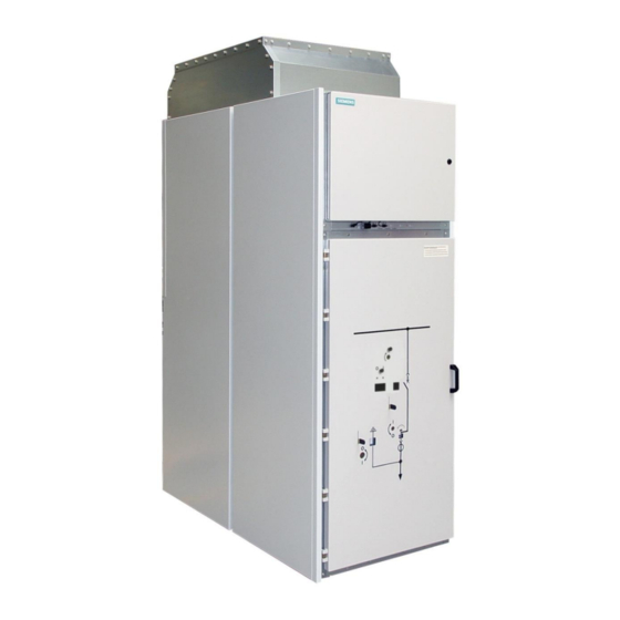
- Page 1 Medium-Voltage Switchgear Air-Insulated Switchgear NXAIR M 24 kV / 25 kA / ≤ 2500 A Busbar Current OPERATING INSTRUCTIONS Order No.: 139-2021.9 Issue: September 2018 Revision: © Siemens AG 2018 All rights reserved.
- Page 2 For details about technical design and equipment sufficiently by these instructions, the matter should like e.g. technical data, secondary equipment, circuit be referred to the competent Siemens department. diagrams, please refer to the order documents. The contents of this instruction manual shall not...
-
Page 3: Safety Instructions
If the damaging situation is not avoided, the product or something in its vicinity may sustain damage. HINT Provides additional information to clarify or simplify a procedure. Observe the hint. Operation symbol: Asks the operator to perform an operation. Result symbol: Identifies the result of an operation. 139-2021.9 / 07 NXAIR M... -
Page 4: Table Of Contents
10.12 Opening the circuit-breaker manually ......................45 10.13 Discharging the spring energy store ......................47 10.14 Charging the spring manually ........................48 10.15 Earthing the feeder manually .........................51 10.16 De-earthing the feeder manually ........................53 10.17 Removing the low-voltage connector ......................56 NXAIR M 139-2021.9 / 07... - Page 5 Verifying safe isolation from supply with the LRM device system ..............128 16.6 CAPDIS and VOIS systems overview ......................129 16.7 Verifying safe isolation from supply with the CAPDIS or VOIS device system ..........132 16.8 Supplier information ............................. 132 139-2021.9 / 07 NXAIR M...
- Page 6 Electronic temperature and humidity controller ....................238 24.4 Applications for temperature controller ......................238 25 Service information ..........................240 25.1 General maintenance ...........................240 25.2 Time schedule for maintenance measures ....................240 25.3 Visual inspection ............................241 25.4 Preventive maintenance ..........................242 NXAIR M 139-2021.9 / 07...
- Page 7 Replacement of panels and components ..................... 248 25.10 Disposal ............................... 248 26 Trouble shooting ........................... 249 26.1 Panels ................................249 27 Index ............................... 251 Document information: Title: Operating Instructions Order number: 139-2021.9 Additional order number: 8BX3300-0LA00-0AD3 Revision: Issue: September 2018 139-2021.9 / 07 NXAIR M...
-
Page 8: General Instructions
Siemens, including documentation of the test results. Maintenance was not done according to the operating instructions of the Siemens products. The edition of the standard is only mentioned in the test report applicable at the time of switchgear manufacture. -
Page 9: Personal Protective Equipment (Ppe)
Access to such a room is restricted to skilled electricians. In the basic version, the degree of protection of the enclosure of NXAIR M medium-voltage switchgear is IP3XD according to IEC 60529. -
Page 10: Update Of The Firmware Of Protection Relays
Update the firmware of the protection relays with the latest firmware version. Siemens protection relays are monitored for their firmware vulnerability. In case that any potential weak points are identified which might allow third parties to access to the protection relay, information concerning this will be distributed by newsletter. -
Page 11: Features
Features Features Features The air-insulated medium-voltage switchgear type NXAIR M has the following features: Factory-assembled, type-tested, metal-enclosed and metal-clad switchgear for indoor installation Type of accessibility A Internal arc classification (IAC): IAC A FLR 25 kA 1 s or IAC A FL 25 kA 1 s according to IEC 62271 Part 200 ... -
Page 12: Technical Data
Disconnectors / earthing switches 62271-102 Switching devices Circuit-breaker / fuse combinations 62271-107 Current limiting fuses 60282-1 Voltage detecting systems 61243-5 Insulation 60071-1 Degree of protection 60529 Current transformers 61869-2 Instrument transformers Voltage transformers 61869-3 Installation, erection 61936-1 NXAIR M 139-2021.9 / 07... -
Page 13: Electromagnetic Compatibility - Emc
A: Type of accessibility A; for authorized personnel only The IAC classification is referred to each panel. The data on the rating plate (see Fig. 1) describes the areas classified for the corresponding panel. 139-2021.9 / 07 NXAIR M... -
Page 14: Panel Dimensions
According to chapter 6 in the Installation Instructions with order number: 139-2019.9 Operating conditions NXAIR M switchgear is designed for normal indoor operating conditions according to IEC 62271-1. In this respect, the following limit values for the ambient air temperature must be complied with: Temperature [ºC]... -
Page 15: Vacuum Circuit-Breaker Type 3Ae
The ambient air must not be significantly polluted by dust, smoke, corrosive and/or flammable gases, vapors or salt. * If NXAIR M is used under other service conditions than normal service conditions acc. to IEC 62271 Part 1 regarding ambient air temperature, the permissible current ratings of feeder and busbar can deviate. In this case, please contact your regional Siemens representative to clarify the permissible current values. -
Page 16: Overview Of Panel Types
Overview of panel types Overview of panel types The withdrawable circuit-breaker switchgear NXAIR M consists of various panel types, which can be freely combined according to the requirements. The following panel types are available: Circuit-breaker panel disconnecting panel ... - Page 17 Overview of panel types for single-busbar system: Fig. 12: Circuit-breaker Fig. 13: Circuit breaker Fig. 15: Circuit-breaker Fig. 14: Circuit-breaker panel, panel A panel, panel B panel, panel B panel, panel A with natural with natural ventilation ventilation 139-2021.9 / 07 NXAIR M...
-
Page 18: Panel Design
Connection for up to 2 cables per phase Feeder earthing switch Contact systems (10) Bushing-type current transformers (11) Bushing-type insulators (12) Busbar (13) Pressure relief duct Fig. 17: Sectional view of circuit-breaker panel with HV HRC fuse design NXAIR M 139-2021.9 / 07... -
Page 19: Basic Design Circuit-Breaker Panel, Double-Busbar System
Block-type current transformers (10) Contact system (11) Voltage transformers (12) Bushing-type insulators (13) Busbars (14) Pressure relief duct (15) Panel B Further information to design features and design options is given in catalog HA 25.71. 139-2021.9 / 07 NXAIR M... -
Page 20: Interlocks
Operating the feeder earthing switch Withdrawable part in test position Operating the busbar earthing switch None (see note given below) Opening the high-voltage door Withdrawable part in test position Closing the high-voltage door Low-voltage connector plugged on NXAIR M 139-2021.9 / 07... -
Page 21: Mechanical Interlocks For Double-Busbar System
Low-voltage connector plugged on Additional electromagnetic interlocks (optional) Action Additional preconditions Racking the withdrawable part General or external release Operating the feeder earthing switch General or external release Operating the busbar earthing switch General or external release 139-2021.9 / 07 NXAIR M... -
Page 22: Additional Padlock Interlock (Optional)
Switching the busbar earthing switch to Access to actuating openings only after CLOSED position opening the lock Switching the busbar earthing switch to Access to actuating openings only after OPEN position opening the lock NXAIR M 139-2021.9 / 07... -
Page 23: Accessories
Fig. 23: Double-bit key with a diameter of 5 mm Fig. 24: Double-bit key with a diameter of 3 mm for unlocking and interlocking the for opening and closing the door to the withdrawable part low-voltage compartment 139-2021.9 / 07 NXAIR M... - Page 24 Fig. 26: Slip-on lever for opening the shutters (optional) (1) for use on left side in panel and (2) for use on right side in panel Fig. 27: Wall-mounting holder for storage of operating tools (optional) NXAIR M 139-2021.9 / 07...
-
Page 25: Service Truck
Service truck versions Depending on the panel version, the following service trucks are included as accessories: Operating side Rear side Operating instructions for service truck Fig. 28: Service truck to insert and remove a withdrawable part 139-2021.9 / 07 NXAIR M... - Page 26 Accessories On the right side of the service truck, there is the pocket for the operating instructions: Fig. 29: Front page of operating instructions Fig. 30: Rear page of operating instructions NXAIR M 139-2021.9 / 07...
- Page 27 Accessories For panels with removable voltage transformers: Operating side Rear side Fig. 31: Service truck to insert and remove the removable voltage transformers 139-2021.9 / 07 NXAIR M...
-
Page 28: Customer Support
For further support, contact the Siemens after-sales service. Repairs Repairs are carried out by trained Siemens technicians, who arrive equipped with original spare parts for the switchgear. Before you call To help us deal with your query more quickly, make sure that the following information is at hand: ... -
Page 29: Operating The Circuit-Breaker Panel
Actuating opening for opening the circuit- (19) breaker Fig. 33: Control elements on the panel front Actuating opening for closing the circuit- (20) breaker Rotary button to close and open the actuating (21) opening located below 139-2021.9 / 07 NXAIR M... -
Page 30: Position Indicators Visible On High-Voltage Door
OPEN position 10.3 Access to compartments Regarding accessibility to the individual compartments, NXAIR M switchgear fulfills the loss of service continuity category LSC 2B according to IEC 62271-200. The degree of protection between the individual compartments is IP2X in standard design. - Page 31 In case of removable voltage transformers (optional): Removable voltage transformers in test position Procedure Pull the door handle upwards and open the high-voltage door. Fig. 34: Opening the high-voltage door of the circuit-breaker panel The high-voltage door is open. 139-2021.9 / 07 NXAIR M...
-
Page 32: Closing The High-Voltage Door
Instruction label on high-voltage door: In addition to these instructions, an instruction label on the high-voltage door describes safe closing of the high-voltage door before executing a switching operation. Fig. 35: Instruction label on high-voltage door NXAIR M 139-2021.9 / 07... - Page 33 Push the door handle on the high-voltage door totally downwards, and release it. Fig. 36: Closing the high-voltage door of the circuit-breaker panel Install a padlock (optional), and close it. The high-voltage door is closed. 139-2021.9 / 07 NXAIR M...
-
Page 34: Positions Of The Withdrawable Circuit-Breaker
Step 1 Step 2 Step 3 Insert and turn double-bit key Insert and turn Turn and remove double-bit key racking crank as far as it will go and from pull it off from 90° 90° NXAIR M 139-2021.9 / 07... -
Page 35: Racking The Withdrawable Circuit-Breaker To Service Position
The actuating opening for racking the withdrawable circuit-breaker is located on the control board of the high-voltage door. Fig. 39: Actuating opening for Fig. 40: Racking crank Fig. 41: Double-bit key, racking the withdrawable diameter 5 mm circuit-breaker 139-2021.9 / 07 NXAIR M... - Page 36 Remove the racking crank for moving the withdrawable circuit-breaker. Turn the double-bit key clockwise as far as it will go (that is 90°) to interlock the withdrawable circuit-breaker. Fig. 44: Turning the double-bit key Fig. 43: Turning the racking crank clockwise clockwise NXAIR M 139-2021.9 / 07...
-
Page 37: Racking The Withdrawable Circuit-Breaker To Test Position
Check through the inspection window in the high-voltage door if the circuit-breaker is in OPEN position. Switch the circuit-breaker to OPEN position, if required. Position indicators of withdrawable circuit-breaker visible on high-voltage door: Fig. 47: Type 3AE5 Fig. 46: Type 3AE1 139-2021.9 / 07 NXAIR M... - Page 38 Lift the operating slide and hold it. To release access to the withdrawable circuit-breaker, insert the double-bit key and turn counter-clockwise as far as it will go (that is 90°). Fig. 51: Releasing access to the withdrawable part NXAIR M 139-2021.9 / 07...
- Page 39 Fit a padlock (optional) to the operating slide and close it. Fig. 54: Position indicator OPEN (test position) The withdrawable circuit-breaker has been racked from service position to test position; the position indicator is in test position (horizontal bar). 139-2021.9 / 07 NXAIR M...
-
Page 40: Closing The Circuit-Breaker Electrically
Spring state indicator for the closing spring shows CHARGED High-voltage door closed Auxiliary voltage for the panel connected Remote or local control Procedure Close the circuit-breaker via central or local electrical control element. NXAIR M 139-2021.9 / 07... -
Page 41: Opening The Circuit-Breaker Electrically
Operating the circuit-breaker discharges and/or charges the spring energy store abruptly. This causes a short loud noise and low vibration. Expect switching noise and low vibration from inside the circuit-breaker. HINT The opening spring is charged during the closing operation. 139-2021.9 / 07 NXAIR M... -
Page 42: Closing The Circuit-Breaker Manually
The requirement of setting the panel to either local or remote control prevents operating the panel locally and centrally at the same time. For operating the circuit-breaker manually, set the panel to local control, for example by switching the local-remote switch to LOCAL position. NXAIR M 139-2021.9 / 07... - Page 43 Spring state indicator for the closing spring shows CHARGED High-voltage door closed Panel set to local control Padlock (optional) removed from the actuating opening Push rod available Fig. 57: High-voltage door with Fig. 58: Push rod actuating opening 139-2021.9 / 07 NXAIR M...
- Page 44 Close the cover of the actuating opening. Optional: Fit a padlock to the actuating opening. The position indicator on the circuit-breaker changes from 0 position to I position. The operations counter is increased by 1. The circuit-breaker is closed. NXAIR M 139-2021.9 / 07...
-
Page 45: Opening The Circuit-Breaker Manually
Withdrawable circuit-breaker in service position or in test position Circuit-breaker in CLOSED position High-voltage door closed Panel set to local control Padlock (optional) removed from actuating opening Push rod available Fig. 62: High-voltage door with actuating opening 139-2021.9 / 07 NXAIR M... - Page 46 Take the push rod out of the actuating opening. Close the cover of the actuating opening. Optional: Fit a padlock to the actuating opening. The position indicator on the circuit-breaker changes from I position to 0 position. The circuit- breaker is open. NXAIR M 139-2021.9 / 07...
-
Page 47: Discharging The Spring Energy Store
Push rod available Procedure The operating sequence is OPEN-CLOSE-OPEN manually. Open the circuit-breaker manually by using the push rod. Close the circuit-breaker manually by using the push rod. Open the circuit-breaker manually by using the push rod. 139-2021.9 / 07 NXAIR M... -
Page 48: Charging The Spring Manually
When the auxiliary voltage is connected, the motor immediately recharges the spring energy store after the closing operation. If the hand crank does not have a freewheel, the hand crank will rotate. Use only the original hand crank with slip coupling. NXAIR M 139-2021.9 / 07... - Page 49 Circuit-breaker in OPEN or CLOSED position Spring state indicator for the closing spring shows NOT CHARGED High-voltage door closed Auxiliary voltage for the panel disconnected Hand crank available Fig. 69: Actuating opening on high-voltage door 139-2021.9 / 07 NXAIR M...
- Page 50 Close access cover of operating shaft using the rotary button. Manual charging of the spring energy store is completed. The energy required for the operating sequence (OPEN-)CLOSE-OPEN is stored in the spring energy store. NXAIR M 139-2021.9 / 07...
-
Page 51: Earthing The Feeder Manually
High-voltage door closed Feeder to be earthed is isolated Withdrawable circuit-breaker in test position Operating lever available Padlock (optional) removed from operating slide For electromagnetic interlock (optional): Electromagnetic interlock deactivated 139-2021.9 / 07 NXAIR M... - Page 52 While keeping the operating slide lifted, insert the operating lever slightly into the actuating opening such that the pins in the operating lever are horizontal. Insert the operating lever in the actuating opening as far as it will go. Fig. 76: Inserting the operating lever NXAIR M 139-2021.9 / 07...
-
Page 53: Earthing The Feeder Manually
Do not try to remove the operating lever at intermediate positions. NOTICE Maloperation If the operating lever is not inserted correctly, the feeder earthing switch may be damaged. Insert the operating lever in the actuating opening as far as it will go. 139-2021.9 / 07 NXAIR M... - Page 54 Operating lever available Padlock (optional) removed from operating slide For electromagnetic interlock (optional): Electromagnetic interlock deactivated Fig. 80: Actuating opening on Fig. 81: Operating lever for operating the high-voltage door feeder earthing switch NXAIR M 139-2021.9 / 07...
- Page 55 180° until the feeder earthing switch changes to OPEN position. Fig. 84: Turning the operating lever Fig. 85: Position indicator counter-clockwise on the high-voltage door in OPEN position Remove the operating lever. 139-2021.9 / 07 NXAIR M...
-
Page 56: Removing The Low-Voltage Connector
Remove the low-voltage connector (2) carefully to the front. Fig. 86: Detaching the low-voltage connector Fig. 87: Removing the low-voltage connector Stow the low-voltage connector into the support located underneath the low-voltage compartment. Fig. 88: Low-voltage connector stowed away NXAIR M 139-2021.9 / 07... -
Page 57: Plugging On The Low-Voltage Connector
In addition to these instructions, an instruction label on the withdrawable circuit- breaker informs about plugging on the low-voltage connector. Follow the advice on the label (3) to push the longitudinal fastener. Fig. 89: Instruction label on withdrawable circuit-breaker 139-2021.9 / 07 NXAIR M... - Page 58 The motor in the circuit-breaker starts up and charges the spring energy store. The position indicator for the spring energy store in the circuit-breaker changes to CHARGED. The low-voltage connector is plugged on and secured by the longitudinal fastener. NXAIR M 139-2021.9 / 07...
-
Page 59: Taking The Withdrawable Circuit-Breaker Out Of The Panel
Service truck available and selected according to the corresponding panel width Withdrawable circuit-breaker racked to test position Spring energy store in the circuit-breaker discharged High-voltage door open Low-voltage connector stowed away 139-2021.9 / 07 NXAIR M... - Page 60 Push the locking elements on the left and right side of the truck into the openings provided for this purpose in the panel frame. Observe that the guide rails of the panel and the service truck are horizontally aligned with each other. Fig. 95: Service truck in front of panel NXAIR M 139-2021.9 / 07...
- Page 61 Fig. 97: Service truck interlocked Unlocking the withdrawable circuit-breaker from the panel To unlock the withdrawable circuit-breaker from the panel frame, turn the two locking levers at the withdrawable circuit-breaker to the outside. Fig. 98: Unlocking the withdrawable circuit-breaker 139-2021.9 / 07 NXAIR M...
- Page 62 Fig. 101: Interlocking the withdrawable circuit-breaker Pull the two unlocking levers on the left and right side of the service truck upwards to release the interlocking with the panel frame. Fig. 102: Unlocking the service truck NXAIR M 139-2021.9 / 07...
- Page 63 Move the service truck away from the panel using the handles. Fig. 103: Moving the service truck If no further operation is executed: Close the high-voltage door. The withdrawable circuit-breaker can now be moved outside the panel on the service truck. 139-2021.9 / 07 NXAIR M...
-
Page 64: Inserting The Withdrawable Circuit-Breaker In A Panel
Risk of damaging safety-relevant parts. Operating the switchgear with a withdrawable part version that is not suitable for the corresponding panel version can cause serious damage to the switchgear. Do not change the mechanical coding or the coding symbols. NXAIR M 139-2021.9 / 07... - Page 65 Circuit-breaker panels with extended control functions are equipped with a second release (a second shunt release / a c.t.-release / an undervoltage release). Extended control functions are coded by a combination of two symbols. 139-2021.9 / 07 NXAIR M...
- Page 66 Carefully compare the coding symbols on the top side of the withdrawable part (1) with the symbols on the top side of the low-voltage connector (2). Fig. 106: Verifying correspondence of coding symbols on withdrawable part and low-voltage connector and (example) NXAIR M 139-2021.9 / 07...
- Page 67 Interlocks placed at the panel front prevent being injured when moving the withdrawable circuit-breaker into the panel. Make sure the service truck is interlocked with the panel before moving the withdrawable circuit-breaker into the panel. Observe the notes and the operating instructions on the service truck. 139-2021.9 / 07 NXAIR M...
- Page 68 Push the locking elements on the left and right side of the service truck into the openings provided for this purpose in the panel frame. Observe that the guide rails of the panel and the service truck are horizontally aligned with each other. Fig. 110: Service truck in front of panel NXAIR M 139-2021.9 / 07...
- Page 69 Fig. 112: Service truck interlocked with panel To release the interlocking of the withdrawable circuit-breaker with the service truck, turn the two locking levers at the withdrawable circuit-breaker to the outside. Fig. 113: Releasing the interlocking of the withdrawable circuit-breaker 139-2021.9 / 07 NXAIR M...
- Page 70 Unlocking the service truck from the panel Pull the two unlocking levers on the left and right side of the service truck upwards to release the interlocking with the panel frame. Fig. 116: Unlocking the service truck NXAIR M 139-2021.9 / 07...
- Page 71 In addition to these instructions, an instruction label on the withdrawable circuit- breaker informs about plugging on the low-voltage connector. Follow the advice on the label (3) to push the longitudinal fastener. Fig. 119: Instruction label on withdrawable circuit-breaker 139-2021.9 / 07 NXAIR M...
- Page 72 The motor in the circuit-breaker starts up and charges the spring energy store. The position indicator for the spring energy store in the circuit-breaker changes to CHARGED. The withdrawable circuit-breaker is inserted in the panel and the high-voltage door is closed. NXAIR M 139-2021.9 / 07...
-
Page 73: Operating The Disconnecting Panel
Fig. 123: Control elements on the panel front 11.2 Position indicators visible on high-voltage door Service position Intermediate position Test position Withdrawable disconnector link: Service position, intermediate position or test position CLOSED OPEN Feeder earthing switch: ─ CLOSED position or OPEN position 139-2021.9 / 07 NXAIR M... -
Page 74: Access To Compartments
Operating the disconnecting panel 11.3 Access to compartments Regarding accessibility to the individual compartments, NXAIR M switchgear fulfills the loss of service continuity category LSC 2B according to IEC 62271-200. The degree of protection between the individual compartments is IP2X in standard design. - Page 75 The procedure for racking the withdrawable disconnector link to service position and/or test position is identical with the procedure for racking the withdrawable circuit-breaker to service position and/or test position. For racking the withdrawable disconnector link to test position, see chapter 10.7 and/or 10.8. 139-2021.9 / 07 NXAIR M...
-
Page 76: Removing Or Plugging On The Low-Voltage Connector
The procedure for earthing and/or de-earthing the feeder in the disconnecting panel is identical with the procedure for earthing and/or de-earthing the feeder in the circuit-breaker panel. For earthing and/or de-earthing the feeder in the disconnecting panel, see chapter 10.15 and/or 10.16. NXAIR M 139-2021.9 / 07... -
Page 77: Operating The Metering Panel
Test sockets for voltage detecting system (11) (type LRM) Fig. 124: Control elements on the panel front 12.2 Position indicators visible on high-voltage door Indicator for position of withdrawable metering part: Service position Intermediate position Test position Position indications for: 139-2021.9 / 07 NXAIR M... -
Page 78: Access To Compartments
Operating the metering panel 12.3 Access to compartments Regarding accessibility to the individual compartments, NXAIR M switchgear fulfills the loss of service continuity category LSC 2B according to IEC 62271-200. The degree of protection between the individual compartments is IP2X in standard design. -
Page 79: Taking The Withdrawable Metering Part Out Of A Panel Or Inserting In A Panel
12.8 Replacing protection fuse-links NOTICE Maloperation Withdrawable metering parts are exclusively designed for operation with specific protection fuse-links. Use only the fuse-link types listed in the following table. Do not mount bridging links instead of protection fuse-links. 139-2021.9 / 07 NXAIR M... - Page 80 Replacing protection fuse-links for rated voltage 24 kV Remove the two plastic bolts M8x35 with the plastic washers 8.4 (1) completely from one of the plastic tubes (2), and keep for later use. Remove the plastic tube, and keep for later use. NXAIR M 139-2021.9 / 07...
- Page 81 Loosen the protection fuse-link by turning back and forth, and pull it out of the voltage transformer housing with mounted contact cap. Detach the contact cap from the protection fuse-link. Fig. 132: Detaching the fuse-link Fig. 133: Removing the Fig. 134: Detaching the fuse-link contact cap 139-2021.9 / 07 NXAIR M...
- Page 82 The protection fuse-links have been replaced. HINT Final procedure Next, insert the withdrawable part in the panel. After closing the high- voltage door, the panel can be integrated into the course of operation again. NXAIR M 139-2021.9 / 07...
-
Page 83: Operating The Circuit-Breaker Panel With Hv Hrc Fuse
Actuating opening for opening the circuit-breaker (19) / fuse combination Actuating opening for closing the circuit-breaker (20) / fuse combination Fig. 136:Control elements on the panel front Rotary button to close and open the actuating (21) opening located below 139-2021.9 / 07 NXAIR M... -
Page 84: Position Indicators Visible On High-Voltage Door
OPEN position 13.3 Access to compartments Regarding accessibility to the individual compartments, NXAIR M switchgear fulfills the loss of service continuity category LSC 2B according to IEC 62271-200. The degree of protection between the individual compartments is IP2X in standard design. -
Page 85: Closing Or Opening The Circuit Breaker / Fuse Combination
Auxiliary voltage for the panel disconnected High-voltage door open Low-voltage connector plugged on Procedure To detach the low-voltage connector, push the longitudinal fastener (1) of the coupling upwards. Remove the low-voltage connector (2) carefully to the front. 139-2021.9 / 07 NXAIR M... - Page 86 If no withdrawable circuit-breaker / fuse combination is inserted in the panel and no further operation is executed: Close the high-voltage door. The removed low-voltage connector is placed at the support located on the left side. NXAIR M 139-2021.9 / 07...
-
Page 87: Plugging On The Low-Voltage Connector
Follow the advice on the label (3) to push the longitudinal fastener. Fig. 140: Instruction label on withdrawable circuit-breaker / fuse combination Take the low-voltage connector out of the support located on the left side. 139-2021.9 / 07 NXAIR M... - Page 88 The motor in the circuit-breaker starts up and charges the spring energy store. The position indicator for the spring energy store in the circuit-breaker changes to CHARGED. The low-voltage connector is plugged on and secured by the longitudinal fastener. NXAIR M 139-2021.9 / 07...
-
Page 89: Taking The Withdrawable Circuit-Breaker / Fuse Combination Out Of A Panel Or Inserting In A Panel
HV HRC fuse-link may have tripped due to a fault. Check the switching-device compartment for deformations when a fuse- link has tripped. Arrangement of HV HRC fuse-links Circuit breaker / fuse combination is equipped with single fuse-link arrangement per phase. 139-2021.9 / 07 NXAIR M... - Page 90 When the high voltage door open, a fuse trip indicator is visible inside the switching-device compartment. Tripped fuse-links can be seen by checking the position of the fuse trip indicator on each phase. The fuse-link has not tripped, if the fuse trip indicator is in the horizontal position. NXAIR M 139-2021.9 / 07...
- Page 91 Selection table for HV HRC fuse-links: Dimension “e” Rated voltage Rated current Order details: [kV] [mm] 3001443.63 3002443.80 3002243.100 3002243.125 Manufacturer information: www.siba-fuses.com Further information to all rated current of fuses and technical data is given in catalog HA 25.71. 139-2021.9 / 07 NXAIR M...
- Page 92 When the withdrawable part is taken out of the panel, fuse assemblies are accessible for the replacement of the HV HRC fuse-links. HINT Hereafter, the disassembly of those parts is described, which are later assembled again at the same place. Store disassembled parts carefully and keeps them available for later reuse. NXAIR M 139-2021.9 / 07...
- Page 93 First, select one of the outer phases L1 or L3. Remove the insulation covers from the fuse assembly. Push the clips towards the front insulation cover (2) from the right and left side until it is unlocked. Fig. 148: Pushing the clips towards the front insulation cover from the both side 139-2021.9 / 07 NXAIR M...
- Page 94 Fig. 150: Pushing the clips towards the rear insulation cover from the both side Then take the rear insulation cover out of the fuse assembly and keep it for later use. Fig. 151: Removing the rear insulation cover NXAIR M 139-2021.9 / 07...
- Page 95 Pull the HV HRC fuse-link at the end upwards out of the clip of the fuse holder. Fig. 153: Pulling the HV HRC fuse-link at the end Take the HV HRC fuse-link out of the fuse holder and check empty fuse holder for damages. 139-2021.9 / 07 NXAIR M...
- Page 96 / fuse combination.The position of the striker is identified with a triangle representing an arrow on the rating plate of the HV HRC fuse-link. Fig. 156: Triangle representing Fig. 155: Inserting the HV HRC fuse-link an arrow NXAIR M 139-2021.9 / 07...
- Page 97 Insert the rear insulation cover into the housing and push it until the click noise is heard. Fig. 158: Pushing rear insulation cover into the housing Insert the front insulation cover into the housing and push it until the click noise is heard. 139-2021.9 / 07 NXAIR M...
- Page 98 The HV HRC fuse-links have been replaced. HINT Final procedure Insert the withdrawable part in the panel and de-earth the feeder. After closing the high-voltage door, the panel can be integrated into the course of operation again. NXAIR M 139-2021.9 / 07...
-
Page 99: Operating The Circuit-Breaker Panel For Double-Busbar System
Actuating opening for opening the circuit- circuit-breaker panel for double-busbar (19) breaker system, panel A Actuating opening for closing the circuit- (20) breaker Rotary button to close and open the actuating (21) opening located below 139-2021.9 / 07 NXAIR M... - Page 100 Actuating opening for closing the circuit- (20) breaker Rotary button to close and open the actuating (21) opening located below Fig. 162: Control elements on the panel front of the circuit-breaker panel for double-busbar system, panel B NXAIR M 139-2021.9 / 07...
-
Page 101: Position Indicators Visible On High-Voltage Door, Panel A
NOT CHARGED position Access to compartments 14.4 Regarding accessibility to the individual compartments, NXAIR M switchgear fulfills the loss of service continuity category LSC 2B according to IEC 62271-200. The degree of protection between the individual compartments is IP2X in standard design. -
Page 102: Opening Or Closing The High-Voltage Door
For discharging and/or charging the closing spring in the circuit-breaker panel for double- and/or busbar system, see chapter 10.13 10.14. NXAIR M 139-2021.9 / 07... -
Page 103: Earthing Or De-Earthing The Feeder
10.19 and/or 10.20. 139-2021.9 / 07 NXAIR M... -
Page 104: Operating The Removable Voltage Transformers
For opening and/or closing the high-voltage door at the panel with removable voltage transformers, see chapter 10.4 and/or 10.5. NXAIR M 139-2021.9 / 07... -
Page 105: Racking The Removable Voltage Transformers To Service Position
If the removable voltage transformers are not correctly positioned in the panel, damages may occur when the removable voltage transformers are racked. If you hear a noise or if you notice a resistance, stop racking immediately. Inform the regional Siemens representative. Fig. 165: Racking tool for the removable voltage transformers Preconditions ... - Page 106 Fig. 168: Inserting the racking tool Push the racking tool into the door as far as it will go. Turn the racking tool 90° counter-clockwise to unlock the racking mechanism. Fig. 169: Turning the racking tool 90° counter-clockwise for unlocking NXAIR M 139-2021.9 / 07...
- Page 107 (end position). Fig. 170: Pushing the racking tool to rack Turn the racking tool 90° clockwise to lock the racking mechanism. Fig. 171: Turning 90° clockwise to lock 139-2021.9 / 07 NXAIR M...
- Page 108 To close the actuating opening, push the operating slide down as far as it will go. Fit a padlock to the operating slide and close it. Fig. 173: Fitting a padlock The removable voltage transformers are in service position. NXAIR M 139-2021.9 / 07...
-
Page 109: Racking The Removable Voltage Transformers To Test Position
If the removable voltage transformers are not correctly positioned in the panel, damages may occur when the removable voltage transformers are racked. If you hear a noise or if you notice a resistance, stop racking immediately. Inform the regional Siemens representative. Fig. 174: Racking tool for the removable voltage transformers Preconditions ... - Page 110 Fig. 177: Inserting the racking tool Push the racking tool into the door as far as it will go. Turn the racking tool 90° counter-clockwise to unlock the racking mechanism. Fig. 178: Turning the racking tool 90° counter-clockwise to unlock NXAIR M 139-2021.9 / 07...
- Page 111 To rack the removable voltage transformers, pull the racking tool as far as it will go (end position). Fig. 179: Pulling the racking tool to rack Turn the racking tool 90° clockwise to lock the racking mechanism. Fig. 180: Turning 90° clockwise to lock 139-2021.9 / 07 NXAIR M...
- Page 112 To close the actuating opening, push the operating slide down as far as it will go. Fit a padlock to the operating slide and close it. Fig. 182: Fitting a padlock The removable voltage transformers are in test position. NXAIR M 139-2021.9 / 07...
-
Page 113: Taking The Removable Voltage Transformers Out Of The Panel
To detach the low-voltage connector, push the longitudinal fastener (1) of the coupling downwards. Remove the low-voltage connector (2) carefully upwards. Fig. 183: Detaching and removing the low-voltage connector Stow the low-voltage connector away in the shelf on the left inside the panel. 139-2021.9 / 07 NXAIR M... - Page 114 Move the service truck centrally in front of the panel. The guide lugs bring the service truck to the correct position at the panel frame. Fig. 185: Moving the service truck centrally in front of the panel NXAIR M 139-2021.9 / 07...
- Page 115 To check whether the service truck is correctly interlocked with the panel, pull the service truck backwards using the handle. Fig. 188: Pulling the service truck back to check interlocking The service truck is interlocked with the panel. 139-2021.9 / 07 NXAIR M...
- Page 116 Removing the service truck with the removable voltage transformers on top from the panel To detach the locking levers from the panel frame, pull the locking levers on the left and right side of the service truck. Fig. 191: Detaching the locking levers NXAIR M 139-2021.9 / 07...
-
Page 117: Inserting The Removable Voltage Transformers In A Panel
High-voltage door open Withdrawable part in the panel or removed from the panel Low-voltage connector stowed away in the shelf on the left inside the panel Removable voltage transformers ready on service truck 139-2021.9 / 07 NXAIR M... - Page 118 Fig. 193: Moving the service truck centrally in front of the panel If necessary, adjust the height of the service truck with the 4 bolts to compensate unevenness in the floor. Fig. 194: Adjusting the height with the bolts NXAIR M 139-2021.9 / 07...
- Page 119 Inserting the removable voltage transformers in the panel To undo the interlocking between the removable voltage transformers and the service truck, push the lever to the left and hold it. Fig. 197: Pushing the lever to unlock 139-2021.9 / 07 NXAIR M...
- Page 120 Removing the service truck from the panel To detach the locking levers from the panel frame, pull the locking levers on the left and right side of the service truck. Fig. 200: Detaching the locking levers NXAIR M 139-2021.9 / 07...
- Page 121 Follow the advice on the label (3) to push the longitudinal fastener Fig. 202: Instruction label on removable voltage transformers Take the low-voltage connector out of the shelf on the left inside the panel. Fig. 203: Low-voltage connector stowed away 139-2021.9 / 07 NXAIR M...
-
Page 122: Replacing Protection Fuse-Links
Do not mount bridging links instead of protection fuse-links. HINT Tripped protection fuse-links can cause hidden damages on the other protection fuse-links. Always replace all protection fuse-links, even if only one protection fuse-link has tripped. NXAIR M 139-2021.9 / 07... - Page 123 Removable voltage transformers taken out of the panel Set of proper protection fuse-links available Procedure Move the service truck with the removable voltage transformers away from the panel. The protection fuse-links are accessible. Fig. 206: Protection fuse-links are accessible 139-2021.9 / 07 NXAIR M...
- Page 124 The protection fuse-links have been replaced. HINT Final procedure Next, insert the removable voltage transformers in the panel. After closing the high-voltage door, the panel can be integrated into the course of operation again. NXAIR M 139-2021.9 / 07...
-
Page 125: Verifying Safe Isolation From Supply
CAPDIS and VOIS device systems installed in the door to the low-voltage compartment LRM device system as an indicator with the associated measuring system installed below the door to the low-voltage compartment Fig. 209: Test sockets for feeder Fig. 210: Test sockets for busbar 139-2021.9 / 07 NXAIR M... -
Page 126: Lrm System Overview
Phase isolated from supply up or flash NOTICE Device system LRM Before verifying safe isolation from supply with the LRM device system, do absolutely check proper functioning of the LRM-ST voltage indicator. Fig. 212: LRM-ST voltage indicator NXAIR M 139-2021.9 / 07... -
Page 127: Verifying Lrm-St Voltage Indicator
Perform the test. The test of the LRM-ST voltage indicator is completed. If the voltage indicator does not pass the function test, do not use this voltage indicator to verify safe isolation from supply. 139-2021.9 / 07 NXAIR M... -
Page 128: Verifying Safe Isolation From Supply With The Lrm Device System
Plug the LRM-ST voltage indicator into the test socket. Fig. 214: Cover removed from Fig. 215: LRM-ST voltage indicator test socket L1 on L1 Read the voltage indication at the LRM-ST. Fig. 216: LRM-ST indication NXAIR M 139-2021.9 / 07... -
Page 129: Capdis And Vois Systems Overview
16.6 CAPDIS and VOIS systems overview CAPDIS-S1+ Integrated capacitive voltage detecting system CAPDIS-S2+ Integrated capacitive voltage monitoring system with relay output VOIS+ Economic integrated capacitive voltage detecting system Economic integrated capacitive voltage detecting system with relay VOIS-R+ output 139-2021.9 / 07 NXAIR M... - Page 130 Fig. 218: VOIS+, cover open “Test” button Cover LC display Duct for signaling cables CAPDIS-M Fig. 219: CAPDIS-S2+, cover closed Test socket L2 Earth socket Test socket L3 Test socket L1 Short instructions Fig. 220: CAPDIS-S2+, cover open NXAIR M 139-2021.9 / 07...
- Page 131 Degree of protection IP54 Degree of protection IP54 With integrated 3-phase test socket for phase With integrated 3-phase test socket for phase comparison comparison ─ With signal-lead test Integrated repeat test of the ─ interfaces 139-2021.9 / 07 NXAIR M...
-
Page 132: Verifying Safe Isolation From Supply With The Capdis Or Vois Device System
16.8 Supplier information Further information for the devices to get from: Device Supplier: VOIS+ / VOIS-R+ / www.kries.com CAPDIS-S1+ / CAPDIS-S2+ LRM system www.horstmanngmbh.com LRM-ST voltage indicator Siemens AG / Order No.: 8DX1620 NXAIR M 139-2021.9 / 07... -
Page 133: Earthing And De-Earthing The Busbar System
Observe the manual and the instructions on the ladder: NOTICE Maloperation A switching operation once started must be completed totally! A switching operation that was not completed cannot be turned back. Do not try to remove the operating lever at intermediate positions. 139-2021.9 / 07 NXAIR M... - Page 134 Procedure Ensure that the intended manual switching operation has been released externally. Make sure according to the panel number at the panel that the release for manual earthing of exactly this panel is available. NXAIR M 139-2021.9 / 07...
- Page 135 The actuating opening for the busbar earthing switch has different receptacles for inserting the operating lever for closing and opening the busbar earthing switch. Fig. 227: Actuating opening for Fig. 228: Inserting the operating lever busbar earthing switch for closing 139-2021.9 / 07 NXAIR M...
- Page 136 While turning the operating lever, the position indicator of the busbar earthing switch changes from the OPEN position to the intermediate position. Fig. 232: Position indicator in intermediate position NXAIR M 139-2021.9 / 07...
- Page 137 The position indicator of the busbar earthing switch changes from the OPEN position via the intermediate position to the CLOSED position. Fig. 234: Operating slide on busbar earthing switch padlocked The busbar system is earthed. 139-2021.9 / 07 NXAIR M...
-
Page 138: Earthing The Busbar System Manually
Do not try to remove the operating lever at intermediate positions. NOTICE Maloperation If the operating lever is not inserted correctly, the busbar earthing switch may be damaged. Insert the operating lever in the actuating opening as far as it will go. NXAIR M 139-2021.9 / 07... - Page 139 Ensure that the intended manual switching operation has been released externally. Make sure according to the panel number at the panel that the release for manual de- earthing of exactly this panel is available. Position the electrician's ladder correctly in front of the panel. 139-2021.9 / 07 NXAIR M...
- Page 140 The actuating opening for the busbar earthing switch has different receptacles for inserting the operating lever for closing and opening the busbar earthing switch. Fig. 240: Actuating opening for Fig. 241: Inserting the operating lever busbar earthing switch for opening NXAIR M 139-2021.9 / 07...
- Page 141 While turning the operating lever, the position indicator of the busbar earthing switch changes from the CLOSED position to the intermediate position. Fig. 245: Position indicator in intermediate position 139-2021.9 / 07 NXAIR M...
- Page 142 The position indicator of the busbar earthing switch changes from the CLOSED position via the intermediate position to the OPEN position. Fig. 247: Operating slide on busbar earthing switch padlocked The busbar system is de-earthed. NXAIR M 139-2021.9 / 07...
-
Page 143: Operating The Shutters
The mechanism for the shutters on the left and right side in the switching-device compartment can cause injuries by getting squeezed, caught or cut. Do not remove any parts of the covering. Do not reach into the shutter mechanism with hands or tools. 139-2021.9 / 07 NXAIR M... - Page 144 Padlock the shutter mechanism on the right side in the switching-device compartment. Fig. 249: Padlocking the shutter mechanism on the right side in the switching-device compartment Push the slip-on lever (marked with L) on the shutter mechanism on the left side in the switching-device compartment. NXAIR M 139-2021.9 / 07...
- Page 145 Fig. 252: Shutter to busbar compartment open The shutter to the busbar compartment is open. HINT Final procedure Immediately proceed to perform a voltage test with recommended suitable equipment or other intended operations. 139-2021.9 / 07 NXAIR M...
-
Page 146: Operating The Shutter To The Connection Compartment In The Switching-Device Compartment
Always operate the slip-on lever outside the panel using the handle. Always close the shutter to the connection compartment: Before interrupting operations inside the switching-device compartment. Immediately after completing operations inside the switching-device compartment. NXAIR M 139-2021.9 / 07... - Page 147 Padlock the shutter mechanism on the left side in the switching-device compartment. Fig. 254: Padlocking the shutter mechanism on the left side in the switching-device compartment Push the slip-on lever (marked with R) on the shutter mechanism on the right side in the switching-device compartment. 139-2021.9 / 07 NXAIR M...
- Page 148 Fig. 257: Shutter to the connection compartment open The shutter to the connection compartment is closed. HINT Final procedure Immediately proceed to perform a voltage test with recommended suitable equipment or other intended operations. NXAIR M 139-2021.9 / 07...
- Page 149 Push the handle of the slip-on lever slightly to the left (to release the latch) and let it slip upwards. The shutter closes. Remove the slip-on lever. Remove the padlock from the left side in the switching-device compartment. The shutter to the connection compartment is closed. 139-2021.9 / 07 NXAIR M...
-
Page 150: Accessing The Connection Compartment Through The Front
HINT Hereafter, the disassembly of those parts is described, which are later assembled again at the same place. Store disassembled parts and bolting material carefully, and keep them available for later reuse. NXAIR M 139-2021.9 / 07... - Page 151 An additional position indicator of the feeder earthing switch is visible inside the switching-device compartment. The feeder earthing switch is earthed if the additional position indicator points to the vertical I symbol. Fig. 259: Additional position indicator of feeder earthing switch in the switching-device compartment 139-2021.9 / 07 NXAIR M...
-
Page 152: Accessing The Connection Compartment Through The Switching-Device Compartment
4 nuts M8 with contact washers Remove the protection plate of the switching-device compartment (1) from the switching- device compartment, and store it. Fig. 260: 4 bolted joints on protection plate of switching-device compartment NXAIR M 139-2021.9 / 07... -
Page 153: Installing The Vertical Partition In The Switching-Device Compartment
Without isolation from supply, the cables / bars in the connection compartment will be live at operational high voltage. Observe the Five Safety Rules. Verify safe isolation from supply. Do not operate the feeder earthing switch during any activities inside or near the connection compartment. 139-2021.9 / 07 NXAIR M... - Page 154 Damages inside the switching-device compartment due to incorrect or incomplete installation of the partition. To fasten the partition, always assemble all bolted joints of the partition all around, and screw them in up to the end of the thread. NXAIR M 139-2021.9 / 07...
- Page 155 To fix the partition (2), tighten the bolts all around hand-tight: 13 bolts M8x20 with contact washers and plain washers (4) 2 bolts M8x20 with contact washers (3) Tighten the fixing bolts all around with a tightening torque of 25 Nm. 139-2021.9 / 07 NXAIR M...
- Page 156 Tighten the fixing bolts (5) with a tightening torque of 25 Nm. Fig. 264: 4 bolted joints on protection plate of switching-device compartment The partition between the connection compartment and the switching-device compartment is installed. NXAIR M 139-2021.9 / 07...
-
Page 157: Accessing The Connection Compartment Through The Switching-Device Compartment In Panel Versions With Ventilation System
The metal parts of the ventilation duct and the vertical partition may have sharp edges. Put on personal protective equipment. CAUTION High weight The ventilation duct is heavy. Remove the ventilation duct absolutely with 2 persons. Put on personal protective equipment. 139-2021.9 / 07 NXAIR M... - Page 158 Detach the holder of the air guide. To do this, loosen the lower bolt (2), and unscrew and store the upper bolt (1). Proceed in the same way on the other side. Fig. 266: Bolts for detaching the holder NXAIR M 139-2021.9 / 07...
- Page 159 Fig. 269: 3 bolted joints on partition Unscrew the lateral bolts from the partition and the base frame, and store them. Proceed in the same way on the other side. Fig. 270: 6 lateral bolted joints on partition and base frame 139-2021.9 / 07 NXAIR M...
- Page 160 Please observe during all other removal and installation work that the links on the panel base are not dented. Fig. 275: 2 links on panel base Fig. 276: Correct position of the links NXAIR M 139-2021.9 / 07...
- Page 161 16 bolts M8x20 and plain washers (4) Remove the partition (2), and store it. Fig. 278: 16 bolted joints on partition Access to the connection compartment through the panel front is given. 139-2021.9 / 07 NXAIR M...
-
Page 162: Installing The Vertical Partition And The Ventilation Duct In The Switching-Device Compartment
Some parts and surfaces of the switchgear are greased for functioning. Do not remove the grease there; do not clean the parts and surfaces. If greased areas are dirty, clean the dirty area and grease again according to the maintenance instructions. NXAIR M 139-2021.9 / 07... - Page 163 Protection plate and associated bolting material available: 4 nuts M8 with contact washers Vertical partition and associated bolting material available: 16 bolts M8x20 with contact washers and plain washers Ventilation duct and associated bolting material available 139-2021.9 / 07 NXAIR M...
- Page 164 Fix the protection plate (1) by bolting the nuts (5) hand-tight: 4 nuts M8 with contact washers Tighten the fixing nuts (5) with torque 25 Nm. Fig. 281: 4 bolted joints on protection plate of switching-device compartment NXAIR M 139-2021.9 / 07...
- Page 165 Set the ventilation duct down centrally on the base frame of the panel. The side of the ventilation duct holding the air guide (1) must border on the vertical partition. Fig. 285: Ventilation duct placed centrally on the panel base frame 139-2021.9 / 07 NXAIR M...
- Page 166 Fig. 287: 6 lateral bolted joints on partition and base frame Fasten the upper bolts size M8x20 with contact washers at the vertical partition hand-tight. Tighten the bolts with torque 25 Nm. Fig. 288: 3 bolted joints on partition NXAIR M 139-2021.9 / 07...
- Page 167 Now the panel can be integrated into the course of operation again, for example: Inserting the withdrawable part in the panel. Closing the high-voltage door. De-earthing the feeder. Racking the withdrawable part to service position. 139-2021.9 / 07 NXAIR M...
-
Page 168: Accessing The Connection Compartment Through The Switching-Device Compartment In Panel Versions With Voltage Transformer Compartment
Put on personal protective equipment. Preconditions Preparations as described in chapter 19.1 completed Withdrawable circuit-breaker in test position High-voltage door open Removable voltage transformers removed from panel as described in chapter 15.5 NXAIR M 139-2021.9 / 07... - Page 169 Take the voltage transformer compartment (3) out of the panel to the front, and store it. Remove 4 nuts M8 at the protection plate of the switching-device compartment, and store them. Fig. 295: 4 bolted joints on protection plate of switching-device compartment 139-2021.9 / 07 NXAIR M...
- Page 170 Loosen the 3 connecting cables (8) for the removable voltage transformers from the cable connections. 6 bolted joints M8x20 of the bushing plate with bushings, and store them. Fig. 298: 6 bolted joints on bushing plate with bushings NXAIR M 139-2021.9 / 07...
- Page 171 Remove the bushing plate with bushings (5) from the switching-device compartment, and store it. Fig. 299: Switching-device compartment prepared for cable installation from the front The connection compartment is accessible through the switching-device compartment. 139-2021.9 / 07 NXAIR M...
-
Page 172: Installing The Bushing Plate, The Vertical Partition And The Voltage Transformer Compartment In The Switching-Device Compartment
Some parts and surfaces of the switchgear are greased for functioning. Do not remove the grease there; do not clean the parts and surfaces. If greased areas are dirty, clean the dirty area and grease again according to the maintenance instructions. NXAIR M 139-2021.9 / 07... - Page 173 Install the bushing plate with bushings. Fix the partition (5) by screwing the bolts in all around hand-tight: 6 bolts M8x20 with contact washers and plain washers Tighten the bolts with torque 25 Nm. 139-2021.9 / 07 NXAIR M...
- Page 174 Fig. 301: Bolted joints at the cable connections Insert the partition (2), and fasten with 8 bolts M8x20 with contact washers and plain washers. Tighten the bolts with torque 25 Nm. Fig. 302: 8 bolted joints on partition NXAIR M 139-2021.9 / 07...
- Page 175 Insert the wiring duct cover (4), and fasten with 3 / 5 bolts M8x20 with contact washers. Tighten the bolts with torque 25 Nm. Fig. 306: 3 bolted joints on wiring duct cover, Fig. 307: 5 bolted joints on wiring duct cover, panel width 800 mm panel width 1000 mm 139-2021.9 / 07 NXAIR M...
- Page 176 Now the panel can be integrated into the course of operation again, for example: Inserting the withdrawable part in the panel. Closing the high-voltage door. De-earthing the feeder. Racking the withdrawable part to service position. NXAIR M 139-2021.9 / 07...
-
Page 177: Accessing The Connection Compartment Through The Rear
If an activity inside the connection compartment is interrupted. Immediately after an activity inside the connection compartment was completed. CAUTION Sharp edges The metal parts of the rear wall may have sharp edges. Put on personal protective equipment. NXAIR M 139-2021.9 / 07... - Page 178 Access to the connection compartment through the rear side of the panel is described hereafter by the example of a 4-panel arrangement with 48 bolted joints size M8x20. Fig. 310: 4-panel arrangement with rear wall and rear ledges closed (as an example) NXAIR M 139-2021.9 / 07...
- Page 179 Unscrew and remove the bolting material at the panel base: 4 bolts M8x20 with contact washers (5) To remove the rear wall, lift it and pull it away using the handle (4). Store the rear wall. 139-2021.9 / 07 NXAIR M...
-
Page 180: Installing The Rear Wall On The Connection Compartment
Do not remove any ledges on the rear side of the busbar compartment. CAUTION Sharp edges The metal parts of the rear wall may have sharp edges. Put on personal protective equipment. NXAIR M 139-2021.9 / 07... - Page 181 Insert the rear wall (1) at the rear side of the panel and push the wall down using the handle. Fix the rear wall by screwing the lower bolts in hand-tight: 4 bolts M8x20 with contact washers (2) Tighten the bolts with torque 25 Nm. 139-2021.9 / 07 NXAIR M...
- Page 182 Proceed in the same way with the other vertical ledge. (3) Sealing brackets (4) Horizontal ledge (5) Vertical ledges Fig. 314: Installing ledges and brackets The rear wall is installed on the connection compartment. NXAIR M 139-2021.9 / 07...
-
Page 183: Accessing The Connection Duct Through The Rear Side Of The Panel
If an activity inside the connection duct is interrupted. Immediately after an activity inside the connection duct was completed. CAUTION Sharp edges The metal parts of the rear walls may have sharp edges. Put on personal protective equipment. 139-2021.9 / 07 NXAIR M... - Page 184 Fig. 315: Position indicator on high-voltage door Remove the connecting elements from the horizontal ledge (3): 12 / 14 bolts M8x20 with contact washers Remove the horizontal ledge, and store it together with the associated connecting elements. NXAIR M 139-2021.9 / 07...
- Page 185 4 / 5 bolts M8x20 with contact washers To remove, pull the upper rear wall (4) downwards by the handle. Store the rear wall. Access to the connection duct through the rear side is given. 139-2021.9 / 07 NXAIR M...
-
Page 186: Installing The Rear Walls On The Connection Duct
Danger due to damages Possible malfunctioning and switchgear damage caused by foreign objects: Remove all foreign objects from the connection duct, for example: Tools Unused installation material Packing material Cleaning material NXAIR M 139-2021.9 / 07... - Page 187 Install one of the 4 vertical ledges (5). Fix it by screwing the bolts in hand-tight: 9 / 19 bolts M8x20 with contact washers and plain washers size 8 acc. to ISO 7093 Proceed in the same way with the other vertical ledges. 139-2021.9 / 07 NXAIR M...
- Page 188 The rear walls are installed on the connection duct. HINT Final procedure steps Now the panel can be integrated into the course of operation again, for example: De-earthing the feeder. Racking the withdrawable part to service position. NXAIR M 139-2021.9 / 07...
-
Page 189: Key-Operated Interlocks
A cover protects the locks against accidental access. The cover is secured on the high-voltage door with a rotary button. (1) Cover Rotary button to secure the cover Fig. 318: Example: High-voltage door with key-operated interlocks, protected with cover 139-2021.9 / 07 NXAIR M... - Page 190 Example: The feeder earthing switch is in CLOSED position (2). To release switching to OPEN, insert the associated key (1) as far as it will go, and turn clockwise. Fig. 320: Example: Interlocking / releasing switching to OPEN NXAIR M 139-2021.9 / 07...
-
Page 191: Key-Operated Interlocks For The Busbar Earthing Switch
OPEN position. Key release: only when busbar earthing switch is in OPEN position Key release: only when busbar earthing switch is in CLOSED position Fig. 321: Door to low-voltage compartment with key-operated interlocks 139-2021.9 / 07 NXAIR M... - Page 192 (1), and turn clockwise as far as it will go (2). Fig. 325: Position indicator for busbar earthing switch: CLOSED Fig. 324: Releasing switching to OPEN The selected operating function is interlocked / released. NXAIR M 139-2021.9 / 07...
-
Page 193: Fitting The Earthing Device
(2) Limiting ring (3) Hand area (4) Cross bar (5) Earthing clamp (6) Screw handle of the earthing clamp (7) Spindle of the earthing tulip (8) Earthing tulips Fig. 326: Earthing accessories and earthing rod 139-2021.9 / 07 NXAIR M... -
Page 194: Connecting The Earthing Device
Inspection of the earthing accessories is successfully executed. 22.2 Connecting the earthing device DANGER Electric shock Put on personal protective equipment. Observe the correct order of action: Attach the earthing clamp to the earthing point of the panel before opening a shutter. NXAIR M 139-2021.9 / 07... - Page 195 Personal protective equipment put on Upper shutter covering bushing contacts linked with busbar compartment Lower shutter covering bushing contacts linked with connection compartment Fig. 329: Panel prepared Fig. 330: Fixed earthing point for connecting the earthing clamp 139-2021.9 / 07 NXAIR M...
- Page 196 Bolt the earthing clamp hand-tight to the earthing point of the panel using the screw handle. This corresponds to a tightening torque of approx. 20 Nm. Fig. 331: Bolting the earthing clamp Fig. 332: Earthing clamp connected with earthing point NXAIR M 139-2021.9 / 07...
- Page 197 Do not reach into or enter the switching-device compartment. Do not insert any objects in the switching-device compartment other than the earthing rod. Always close a shutter: Before interrupting operations inside the switching-device compartment. Immediately after completing operations inside the switching-device compartment. 139-2021.9 / 07 NXAIR M...
- Page 198 After isolation, the busbar system still carries some capacitive charging. Expect short light and noise from a minor electrostatic discharge while leading the earthing rod with the earthing tulip on top towards the bushing contact. NXAIR M 139-2021.9 / 07...
- Page 199 Continue pushing the earthing rod slightly towards the bushing contact. While doing so, carefully turn the earthing rod clockwise at the cross lever to fix the earthing tulip on the bushing contact. 139-2021.9 / 07 NXAIR M...
- Page 200 To earth the outer bushing contacts, proceed in the same way. Fig. 338: Earthing tulip fixed on central Fig. 339: Earthing device completely bushing contact mounted The earthing device is completely mounted. NXAIR M 139-2021.9 / 07...
-
Page 201: Removing The Earthing Device
Use the earthing accessories only in the way described hereafter. Never reach out beyond the limiting ring on the earthing rod. This ensures a safe distance to the bushing contacts. 139-2021.9 / 07 NXAIR M... - Page 202 Fig. 342: Plugging the earthing rod onto the tulip Continue pushing the earthing rod slightly towards the earthing tulip. While doing so, carefully turn the earthing rod counter-clockwise at the cross lever in order to loosen the earthing tulip. NXAIR M 139-2021.9 / 07...
- Page 203 Closing the shutter DANGER Electric shock Close the shutter strictly as described in chapter 18 “Operating the shutters”, but leave the other shutter padlocked. Close the shutter as described in chapter 18 “Operating the shutters”. 139-2021.9 / 07 NXAIR M...
- Page 204 Fig. 347: Unscrewing the with earthing point earthing clamp Remove the earthing device from the switching-device compartment. Remove the padlock from the mechanism of the other shutter. The earthing device is completely detached from the bushing contacts. NXAIR M 139-2021.9 / 07...
-
Page 205: Panels With Motor Operating Mechanism Control
Depending on the design of the panel version, switching between local and central control is carried out in different ways, for example via a local-remote switch located on the door to the low-voltage compartment. Fig. 348: Example of a local-remote switch 139-2021.9 / 07 NXAIR M... - Page 206 An indicator on the high-voltage door informs about the selected access mode: Fig. 351: Control door open, Fig. 352: Access mode indicator for access mode indicator visible racking: possible indications NXAIR M 139-2021.9 / 07...
- Page 207 Withdrawable circuit-breaker in test position Panel set to local control HINT Blocking any racking operation is the precondition for opening the high-voltage door. Before opening the high-voltage door, set the access mode indicator to “T”. 139-2021.9 / 07 NXAIR M...
- Page 208 Low-voltage connector plugged Closing the feeder Closing the feeder earthing switch High-voltage door closed electrically during service is earthing switch electrically Control door closed during service interlocked electrically. Withdrawable circuit-breaker in service position NXAIR M 139-2021.9 / 07...
-
Page 209: Opening The Control Door
Instruction label on control door In addition to these instructions, an instruction label provided on the control door informs about opening the control door. Fig. 353: High-voltage door: instruction label about opening the control door 139-2021.9 / 07 NXAIR M... -
Page 210: Closing The Control Door
Preconditions High-voltage door open or closed Padlock for control door available Procedure Pull the handle upwards and hold it. Press the control door totally against the high-voltage door. NXAIR M 139-2021.9 / 07... -
Page 211: Selecting Manual Operation For Racking
For any local operations ─ manual or electrical ─ set the panel to local control, for example by switching the local-remote switch to LOCAL position. Fig. 358: Access mode indicator for racking: starting point “M” or “T” 139-2021.9 / 07 NXAIR M... - Page 212 “H”: To change from “M” to “H” turn 90° counter-clockwise To change from “T” to “H” turn 90° clockwise from from Fig. 360: Turning the key counter-clockwise Fig. 361: Turning the key clockwise NXAIR M 139-2021.9 / 07...
-
Page 213: Selecting Electrical Operation For Racking
Electrical racking is only possible when both the high-voltage door and the control door are closed. After releasing electrical access to the withdrawable circuit-breaker, close the control door and padlock it. Fig. 362: Access mode indicator for racking: starting point “H” 139-2021.9 / 07 NXAIR M... -
Page 214: Selecting Interlocking
LOCAL position. HINT Blocking any racking operation is the precondition for opening the high-voltage door. Before opening the high-voltage door, set the access mode indicator to “T”. NXAIR M 139-2021.9 / 07... - Page 215 To release the actuating opening for the double-bit key, lift the operating slide (1) and hold it. Insert the double-bit key (2). Fig. 365: Lifting the operating slide and inserting the key: starting point “M” 139-2021.9 / 07 NXAIR M...
- Page 216 HINT When the control door is closed, the access mode indicator for the withdrawable circuit-breaker is covered. If required, open the control door to read the indicator. Racking the withdrawable circuit-breaker is blocked. NXAIR M 139-2021.9 / 07...
-
Page 217: Racking The Withdrawable Circuit-Breaker To Service Position Manually
Incorrect stress of the motor operating mechanism When the withdrawable circuit-breaker is racked manually, the motor operating mechanism is also turned via the wheel chain mechanism. Turn the racking crank slowly and uniformly to avoid high reverse polarity voltage. 139-2021.9 / 07 NXAIR M... - Page 218 Feeder earthing switch in OPEN position Circuit-breaker in OPEN position Panel set to local control Control door open Double-bit key for selecting racking mode inserted and access mode indicator shows “H” NXAIR M 139-2021.9 / 07...
- Page 219 To close the actuating opening, push the operating slide down as far as it will go. Close the control door. Fit a padlock to the control door and close the padlock. The withdrawable circuit-breaker has been manually racked from test position to service position. 139-2021.9 / 07 NXAIR M...
-
Page 220: Racking The Withdrawable Circuit-Breaker To Service Position Electrically
The requirement of setting the panel to either local or remote control prevents operating the panel locally and centrally at the same time. Depending on the intended operating mode, set the panel to either local or remote control (for example by switching the local-remote switch). NXAIR M 139-2021.9 / 07... -
Page 221: Racking The Withdrawable Circuit-Breaker To Test Position Manually
Incorrect stress of the motor operating mechanism When the withdrawable circuit-breaker is racked manually, the motor operating mechanism is also turned via the wheel chain mechanism. Turn the racking crank slowly and uniformly to avoid high reverse polarity voltage. 139-2021.9 / 07 NXAIR M... - Page 222 Withdrawable circuit-breaker in service position Circuit-breaker in OPEN position Panel set to local control Control door open Double-bit key for selecting racking mode inserted and access mode indicator shows “H” NXAIR M 139-2021.9 / 07...
- Page 223 90° counter-clockwise. from from Fig. 375: Turning the key clockwise Fig. 376: Turning the key counter-clockwise Remove the double-bit key. To close the actuating opening, push the operating slide down as far as it will go. 139-2021.9 / 07 NXAIR M...
- Page 224 Final procedure steps If “T” is selected, you may now open the high-voltage door and take the withdrawable circuit-breaker out of the panel. Otherwise, you may now go on to close the circuit-breaker electrically for testing purposes. NXAIR M 139-2021.9 / 07...
-
Page 225: Racking The Withdrawable Circuit-Breaker To Test Position Electrically
Access mode indicator for racking shows “M” Procedure Rack the withdrawable circuit-breaker electrically to service position either locally or from the central control. The withdrawable circuit-breaker has been electrically racked from service position to test position. 139-2021.9 / 07 NXAIR M... -
Page 226: Opening The Circuit-Breaker Manually
For any local operations ─ manual or electrical ─ set the panel to local control, for example by switching the local-remote switch to LOCAL position. NXAIR M 139-2021.9 / 07... -
Page 227: Closing The Circuit-Breaker Manually
Fig. 383: Circuit-breaker type 3AE1: Fig. 384: Circuit-breaker type 3AE5: inspection window for inspection window for CLOSED/OPEN indicator of the CLOSED/OPEN indicator of the circuit-breaker circuit-breaker 139-2021.9 / 07 NXAIR M... -
Page 228: Charging / Discharging The Spring Energy Store Manually
Fig. 385: Circuit-breaker type 3AE1: Fig. 386: Circuit-breaker type 3AE5: actuating openings for actuating openings for charging / discharging charging / discharging the the spring energy store spring energy store manually manually NXAIR M 139-2021.9 / 07... - Page 229 The procedures for charging / discharging the spring energy store manually in panels with motor operating mechanism control are identical with the procedures in panels without motor operating mechanism control. For charging / discharging the spring energy store manually, see chapters 10.13 and 10.14. 139-2021.9 / 07 NXAIR M...
-
Page 230: Earthing / De-Earthing The Feeder Manually
Fig. 391: Circuit-breaker type 3AE1: Fig. 392: Circuit-breaker type 3AE5: inspection window for feeder inspection window for feeder earthing switch position in earthing switch position control door in the control door NXAIR M 139-2021.9 / 07... - Page 231 The procedures for earthing / de-earthing the feeder manually in panels with motor operating mechanism control are identical with the procedures in panels without motor operating mechanism control. For earthing / de-earthing the feeder manually, see chapters 10.15 and 10.16. 139-2021.9 / 07 NXAIR M...
-
Page 232: Earthing / De- Earthing The Feeder Electrically
Feeder to be earthed is isolated Control door closed Remote or local control Withdrawable circuit-breaker in test position Procedure Set the feeder earthing switch to OPEN or CLOSED either locally or from the central control. NXAIR M 139-2021.9 / 07... -
Page 233: Earthing / De-Earthing The Busbar System Manually
Depending on the intended operating mode, set the panel to either local or remote control (for example by switching the local-remote switch). Preconditions Remote or local control Withdrawable circuit-breaker inserted in the panel in test position: Withdrawable circuit-breaker in test position Low-voltage connector plugged on 139-2021.9 / 07 NXAIR M... -
Page 234: Further Operating Options
Removing the low-voltage connector, chapter 10.17 Plugging on the low-voltage connector, chapter 10.18 Taking the withdrawable circuit-breaker out of the panel, chapter 10.19 Inserting the withdrawable circuit-breaker in a panel, chapter 10.20 NXAIR M 139-2021.9 / 07... -
Page 235: Technical Data / Operating Times
Feedback monitoring time for racking contacts detect no end position within 65 s. valid switching functions: racking to service or test position Fault indication and fault evaluation according to chapter 23.20. 139-2021.9 / 07 NXAIR M... -
Page 236: Fault Indication And Fault Evaluation
The voltage are switched on again, the auxiliary switch does not report a fault can be reset by manual operation valid end position to a valid end position. This fault signal can be reset NXAIR M 139-2021.9 / 07... -
Page 237: Panel Heater
The mechanical temperature controller can either be designed as a normally closed contact or as a normally open contact. Normally closed contact Contact opens when temperature rises Normally open contact Contact closes when temperature rises Selector for temperature control Fig. 394: Mechanical temperature controller NXAIR M 139-2021.9 / 07... -
Page 238: Electronic Temperature And Humidity Controller
Please do absolutely observe the enclosed operating instructions for the temperature and humidity controllers. Temperature for Humidity for application, application [°C] not condensing [% r h] −20 to +80 ≤ 90 Mechanical temperature controller ≤ 90 Electronic temperature and humidity controller 0 to +60 NXAIR M 139-2021.9 / 07... - Page 239 The temperature and humidity controllers are installed top-left inside the switching-device compartment, directly at the side of the vertical wiring duct. Fig. 396: Installation of the electronic temperature and humidity controller in the switching-device compartment 139-2021.9 / 07 NXAIR M...
-
Page 240: Service Information
Depending on operational facts, or Cleaning Visual inspection, maintenance. at the operator's discretion. Circuit-breaker According to advice and requirements in operating instructions of circuit-breaker. Protection relays According to advice and requirements in respective instruction manuals. and instruments 139-2021.9 / 07 NXAIR M... -
Page 241: Visual Inspection
General check for partial discharge noises. If there are any partial discharge noises, determine the cause thereof and take adequate countermeasures. Check whether the accessories are complete. 139-2021.9 / 07 NXAIR M... -
Page 242: Preventive Maintenance
Dust and loose pollutants can impair the functioning of the switchgear and lead to damages. For cleaning, remove dust and loose pollutants precisely from the switchgear. Use vacuum cleaners and dry, lint-free cloths. Do not clean with compressed air or similar means. NXAIR M 139-2021.9 / 07... - Page 243 Add fault records and pictures to the documentation. At the panel concerned, check the switching device and the compartments for damages. If damage is determined, inform the Siemens representative and submit the documentation of the fault. Remove foreign objects, e.g. cleaning material.
-
Page 244: Lubricants To Be Used
Fig. 401: Circuit-breaker panel with HV HRC fuses Fig. 400: Circuit-breaker, disconnecting and metering panels (1) Shutter guiding linkage (2) Guide rail (3) Fixed contacts of the feeder (4) Fixed contacts of the bushings earthing switch NXAIR M 139-2021.9 / 07... -
Page 245: Overpressure Sensors (Optional), Function Test
High-voltage door closed Release for checking the overpressure monitors available Trouble-free communication established with the operator at the central control Door to low-voltage compartment open Test unit available, locking cap firmly screwed on 139-2021.9 / 07 NXAIR M... - Page 246 Fig. 404: Detail view of tube connector Instead of the tube to the compartment, insert the tube of the test unit (2) into the tube connector as far as it will go. Fig. 405: Detail view of connection of test tube NXAIR M 139-2021.9 / 07...
- Page 247 Push the detachment ring again, and pull the test tube out of the tube connector. Insert the tube to the compartment into the tube connector as far as it will go. Inform the regional Siemens representative and ask for support and advice. 139-2021.9 / 07...
-
Page 248: Switchgear Extension
Electrical wires and electronic equipment such as relays, control boards, voltmeters, ammeters As delivered by Siemens, the switchgear does not contain hazardous materials as per the Hazardous Material Regulations applicable in the Federal Republic of Germany. For operation in other countries, the locally applicable laws and regulations must be followed. -
Page 249: Trouble Shooting
Switch the feeder Feeder earthing switch is in withdrawable part can be inserted, earthing switch to OPEN CLOSED position. but not turned to the right. position. High-voltage door is not closed. Close the high-voltage door. NXAIR M 139-2021.9 / 07... - Page 250 No auxiliary voltage. automatically. charge the spring manually. If these Operating Instructions should not clarify all questions regarding operation and maintenance of the NXAIR M switchgear, please contact the Siemens sales partner or the regional Siemens representative. NXAIR M 139-2021.9 / 07...
-
Page 251: Index
Fuse-links, replacing Connection duct circuit breaker panel with HV HRC fuse ....103 accessing through the rear ........197 removable voltage transformers ......136 installing the rear wall ........... 200 withdrawable metering part ........79 NXAIR M 139-2021.9 / 07... - Page 252 .......... 228 removing ............127 electrical racking ..........227 withdrawable circuit-breaker manual racking..........225 coding ............65, 95 technical data of motor operating mechanism ..249 plugging on ............57 removing ............. 56 NXAIR M 139-2021.9 / 07...
- Page 253 Visual inspection ............255 test position ............239 VOIS systems, overview ........... 143 withdrawable circuit-breaker, manually Voltage indicating systems, overview ....... 139 service position ........... 35, 231 test position ..........37, 235 withdrawable disconnector link ....... 74 139-2021.9 / 07 NXAIR M...
- Page 254 Index Voltage transformer compartment inserting ..............186 Warning ................ 3 removing ............... 182 NXAIR M 139-2021.9 / 07...
- Page 255 Imprint Siemens AG Energy Management Medium Voltage & Systems Switchgear Factory Frankfurt Carl-Benz-Str. 22 D-60386 Frankfurt © Siemens AG 2018...