HP StorageWorks Reference Manual
1u rackmount tape enclosure
Hide thumbs
Also See for StorageWorks:
- User manual (204 pages) ,
- Installation manual (106 pages) ,
- Reference manual (54 pages)

Related Manuals for HP StorageWorks


Summary of Contents for HP StorageWorks
- Page 1 HP StorageWorks 1U Rackmount Tape Enclosure Reference Guide *AE459-96001* Part number: AE459-96001 First Edition May 2006...
- Page 2 Hewlett-Packard. The information is provided “as is” without warranty of any kind and is subject to change without notice. The only warranties for HP products and services are set forth in the express warranty statements accompanying such products and services.
-
Page 3: Table Of Contents
HP-authorized reseller ........ - Page 4 Japanese power cord notice ..........32 Korean notices .
-
Page 5: About This Guide
Intended audience This guide is intended for: • System administrators • Field technicians Related documentation Other HP documents can be found on the HP documents web site: http://www.docs.hp.com. Document conventions and symbols Table 1 Document conventions Convention Element Medium blue text:... -
Page 6: Rack Stability
Extend only one rack component at a time. Racks may become unstable if more than one component is extended. HP technical support Telephone numbers for worldwide technical support are listed on the HP support web site: http://www.hp.com/support/. Collect the following information before calling: •... -
Page 7: Hp-Authorized Reseller
HP strongly recommends that customers sign up online using the Subscriber's choice web site at http://www.hp.com/go/e-updates. • Subscribing to this service provides you with e-mail updates on the latest product enhancements, newest versions of drivers, and firmware documentation updates as well as instant access to numerous other product resources. -
Page 9: Introduction
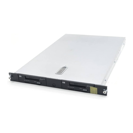
The HP StorageWorks 1U Rackmount Tape Enclosure is a rack-mountable storage system capable of holding up to two half-height 5.25 inch tape drives. It is compatible with HP 7000, 9000, & 10000 series, HP Rack System/E, HP AlphaServer, and other standard 19 inch racks. -
Page 10: Tape Enclosure Components
Tape enclosure components 15101 Figure 2 Tape enclosure front panel components Tape drive Expansion drive bay Power switch/LED 15356 Figure 3 Tape enclosure rear panel (USB and SCSI models shown) AC Power Connector SCSI Connector (SCSI models) SCSI ID Switch (SCSI mode Only) USB Connector (USB models) SAS Connector (SAS models) Introduction... - Page 11 15355 Figure 4 Tape enclosure internal components (SAS version shown) Tape drive Tape drive blank Power supply Fan assemblies (2) SAS Repeater Board (SAS Models only) 1U Rackmount Tape Enclosure Reference Guide...
- Page 12 Introduction...
-
Page 13: Tape Drive Installation
Tape Drive Installation A 3/16” (5mm) flat-blade screwdriver or T-15 Torx driver may be required to install a tape drive in the 1U tape enclosure. CAUTION: To avoid damaging the equipment due to electrostatic discharge, be sure to review and practice the procedures in Appendix B before handling the tape drives. - Page 14 Remove the drive blank: 1 Pull the spring-loaded button on the right mounting rail up 2 Slide the assembly forward and lift up. 15104 Figure 6 Removing drive blank Remove the mounting brackets from the tape drive blank. 15110 Figure 7 Remove the mounting brackets Tape Drive Installation...
- Page 15 Install the mounting brackets to the sides of the tape drive. 15127 Figure 8 Install the mounting brackets Install the tape drive into the enclosure 1 Position the mounting bracket keyhole slots over the mounting posts 2 Slide the drive toward the back of the enclosure 3 The spring-loaded button will automatically snap into place 15106 Figure 9...
- Page 16 Attach the following cables: 1 signal 2 power 3 SCSI ID selector switch (SCSI drives only) SCSI 15357 Figure 10 Attach cables to the drive NOTE: Fold excess cable length and secure with the clips provided in the tape enclosure. Replace the top access panel as shown.
-
Page 17: Scsi Cable Configurations
SCSI cable configurations The 1U Tape Enclosure supports operation of two tape drives on either 1 or 2 SCSI buses. Two internal 2-port SCSI cables are installed in the enclosure, so completing the drive installations just a matter of connecting the correct SCSI port according to your configuration. Two drives on one SCSI bus Use the configuration shown in Figure 13 when connecting both tape drives to the same SCSI bus. -
Page 18: One Drive Per Scsi Bus
One drive per SCSI bus Use the configuration shown in Figure 14 when connecting each drive to a separate SCSI bus. 15105 Figure 13 One drive per SCSI bus Tape drive 1 Tape drive 2 SCSI bus 1 cable, SCSI connector SCSI bus 2 cable, SCSI connector nearest terminator is used for drive 1 nearest terminator is used for drive 2... -
Page 19: Rack Installation
Rack Installation Rail mounting kit The rack rails supplied with the 1U rackmount tape enclosure can be used to install the unit in racks that have round, square, or threaded holes in the vertical mounting bars. The rails will fit racks with 23 - 34 inches (58 - 86 cm) separation between the front and rear vertical mounting bars. -
Page 20: Installing The Tape Enclosure In A Rack
Installing the tape enclosure in a rack WARNING! To reduce the risk of personal injury or equipment damage, be sure that: • The rack leveling jacks are extended to the floor • The full weight of the rack rests on the leveling jacks •... -
Page 21: Installing The Rack Rails
Slide the component rails toward the rear of the enclosure 2 until they lock into place. 15118 Figure 15 Attaching the component rails to the enclosure NOTE: To remove the component rail, pull out the spring-loaded tab on the side of the rail and slide it forward CAUTION: If you are returning the 1U Rackmount Tape Enclosure for service, be sure to remove... - Page 22 Insert the pins in front mounting plate of the outer rack rails into the previously marked holes in the front vertical mounting bars of the rack. See Figure 16. The rack rails will lock securely into place. 15116 Figure 16 Installing the rack rails in front of rack NOTE: To remove the rail for repositioning, push the spring-loaded tab...
- Page 23 NOTE: To remove the rail for repositioning, push the spring-loaded tab on the outside of the rack rail and slide rearward Rail installation in a rack is complete. Continue with ”Completing the installation” on page 26. 1U Rackmount Tape Enclosure Reference Guide...
-
Page 24: Installation In Racks With 10-32 Threaded Holes
Installation in racks with 10-32 threaded holes For installation in racks with 10-32 threaded holes in the vertical mounting bars the pins supplied on the rails must be removed. The rails will be attached with user-supplied 10-32 x.375 screws. Remove the pins and threaded plates from both ends of each outer rack rail. See Figure These pieces will not be used. - Page 25 Extend the rack rails past the rear vertical mounting bars and attach the back mounting plate of each outer rail to the rack using four 10-32 screws in the previously marked holes. See Figure 15120 Figure 20 Installing the rack rails in rear of rack Rail installation is complete.
-
Page 26: Completing The Installation
Completing the installation Extend the stabilizing feet if provided on your rack. Extend the left and right rack rails from the front of the rack. Align the rear of the component rails on the tape enclosure with the front ends of the rack rails, then slide the unit fully into the rack. - Page 27 Plug the AC power cord into the power cord connector, then into a grounded outlet. See Figure 15309 Figure 22 Connecting the power and USB cables to the tape enclosure Install the cable support clip(s) at the back of the rack rail(s) on one or both sides of the enclosure.
- Page 28 Rack Installation...
-
Page 29: A Regulatory Compliance Notices
Regulatory Compliance Notices Federal Communications Commission Notice Part 15 of the Federal Communications Commission (FCC) Rules and Regulations has established Radio Frequency (RF) emission limits to provide an interference-free radio frequency spectrum. Many electronic devices, including computers, generate RF energy incidental to their intended function and are, therefore, covered by these rules. -
Page 30: Modifications
Modifications The FCC requires the user to be notified that any changes or modifications made to this device that are not expressly approved by Hewlett-Packard Company may void the user's authority to operate the equipment. Cables Connections to this device must be made with shielded cables with metallic RFI/EMI connector hoods in order to maintain compliance with FCC Rules and Regulations. -
Page 31: European Union Notice
Cet appareil numérique de la classe B respecte toutes les exigences du Règlement sur le matériel brouilleur du Canada. European Union notice Products bearing the CE marking comply with the EMC Directive (89/336/EEC) and the Low Voltage Directive (73/23/EEC) issued by the Commission of the European Community and if this product has telecommunication functionality, the R&TTE Directive (1999/5/EC). -
Page 32: Japanese Notice
Japanese notice Japanese power cord notice Korean notices Regulatory Compliance Notices... -
Page 33: Czechoslovakian Notice
Disposal of Waste Equipment by Users in Private Household in the European Union Czechoslovakian notice Danish notice Bortskaffelse af affald fra husstande i den Europæiske Union Hvis produktet eller dets emballage er forsynet med dette symbol, angiver det, at produktet ikke må bortskaffes med andet almindeligt husholdningsaffald. I stedet er det dit ansvar at bortskaffe kasseret udstyr ved at aflevere det på... -
Page 34: English Notice
English notice Disposal of waste equipment by users in private household in the European Union This symbol on the product or on its packaging indicates that this product must not be disposed of with your other household waste. Instead, it is your responsibility to dispose of your waste equipment by handing it over to a designated collection point for recycling of waste electrical and electronic equipment. -
Page 35: French Notice
French notice Élimination des appareils mis au rebut par les ménages dans l'Union européenne Le symbole apposé sur ce produit ou sur son emballage indique que ce produit ne doit pas être jeté avec les déchets ménagers ordinaires. Il est de votre responsabilité... -
Page 36: Hungarian Notice
Hungarian notice Italian notice Smaltimento delle apparecchiature da parte di privati nel territorio dell'Unione Europea Questo simbolo presente sul prodotto o sulla sua confezione indica che il prodotto non può essere smaltito insieme ai rifiuti domestici. È responsabilità dell'utente smaltire le apparecchiature consegnandole presso un punto di raccolta designato al riciclo e allo smaltimento di apparecchiature elettriche ed elettroniche. -
Page 37: Lihuanian Notice
Para obter mais informações sobre locais que reciclam esse tipo de material, entre em contato com o escritório da HP em sua cidade, com o serviço de coleta de lixo ou com a loja em que o produto foi adquirido. -
Page 38: Slovakian Notice
Slovakian notice Slovenian notice Spanish notice Eliminación de residuos de equipos eléctricos y electrónicos por parte de usuarios particulares en la Unión Europea Este símbolo en el producto o en su envase indica que no debe eliminarse junto con los desperdicios generales de la casa. Es responsabilidad del usuario eliminar los residuos de este tipo depositándolos en un "punto limpio"... - Page 39 1U Rackmount Tape Enclosure Reference Guide...
- Page 40 Regulatory Compliance Notices...
-
Page 41: B Electrostatic Discharge
Electrostatic Discharge To prevent damage to the system, be aware of the precautions you need to follow when setting up the system or handling parts. A discharge of static electricity from a finger or other conductor may damage system boards or other static-sensitive devices. This type of damage may reduce the life expectancy of the device. - Page 42 Electrostatic Discharge...
-
Page 43: C Specifications
Specifications Table 2 HP StorageWorkds 1U Rackmount Tape Enclosure Parameter English Metric Dimensions Height 1.75 in 4.44 cm Depth 25.25 in 64.1 cm Width 19.0 in 48.3 cm Weight (1 drive installed) 20 lb 9.07 kg Input power requirements Rated input voltage... - Page 44 Specifications...
-
Page 45: Index
Index audience internal components authorized reseller, HP prerequisites capacity compatibility conventions rack stability, warning document rear panel components text symbols regulatory compliance notices related documentation disposal waste equipment for EU private households Subscriber’s choice, HP document symbols in text conventions...