HP StoreEver 1U User Manual
1u rack-mount enclosure
Hide thumbs
Also See for StoreEver 1U:
- User manual (48 pages) ,
- Quickspecs (5 pages) ,
- Product end-of-life disassembly instructions (5 pages)
Table of Contents
Quick Links
See also:
User Manual
HP StoreEver
1U Rack-mount Enclosure User Guide
This document provides installation instructions and specifications for the HP StoreEver 1U rack-mount enclosures. It is intended
for system administrators and technicians experienced with installing tape drives and other hardware into a rack.
*606410-007*
HP Part Number: 606410-007
Published: September 2013
Edition: Fourth
Table of Contents

Related Manuals for HP StoreEver 1U


Summary of Contents for HP StoreEver 1U
- Page 1 HP StoreEver 1U Rack-mount Enclosure User Guide This document provides installation instructions and specifications for the HP StoreEver 1U rack-mount enclosures. It is intended for system administrators and technicians experienced with installing tape drives and other hardware into a rack.
- Page 2 © Copyright 2005, 2013 Hewlett-Packard Development Company, L.P. The information contained herein is subject to change without notice. The only warranties for HP products and services are set forth in the express warranty statements accompanying such products and services. Nothing herein should be construed as constituting an additional warranty. HP shall not be liable for technical or editorial errors or omissions contained herein.
-
Page 3: Table Of Contents
Installing the Component Rails.....................14 Installing the Rack Rails.......................14 Installation in Racks with Round or Square Holes...............14 Installation in Racks with 10-32 Threaded Holes..............15 Completing the Installation....................17 4 Support and Other Resources..............19 Contacting HP........................19 Subscription Service......................19 Related information.........................19 Websites..........................19 Typographic conventions......................19 Customer self repair........................20 5 Documentation feedback................21... -
Page 4: Introduction
LTO-5 or LTO-6 tape drives unless these cables are verified for 6 Gb/s data rates. For optimum performance, only use HP cables of the length specified as qualified for your products. Refer to http://www.hp.com/storage/SPOCK... -
Page 5: Hardware Options
Power for all DDS, LTO-5, and LTO–6 tape drives is supplied through the SAS cable. For all earlier models of LTO tape drive, plug the power cable directly into the drive. Hardware Options For a list of currently supported hardware options, such as tape drives and media, visit the HP website at: http://www.hp.com/go/tape. Hardware Options... -
Page 6: Rack-Mount Enclosure Components
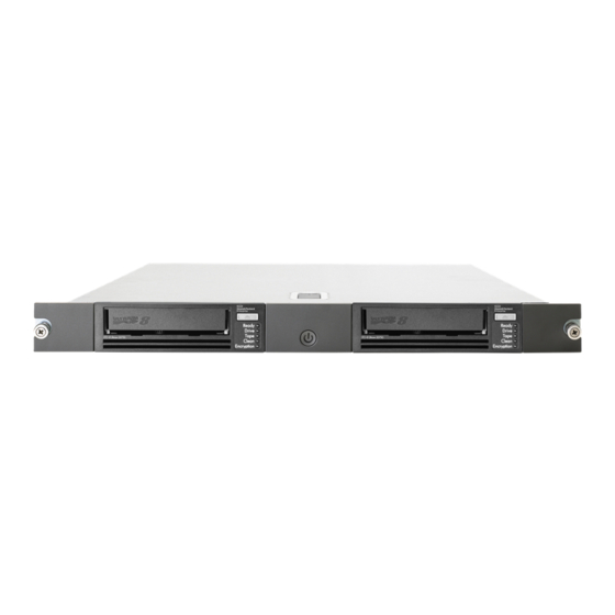
1U Rack-mount Enclosure Components Front Panel Components Figure 4 1U rack-mount enclosure front panel components 1. Drive bay 2. Expansion drive bay 3. Power switch/LED Rear Panel Components Figure 5 1U rack-mount enclosure rear panel components 1. AC Power Connector 2. -
Page 7: Internal Components (Sas Version Shown)
Internal Components (SAS version shown) Figure 6 1U rack-mount enclosure internal components (SAS version) 1. Drive 2. Drive blank 3. Power supply 4. Fan assemblies (2) 5. SAS Repeater Board (SAS Models only) 1U Rack-mount Enclosure Components... -
Page 8: Drive Installation
2 Drive Installation Tools Required A 3/16” (5mm) flat-blade screwdriver or T- 1 5 Torx driver may be required to install a drive in the 1U rack-mount enclosure. Drive Blank Removal and Installation CAUTION: To avoid damaging the equipment due to electrostatic discharge, be sure to review and practice the procedures in Electrostatic discharge before handling the drives. - Page 9 Figure 9 Removing the mounting brackets from the blank Install the mounting brackets to the sides of the drive. Always use the screws provided with the drive. Figure 10 Installing the mounting brackets on the drive CAUTION: When installing an LTO half-height tape drive, it is particularly important that you use the 6 mm M3 screws provided with the drive.
-
Page 10: Cabling With Two Devices
Figure 12 Attaching the cables 1. Power 2. Data 3. SCSI ID selector switch (SCSI drives only) NOTE: Fold excess cable length and secure with the clips provided in the enclosure. Replace the top access panel as shown. Figure 13 Replacing the access panel Cabling with Two Devices The 1U rack-mount enclosure supports operation of two devices. -
Page 11: Two Devices On One Scsi Bus
NOTE: One device per SCSI bus is the recommended configuration for LTO–3 and LTO–4 drives. Figure 14 Single-device SCSI configuration 1. Device 1 2. Device 2 3. SCSI bus 1 cable, SCSI connector nearest terminator is 4. SCSI bus 2 cable, SCSI connector nearest terminator is used for device 1 used for device 2 5. - Page 12 NOTE: Each SCSI device on the same SCSI bus must have a unique SCSI ID. Be sure that the SCSI ID is different for each device and that neither is set to SCSI ID 7, which is reserved for the SCSI controller.
-
Page 13: Rack Installation
3 1U Rack Installation Rail Mounting Kit The rack rails supplied with the 1U rack-mount enclosure can be used to install the unit in racks that have round, square, or threaded holes in the vertical mounting columns. The rails will fit racks with 23 - 34 inches (58 - 86 cm) separation between the front and rear vertical mounting columns. -
Page 14: Before You Begin
Start at the bottom of the rack, or at the top of a previously mounted component, and work upward HP recommends installing the heaviest components at the bottom and lighter ones toward the top of the rack Make sure that the rack-mounting rails are level from front to back and side to side... -
Page 15: Installation In Racks With 10-32 Threaded Holes
Insert the pins in front mounting plate of the outer rack rails into the previously marked holes in the front vertical mounting columns of the rack. The rack rails will lock securely into place. Figure 18 Inserting the pins NOTE: To remove the rail for repositioning, push the spring-loaded tab (3) on the outside of the rack rail and slide it forward (4). - Page 16 Remove the pins and threaded plates from both ends of each outer rack rail. These pieces will not be used. Figure 20 Removing the pins and threaded plates NOTE: The ends of the rack rails are marked FRONT and REAR for proper orientation. Attach the front mounting plate of each outer rail to the rack using four 10-32 screws in the previously marked holes in the front vertical mounting columns of the rack.
-
Page 17: Completing The Installation
Extend the rack rails past the rear vertical mounting columns and attach the back mounting plate of each outer rail to the rack using four 10-32 screws in the previously marked holes. Figure 22 Attaching the back mounting plate Completing the Installation Ensure all rack safety precautions stated in “Rack Safety”... - Page 18 Figure 24 Connecting the power cord (USB drive installed) Install the cable support clips at the back of the rack rails on one or both sides of the enclosure. Figure 25 Installing the cable support clips Turn on the power to the enclosure with the front panel power button. 1U Rack Installation...
-
Page 19: Support And Other Resources
Operating system type and revision level Detailed questions Subscription Service HP strongly recommends that customers register online using the Subscriber's choice web site: http://www.hp.com/go/e-updates. Subscribing to this service provides you with e-mail updates on the latest product enhancements, newest driver versions, and firmware documentation updates as well as instant access to numerous other product resources. -
Page 20: Customer Self Repair
Provides helpful hints and shortcuts. Customer self repair HP customer self repair (CSR) programs allow you to repair your HP product. If a CSR part needs replacing, HP ships the part directly to you so that you can install it at your convenience. Some parts do not qualify for CSR. -
Page 21: Documentation Feedback
5 Documentation feedback HP is committed to providing documentation that meets your needs. To help us improve the documentation, send any errors, suggestions, or comments to Documentation Feedback ([email protected]). Include the document title and part number, version number, or the URL... -
Page 22: A Specifications
A Specifications Specification S.A.E. Metric Dimensions: Height 1.7 in 4.32 cm Depth 25.3 in 64.14 cm Width 19.0 in 42.88 cm Weight (1 drive installed) 20 lb 9.07 kg Input power requirements 90 to 264 VAC 90 to 264 VAC 2.4 A 47 - 63 Hz 2.4 A 47 - 63 Hz 140 W*... -
Page 23: B Electrostatic Discharge
B Electrostatic Discharge Preventing Electrostatic Discharge To prevent damaging the system, be aware of the precautions you need to follow when setting up the system or handling parts. A discharge of static electricity from a finger or other conductor may damage system boards or other static-sensitive devices. -
Page 24: C Regulatory Information
Hewlett-Packard Company, 3000 Hanover Street, Palo Alto, California 94304, U.S. Local Representative information Russian: HP Russia: ЗАО “Хьюлетт-Паккард А.О.”, 125171, Россия, г. Москва, Ленинградское шоссе, 16А, стр.3, тел/факс: +7 (495) 797 35 00, +7 (495) 287 89 05 HP Belarus: ИООО «Хьюлетт-Паккард Бел», 220030, Беларусь, г. Минск, ул. - Page 25 HP Enterprise Servers http://www.hp.com/support/EnterpriseServers-Warranties HP Storage Products http://www.hp.com/support/Storage-Warranties HP Networking Products http://www.hp.com/support/Networking-Warranties Warranty information...