Dell PowerEdge E31S Series Owner's Manual
Hide thumbs
Also See for PowerEdge E31S Series:
- Owner's manual (164 pages) ,
- Owner's manual (164 pages) ,
- Owner's manual (121 pages)

Related Manuals for Dell PowerEdge E31S Series


Summary of Contents for Dell PowerEdge E31S Series
- Page 1 Dell PowerEdge R730 Owner's Manual Regulatory Model: E31S Series Regulatory Type: E31S001 July 2020 Rev. A05...
- Page 2 A WARNING indicates a potential for property damage, personal injury, or death. © 2017 2020 Dell Inc. or its subsidiaries. All rights reserved. Dell, EMC, and other trademarks are trademarks of Dell Inc. or its subsidiaries. Other trademarks may be trademarks of their respective owners.
-
Page 3: Table Of Contents
Contents Chapter 1: Dell PowerEdge R730 system overview.................8 Supported configurations for the PowerEdge R730 system..................8 Front panel ..................................10 3.5 inch hard drive chassis............................10 2.5 inch hard drive chassis............................12 LCD panel..................................13 Back panel....................................16 Diagnostic indicators................................. 17 Diagnostic indicators on the front panel.........................17 Hard drive indicator codes............................ - Page 4 System Setup..................................37 Viewing System Setup............................... 38 System Setup details..............................38 System BIOS.................................38 iDRAC Settings utility..............................63 Device Settings................................63 Dell Lifecycle Controller..............................64 Embedded systems management..........................64 Boot Manager..................................64 Viewing Boot Manager...............................64 Boot Manager main menu............................65 PXE boot..................................... 65 Chapter 6: Installing and removing system components.............. 66 Safety instructions................................66...
- Page 5 Removing a heat sink..............................88 Removing a processor..............................90 Installing a processor..............................93 Installing a heat sink..............................94 PCIe card holder................................97 Removing the PCIe card holder..........................97 Installing the PCIe card holder..........................98 Opening and closing the PCIe card holder latch....................99 Cable retention bracket..............................
- Page 6 Dell Embedded System Diagnostics..........................180 When to use the Embedded System Diagnostics....................180 Running the Embedded System Diagnostics from Boot Manager..............180 Running the Embedded System Diagnostics from the Dell Lifecycle Controller........180 System diagnostic controls............................181 Chapter 8: Jumpers and connectors...................182 System board jumper settings............................182...
- Page 7 Troubleshooting processors............................199 System messages................................200 Warning messages..............................200 Diagnostic messages..............................200 Alert messages................................200 Chapter 10: Getting help......................201 Contacting Dell EMC..............................201 Documentation feedback...............................201 Accessing system information by using QRL......................201 Quick Resource Locator for PowerEdge R730 and R730xd systems............202 Contents...
-
Page 8: Chapter 1: Dell Poweredge R730 System Overview
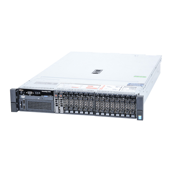
Dell PowerEdge R730 system overview The Dell PowerEdge R730 systems are rack servers that support up to two Intel Xeon E5-2600 v3 or Xeon E5-2600 v4 processors, up to 24 DIMMs, and 16 hard drives or solid state drives (SSDs). - Page 9 Figure 1. Supported configurations for the PowerEdge R730 system Dell PowerEdge R730 system overview...
-
Page 10: Front Panel
Enables you to locate a particular system within a rack. The identification buttons are located on the front and back panels. Press the system identification button to turn the system ID on or off. NOTE: Dell PowerEdge R730 system overview... - Page 11 For more information, see the Integrated Dell Remote Access Controller User’s Guide at Dell.com/idracmanuals. Dell PowerEdge R730 system overview...
-
Page 12: Inch Hard Drive Chassis
ID button (for more than five seconds) to enter BIOS progress mode. ● To reset the iDRAC (if not disabled in F2 iDRAC setup) press and hold the button (for more than 15 seconds). Dell PowerEdge R730 system overview... -
Page 13: Lcd Panel
The LCD panel of your system provides system information, status, and error messages to indicate if the system is functioning correctly or if the system needs attention. For more information about error messages, see the Dell Event and Error Messages Reference Guide at Dell.com/openmanagemanuals >OpenManage software. - Page 14 Select the Home icon. d. On the Home screen, press the Select button to enter the main menu. Related references LCD panel on page 13 Setup menu on page 15 View menu on page 15 Dell PowerEdge R730 system overview...
- Page 15 LCD message with an SEL entry. Select Simple to view LCD error messages in a simplified user-friendly description. For more information about error messages, see the Dell Event and Error Messages Reference Guide at Dell.com/ openmanagemanuals > OpenManage software.
-
Page 16: Back Panel
Enables you to connect a serial device to the system. Video connector Enables you to connect a VGA display to the system. USB port (2) Enables you to connect USB devices to the system. The ports are USB 3.0-compliant. Dell PowerEdge R730 system overview... -
Page 17: Diagnostic Indicators
Check the System Event Log or system messages for the specific issue. For more information ● When the system is turned on. about error messages, see the Dell Event and ● When the system is in standby. Error Messages Reference Guide at Dell.com/ ●... -
Page 18: Hard Drive Indicator Codes
If the hard drive is in the Advanced Host Controller Interface (AHCI) mode, the status indicator (on the right side) does not turn on. Table 6. Hard drive indicator codes Drive-status indicator pattern Condition Flashes green twice per second Identifying drive or preparing for removal. Drive ready for insertion or removal. Dell PowerEdge R730 system overview... -
Page 19: Usata Ssd Indicator Codes
Flashes green, amber, and turns off Predicted drive failure Flashes amber four times per second Drive failed Steady green Drive online Flashes green for three seconds, amber for three Rebuild aborted seconds, and turns off after six seconds Dell PowerEdge R730 system overview... -
Page 20: Nic Indicator Codes
AC power supply units (PSUs) have an illuminated translucent handle that serves as an indicator and DC PSUs have an LED that serves as an indicator. The indicator shows whether power is present or a power fault has occurred. Dell PowerEdge R730 system overview... - Page 21 For AC PSUs, use only PSUs with the Extended Power Performance (EPP) label on the back. NOTE: Mixing PSUs from previous generations of Dell PowerEdge servers can result in a PSU mismatch condition or failure to turn the system on. Flashing amber Indicates a problem with the PSU.
-
Page 22: Idrac Direct Led Indicator Codes
The iDRAC Direct LED indicator lights up to indicate that the port is connected and is being used as a part of the iDRAC subsystem. NOTE: The iDRAC Direct LED indicator does not turn on when the USB port is used in the USB mode. Dell PowerEdge R730 system overview... - Page 23 Indicates that the laptop is connected. Solid green for two seconds Flashing green (on for two seconds Indicates that the laptop connected is recognized. and off for two seconds) Turns off Indicates that the laptop is unplugged. Dell PowerEdge R730 system overview...
-
Page 24: Quick Sync Indicator Codes
Tag are found on the front of the system by pulling out the information tag. Alternatively, the information may be on a sticker on the chassis of the system. This information is used by Dell to route support calls to the appropriate personnel. -
Page 25: Chapter 2: Documentation Resources
This section provides information about the documentation resources for your system. To view the document that is listed in the documentation resources table: ● From the Dell EMC support site: 1. Click the documentation link that is provided in the Location column in the table. - Page 26 Methods to download firmware and drivers section in this document. Managing your system For information about systems management https://www.dell.com/poweredgemanuals software offered by Dell, see the Dell OpenManage Systems Management Overview Guide. For information about setting up, using, and www.dell.com/openmanagemanuals >...
-
Page 27: Chapter 3: Technical Specifications
Technical specifications The technical and environmental specifications of your system are outlined in this section. Topics: • Chassis dimensions • Chassis weight • Processor specifications • PSU specifications • System battery specifications • Expansion bus specifications • Memory specifications • Drive specifications •... -
Page 28: Chassis Weight
Table 15. Dimensions of the Dell PowerEdge R730 system Za (with Za (without bezel) bezel) 482.4 mm 444.0 mm 87.3 mm 32.0 mm 18.0 mm 684.0 mm 723.0 mm Chassis weight This section describes the weight of the system. Table 16. Chassis weight... -
Page 29: Memory Specifications
Table 18. Expansion card riser specifications Expansion card riser PCIe slots on the riser Height Length Link Riser 1 Slot 1 half-height low-profile Riser 1 Slot 2 half-height low-profile Riser 1 Slot 3 half-height low-profile Riser 2 Slot 4 full-height full-length Riser 2 Slot 5... -
Page 30: Ports And Connectors Specifications
Ports and connectors specifications USB ports The PowerEdge R730 system supports: ● USB 2.0-compliant ports on the front panel ● USB 3.0-compliant ports on the back panel ● internal USB 3.0-compliant port The following table provides more information about the USB specifications: Table 21. -
Page 31: Environmental Specifications
1280x1024 60,75 8, 16, 32 1440x900 8, 16, 32 Environmental specifications NOTE: For additional information about environmental measurements for specific system configurations, see Dell.com/ environmental_datasheets. Table 23. Temperature specifications Temperature Specifications Storage –40°C to 65°C (–40°F to 149°F) Continuous operation (for altitude less than 950 m or 10°C to 35°C (50°F to 95°F) with no direct sunlight on the... -
Page 32: Particulate And Gaseous Contamination Specifications
Table 28. Operating temperature de-rating specifications Operating temperature de-rating Specifications Up to 35°C (95°F) Maximum temperature is reduced by 1°C/300 m (1°F/547 ft) above 950 m (3,117 ft). 35°C to 40°C (95°F to 104°F) Maximum temperature is reduced by 1°C/175 m (1°F/319 ft) above 950 m (3,117 ft). -
Page 33: Expanded Operating Temperature
● 160 W or higher wattage processor is not supported. ● Redundant power supply units are required. ● Non-Dell qualified peripheral cards and/or peripheral cards greater than 25 W are not supported. ● The 3.5-inch hard drive chassis supports a maximum of 120 W processor. -
Page 34: Chapter 4: Initial System Setup And Configuration
The Integrated Dell Remote Access Controller (iDRAC) is designed to make system administrators more productive and improve the overall availability of Dell EMC systems. iDRAC alerts administrators to system issues, helps them perform remote system management, and reduces the need for physical access to the system. -
Page 35: Options To Install The Operating System
NOTE: You must have iDRAC credentials to log in to iDRAC. For more information about logging in to iDRAC and iDRAC licenses, see the latest Integrated Dell Remote Access Controller User's Guide at Dell.com/idracmanuals. Options to install the operating system... - Page 36 Downloading the drivers and firmware Dell EMC recommends that you download and install the latest BIOS, drivers, and systems management firmware on your system. Prerequisites Ensure that you clear the web browser cache before downloading the drivers and firmware. Steps 1.
-
Page 37: Chapter 5: Pre-Operating System Management Applications
Options to manage the pre-operating system applications Your system has the following options to manage the pre-operating system applications: ● System Setup ● Boot Manager ● Dell Lifecycle Controller ● Preboot Execution Environment (PXE) Related concepts System Setup on page 37... -
Page 38: Viewing System Setup
The iDRAC settings utility is an interface to set up and configure the iDRAC parameters by using UEFI (Unified Extensible Firmware Interface). You can enable or disable various iDRAC parameters by using the iDRAC settings utility. For more information about this utility, see Integrated Dell Remote Access Controller User’s Guide at Dell.com/idracmanuals. - Page 39 Integrated Devices on page 55 Serial Communication on page 58 System Profile Settings on page 59 Miscellaneous Settings on page 61 iDRAC Settings utility on page 63 Device Settings on page 63 Related tasks Viewing System BIOS on page 39 Viewing System BIOS To view the System BIOS screen, perform the following steps: Steps...
- Page 40 Option Description System Security Specifies options to configure the system security settings, such as system password, setup password, Trusted Platform Module (TPM) security. It also manages the power and NMI buttons on the system. Miscellaneous Specifies options to change the system date, time, and so on. Settings Related references System BIOS...
- Page 41 Boot Settings details About this task The Boot Settings screen details are explained as follows: Option Description Boot Mode Enables you to set the boot mode of the system. CAUTION: Switching the boot mode may prevent the system from booting if the operating system is not installed in the same boot mode.
- Page 42 ● Operating systems must be UEFI-compatible to be installed from the UEFI boot mode. DOS and 32-bit operating systems do not support UEFI and can only be installed from the BIOS boot mode. ● For the latest information about supported operating systems, go to Dell.com/ossupport. Related references...
- Page 43 Viewing Network Settings To view the Network Settings screen, perform the following steps: Steps 1. Turn on, or restart your system. 2. Press F2 immediately after you see the following message: F2 = System Setup NOTE: If your operating system begins to load before you press F2, wait for the system to finish booting, and then restart your system and try again.
- Page 44 Viewing UEFI iSCSI Settings To view the UEFI iSCSI Settings screen, perform the following steps: Steps 1. Turn on, or restart your system. 2. Press F2 immediately after you see the following message: F2 = System Setup NOTE: If your operating system begins to load before you press F2, wait for the system to finish booting, and then restart your system and try again.
- Page 45 2. Press F2 immediately after you see the following message: F2 = System Setup NOTE: If your operating system begins to load before you press F2, wait for the system to finish booting, and then restart your system and try again. 3.
- Page 46 Option Description UEFI Variable Provides varying degrees of securing UEFI variables. When set to Standard (the default), UEFI variables Access are accessible in the operating system per the UEFI specification. When set to Controlled, selected UEFI variables are protected in the environment and new UEFI boot entries are forced to be at the end of the current boot order.
- Page 47 Using your system password to secure your system About this task If you have assigned a setup password, the system accepts your setup password as an alternate system password. Steps 1. Turn on or reboot your system. 2. Type the system password and press Enter. Next steps When Password Status is set to Locked, type the system password and press Enter when prompted at reboot.
- Page 48 ● You cannot disable or change an existing system password. NOTE: You can use the password status option with the setup password option to protect the system password from unauthorized changes. Related references System Security on page 44 System Information You can use the System Information screen to view system properties such as Service Tag, system model name, and the BIOS version.
- Page 49 Option Description System Service Specifies the system Service Tag. System Specifies the name of the system manufacturer. Manufacturer System Specifies the contact information of the system manufacturer. Manufacturer Contact Information System CPLD Specifies the current version of the system complex programmable logic device (CPLD) firmware. Version UEFI Compliance Specifies the UEFI compliance level of the system firmware.
- Page 50 Specifies the memory operating mode. The options available are Optimizer Mode, Advanced ECC Operating Mode Mode, Mirror Mode, Spare Mode, Spare with Advanced ECC Mode, Dell Fault Resilient Mode and Dell NUMA Fault Resilient Mode. This option is set to Optimizer Mode by default.
- Page 51 Viewing Processor Settings To view the Processor Settings screen, perform the following steps: Steps 1. Turn on, or restart your system. 2. Press F2 immediately after you see the following message: F2 = System Setup NOTE: If your operating system begins to load before you press F2, wait for the system to finish booting, and then restart your system and try again.
- Page 52 This option is only available on certain stock keeping units (SKUs) of the processors. X2Apic Mode Enables or disables the X2Apic mode. Dell Controlled Controls the turbo engagement. Enable this option only when System Profile is set to Performance. Turbo NOTE: Depending on the number of installed CPUs, there may be up to four processor listings.
- Page 53 Viewing SATA Settings To view the SATA Settings screen, perform the following steps: Steps 1. Turn on, or restart your system. 2. Press F2 immediately after you see the following message: F2 = System Setup NOTE: If your operating system begins to load before you press F2, wait for the system to finish booting, and then restart your system and try again.
- Page 54 Option Description Port C Sets the drive type of the selected device. For Embedded SATA settings in ATA mode, set this field to Auto to enable BIOS support. Set it to OFF to turn off BIOS support. For AHCI or RAID mode, BIOS support is always enabled. Option Description Model...
- Page 55 Option Description Port H Sets the drive type of the selected device. For Embedded SATA settings in ATA mode, set this field to Auto to enable BIOS support. Set it to OFF to turn off BIOS support. For AHCI or RAID mode, BIOS support is always enabled. Option Description Model...
- Page 56 Viewing Integrated Devices To view the Integrated Devices screen, perform the following steps: Steps 1. Turn on, or restart your system. 2. Press F2 immediately after you see the following message: F2 = System Setup NOTE: If your operating system begins to load before you press F2, wait for the system to finish booting, and then restart your system and try again.
- Page 57 Option Description Embedded Video Enables or disables the Embedded Video Controller option. This option is set to Enabled by default. Controller Current State of Displays the current state of the embedded video controller. The Current State of Embedded Video Embedded Video Controller option is a read-only field.
- Page 58 Option Description Slot 7 Bifurcation Controls the bifurcation of PCIe cards installed in the specified slot. NOTE: This slot bifurcation is supported only in seven slot systems. ● When set to default, the slot operates at the default bifurcation for that slot. ●...
- Page 59 Option Description Serial Selects serial communication devices (Serial Device 1 and Serial Device 2) in BIOS. BIOS console Communication redirection can also be enabled and the port address can be specified. This option is set to Auto by default. Serial Port Enables you to set the port address for serial devices.
- Page 60 You can only change the rest of the options if the mode is set to Custom. This option is set to Performance Per Watt Optimized (DAPC) by default. DAPC is Dell Active Power Controller.
- Page 61 Option Description Memory Patrol Sets the memory patrol scrub frequency. This option is set to Standard by default. Scrub Memory Refresh Sets the memory refresh rate to either 1x or 2x. This option is set to 1x by default. Rate Uncore Enables you to select the Processor Uncore Frequency option.
- Page 62 2. Press F2 immediately after you see the following message: F2 = System Setup NOTE: If your operating system begins to load before you press F2, wait for the system to finish booting, and then restart your system and try again. 3.
-
Page 63: Idrac Settings Utility
NOTE: Accessing some of the features on the iDRAC settings utility needs the iDRAC Enterprise License upgrade. For more information about using iDRAC, see Dell Integrated Dell Remote Access Controller User's Guide at Dell.com/ idracmanuals. -
Page 64: Dell Lifecycle Controller
Dell Lifecycle Controller Dell Lifecycle Controller (LC) provides advanced embedded system management capabilities including system deployment, configuration, update, maintenance, and diagnosis. LC is delivered as part of the iDRAC out-of-band solution and Dell EMC system embedded Unified Extensible Firmware Interface (UEFI) applications. -
Page 65: Boot Manager Main Menu
Launch System Enables you to access System Setup. Setup Launch Lifecycle Exits the Boot Manager and invokes the Dell Lifecycle Controller program. Controller System Utilities Enables you to launch System Utilities menu such as System Diagnostics and UEFI shell. Related references... -
Page 66: Chapter 6: Installing And Removing System Components
Damage due to servicing that is not authorized by Dell is not covered by your warranty. Read and follow the safety instructions that are shipped with your product. -
Page 67: Before Working Inside Your System
2. Disconnect the system from the electrical outlet and disconnect the peripherals. 3. If installed, remove the front bezel. 4. If applicable, remove the system from the rack. For more information, see the Rack Installation placemat at Dell.com/poweredgemanuals. 5. Remove the system cover. Related tasks... -
Page 68: Front Bezel (Optional)
● Tyco Electronics 58433-3 or equivalent ● Wire-stripper pliers to remove insulation from size 10 AWG solid or stranded, insulated copper wire NOTE: Use alpha wire part number 3080 or equivalent (65/30 stranding). Front bezel (optional) The front bezel is attached to the front side of the system and prevents accidents while removing the hard drive or when pressing the reset or power button. -
Page 69: Installing The Optional Front Bezel
Figure 15. Removing the optional Quick Sync front bezel a. release latch b. bezel lock c. Quick Sync bezel Installing the optional front bezel Prerequisites Follow the safety guidelines listed in the Safety instructions section. Steps 1. Locate and remove the bezel key. NOTE: The bezel key is attached to the back of the bezel. - Page 70 Figure 16. Installing the optional front bezel a. bezel lock b. front bezel Figure 17. Installing the Quick Sync bezel a. bezel lock b. Quick Sync bezel Installing and removing system components...
-
Page 71: System Cover
System cover The system cover protects the components inside the system and helps in maintaining air flow inside the system. Removing the system cover activates the intrusion switch. Removing the system cover Prerequisites 1. Follow the safety guidelines listed in the Safety instructions section. 2. -
Page 72: Installing The System Cover
Related references Safety instructions on page 66 Installing the system cover Prerequisites 1. Follow the safety guidelines listed in the Safety instructions section. 2. Follow the procedure listed in the Before working inside your system section. 3. Ensure that all internal cables are connected and placed out of the way, and no tools or extra parts are left inside the system. -
Page 73: Inside The System
Damage due to servicing that is not authorized by Dell is not covered by your warranty. Read and follow the safety instructions that are shipped with your product. -
Page 74: Cooling Shroud
Damage due to servicing that is not authorized by Dell is not covered by your warranty. Read and follow the safety instructions that are shipped with your product. -
Page 75: Installing The Cooling Shroud
Damage due to servicing that is not authorized by Dell is not covered by your warranty. Read and follow the safety instructions that are shipped with your product. -
Page 76: Removing A Cooling Fan
Damage due to servicing that is not authorized by Dell is not covered by your warranty. Read and follow the safety instructions that are shipped with your product. -
Page 77: Installing A Cooling Fan
Damage due to servicing that is not authorized by Dell is not covered by your warranty. Read and follow the safety instructions that are shipped with your product. -
Page 78: Installing The Cooling Fan Assembly
Damage due to servicing that is not authorized by Dell is not covered by your warranty. Read and follow the safety instructions that are shipped with your product. -
Page 79: System Memory
CAUTION: Ensure that the cables are correctly installed and retained by the cable retention bracket before installing the cooling fan assembly. Incorrectly installed cables may get damaged. Steps 1. Align the slots on the cooling fan assembly with the guide pins on the chassis. 2. - Page 80 Memory bus operating frequency can be 1866 MT/s, 2133 MT/s, or 2400 MT/s depending on the following factors: ● DIMM type (RDIMM or LRDIMM) ● Number of DIMMs populated per channel ● System profile selected (for example, Performance Optimized, Custom, or Dense Configuration Optimized) ●...
-
Page 81: General Memory Module Installation Guidelines
Table 36. Memory population DIMM Type DIMMs Operating Frequency Maximum DIMM Rank/ Populated/ Voltage (in MT/s) Channel Channel RDIMM 2400, 2133, 1866 Dual rank or single rank 1.2 V 2400, 2133, 1866 Dual rank or single rank 1866 Dual rank or single rank LRDIMM 2400, 2133, 1866 Quad rank... -
Page 82: Sample Memory Configurations
Memory optimized independent channel mode This mode supports Single Device Data Correction (SDDC) only for memory modules that use x4 device width. It does not impose any specific slot population requirements. Memory sparing NOTE: To use memory sparing, this feature must be enabled in System Setup. In this mode, one rank per channel is reserved as a spare. - Page 83 Table 38. Memory configurations—single processor (continued) System DIMM size Number of DIMM rank, organization, and DIMM slot population capacity— —in GB DIMMs frequency in GB 1 R , x8, 2400 MT/s A1, A2 1 R, x8, 2133 MT/s 1 R, x8, 2400 MT/s A1, A2, A3, A4, A5, A6 1 R, x8, 2133 MT/s 1 R, x8, 1866 MT/s...
- Page 84 Table 39. Memory configurations—2 processors (continued) System DIMM size Number of DIMM rank, organization, and DIMM slot population capacity— —in GB DIMMs frequency in GB 1 R, x8, 2133 MT/s 1 R, x8, 2400 MT/s A1, A2, A3, A4, A5, A6, A7, A8, B1, B2, B3, B4, B5, B6, B7, B8 1 R, x8, 2133 MT/s 1 R, x8, 2400 MT/s...
-
Page 85: Removing Memory Modules
Damage due to servicing that is not authorized by Dell is not covered by your warranty. Read and follow the safety instructions that are shipped with your product. -
Page 86: Installing Memory Modules
Figure 27. Removing the memory module a. memory module b. memory module socket c. memory module socket ejector (2) Next steps 1. Install the memory module. NOTE: If you are removing the memory module permanently, install a memory module blank. 2. - Page 87 Damage due to servicing that is not authorized by Dell is not covered by your warranty. Read and follow the safety instructions that are shipped with your product. 1. Follow the safety guidelines listed in the Safety instructions section.
-
Page 88: Processors And Heat Sinks
The system should have already changed the value to reflect the installed memory. 5. If the value is incorrect, one or more of the memory modules may not be installed properly. Ensure that the memory module is firmly seated in the memory module socket. 6. - Page 89 Figure 29. Removing a heat sink 1. retention screw (4) 2. heat sink 3. processor shield 4. retention screw slot (4) Figure 30. Removing a 165 W heat sink 1. heat sink 2. retention screw (4) 3. processor socket 4. retention screw slot (4) Next steps 1.
-
Page 90: Removing A Processor
Damage due to servicing that is not authorized by Dell is not covered by your warranty. Read and follow the safety instructions that are shipped with your product. - Page 91 Figure 31. Processor shield 1. close first socket release lever 2. lock icon 3. processor 4. open first socket release lever 5. unlock icon Installing and removing system components...
- Page 92 Figure 32. Removing a processor 1. close first socket-release lever 2. pin-1 indicator of processor 3. processor 4. slot (4) 5. processor shield 6. open first socket-release lever 7. socket 8. socket keys (4) Next steps 1. Replace the processor(s). 2.
-
Page 93: Installing A Processor
Damage due to servicing that is not authorized by Dell is not covered by your warranty. Read and follow the safety instructions that are shipped with your product. -
Page 94: Installing A Heat Sink
Damage due to servicing that is not authorized by Dell is not covered by your warranty. Read and follow the safety instructions that are shipped with your product. - Page 95 3. Remove the cooling shroud. 4. Install the processor. 5. Keep the Phillips #2 screwdriver ready. Steps 1. If you are using an existing heat sink, remove the thermal grease from the heat sink by using a clean lint-free cloth. 2.
- Page 96 Figure 35. Installing the heat sink 1. retention screw (4) 2. heat sink 3. processor shield 4. retention screw slot (4) Figure 36. Installing the 165 W heat sink 1. heat sink 2. retention screw (4) 3. processor shield 4. retention screw slot (4) Next steps 1.
-
Page 97: Pcie Card Holder
Damage due to servicing that is not authorized by Dell is not covered by your warranty. Read and follow the safety instructions that are shipped with your product. -
Page 98: Installing The Pcie Card Holder
Damage due to servicing that is not authorized by Dell is not covered by your warranty. Read and follow the safety instructions that are shipped with your product. -
Page 99: Opening And Closing The Pcie Card Holder Latch
Damage due to servicing that is not authorized by Dell is not covered by your warranty. Read and follow the safety instructions that are shipped with your product. -
Page 100: Cable Retention Bracket
Damage due to servicing that is not authorized by Dell is not covered by your warranty. Read and follow the safety instructions that are shipped with your product. -
Page 101: Installing The Cable Retention Bracket
Damage due to servicing that is not authorized by Dell is not covered by your warranty. Read and follow the safety instructions that are shipped with your product. -
Page 102: Integrated Storage Controller Card
Damage due to servicing that is not authorized by Dell is not covered by your warranty. Read and follow the safety instructions that are shipped with your product. - Page 103 Figure 43. Removing the integrated storage controller card 1. integrated storage controller cable 2. integrated storage controller card 3. integrated storage controller card connector on the 4. integrated storage controller card holder system board Next steps 1. Install the expansion card riser 1. 2.
-
Page 104: Installing The Integrated Storage Controller Card
Damage due to servicing that is not authorized by Dell is not covered by your warranty. Read and follow the safety instructions that are shipped with your product. -
Page 105: Expansion Cards And Expansion Card Riser
Next steps 1. Install the expansion card riser 1. 2. Install the cooling shroud. 3. Follow the procedure listed in the After working inside your system section. Related references Safety instructions on page 66 Related tasks Before working inside your system on page 67 Removing the cooling shroud on page 74... -
Page 106: Removing An Expansion Card From Expansion Card Riser 2 Or 3
Damage due to servicing that is not authorized by Dell is not covered by your warranty. Read and follow the safety instructions that are shipped with your product. - Page 107 4. If you are removing the card permanently, install a metal filler bracket over the empty expansion slot opening and close the expansion card latch. NOTE: You must install a filler bracket over an empty expansion card slot to maintain Federal Communications Commission (FCC) certification of the system.
-
Page 108: Installing An Expansion Card Into The Expansion Card Riser 2 Or 3
Damage due to servicing that is not authorized by Dell is not covered by your warranty. Read and follow the safety instructions that are shipped with your product. -
Page 109: Removing An Expansion Card From The Expansion Card Riser 1
Damage due to servicing that is not authorized by Dell is not covered by your warranty. Read and follow the safety instructions that are shipped with your product. -
Page 110: Installing An Expansion Card Into The Expansion Card Riser 1
Damage due to servicing that is not authorized by Dell is not covered by your warranty. Read and follow the safety instructions that are shipped with your product. - Page 111 Steps 1. Unpack the expansion card and prepare it for installation. For instructions, see the documentation accompanying the card. 2. Press tab A and rotate the latch clockwise. 3. Press tab B and rotate the latch down. 4. Holding the card by its edges, position the card so that the card-edge connector aligns with the expansion card connector. 5.
-
Page 112: Removing The Riser 1 Blank
Damage due to servicing that is not authorized by Dell is not covered by your warranty. Read and follow the safety instructions that are shipped with your product. -
Page 113: Installing The Riser 1 Blank
Damage due to servicing that is not authorized by Dell is not covered by your warranty. Read and follow the safety instructions that are shipped with your product. -
Page 114: Removing Expansion Card Risers
Damage due to servicing that is not authorized by Dell is not covered by your warranty. Read and follow the safety instructions that are shipped with your product. - Page 115 Figure 52. Identifying connectors on the expansion card riser 1 a. expansion card slot 1 b. expansion card slot 2 c. expansion card slot 3 Figure 53. Removing the expansion card riser 2 1. power connector (for GPU cards) 2. expansion card riser 2 3.
- Page 116 Figure 54. Identifying connectors on the expansion card riser 2 a. expansion card slot 4 b. expansion card slot 5 c. power connector (for GPU cards) Figure 55. Removing the expansion card riser 3 1. riser guide-front 2. power connector (for GPU cards) 3.
-
Page 117: Installing Expansion Card Risers
Damage due to servicing that is not authorized by Dell is not covered by your warranty. Read and follow the safety instructions that are shipped with your product. - Page 118 Figure 57. Installing the expansion card riser 1 1. expansion card riser 1 cage 2. expansion card riser 1 3. riser guide-back (right) 4. riser guide-back (left) 5. expansion card riser 1 connector 6. riser guide-front Figure 58. Installing the expansion card riser 2 1.
-
Page 119: Gpu Card Installation Guidelines
Figure 59. Installing the expansion card riser 3 1. riser guide-front 2. power connector (for GPU cards) 3. expansion card riser 3 4. riser guide-back 5. expansion card riser 3 connector Next steps 1. Install the expansion card(s) into the expansion card risers 2 or 3. 2. -
Page 120: Removing The Gpu Card
Removing the GPU card Prerequisites 1. Follow the safety guidelines listed in Safety instructions section. 2. Follow the procedure listed in the Before working inside your system section. Steps 1. Lift the expansion card latch. 2. Close the expansion card locking tabs on the cooling shroud and the risers. 3. -
Page 121: Installing A Gpu Card
Damage due to servicing that is not authorized by Dell is not covered by your warranty. Read and follow the safety instructions that are shipped with your product. -
Page 122: Idsdm
Damage due to servicing that is not authorized by Dell is not covered by your warranty. Read and follow the safety instructions that are shipped with your product. -
Page 123: Installing An Internal Sd Card
NOTE: Temporarily label each SD card with its corresponding slot number before removal. Reinstall the SD card(s) into the corresponding slots. Steps Locate the SD card slot on the internal dual SD module, and press the card to release it from the slot. Figure 62. - Page 124 Damage due to servicing that is not authorized by Dell is not covered by your warranty. Read and follow the safety instructions that are shipped with your product. NOTE: To use an SD card with your system, ensure that the Internal SD Card Port is enabled in System Setup.
-
Page 125: Removing The Optional Internal Dual Sd Module
Damage due to servicing that is not authorized by Dell is not covered by your warranty. Read and follow the safety instructions that are shipped with your product. -
Page 126: Installing The Optional Internal Dual Sd Module
Damage due to servicing that is not authorized by Dell is not covered by your warranty. Read and follow the safety instructions that are shipped with your product. -
Page 127: Network Daughter Card
Damage due to servicing that is not authorized by Dell is not covered by your warranty. Read and follow the safety instructions that are shipped with your product. -
Page 128: Installing The Network Daughter Card
Damage due to servicing that is not authorized by Dell is not covered by your warranty. Read and follow the safety instructions that are shipped with your product. -
Page 129: Internal Usb Memory Key (Optional)
Figure 66. Installing the NDC 1. captive screw socket (2) 2. connector on the system board 3. captive screw (2) 4. touch point (2) 5. network daughter card (NDC) 6. back panel slot for Ethernet connectors Next steps 1. If applicable, install the expansion card(s) in the expansion card riser 2. 2. -
Page 130: Replacing The Optional Internal Usb Memory Key
NOTE: To locate the internal USB port (INT_USB) on the system board, see the System board jumpers and connectors section. Replacing the optional internal USB memory key Prerequisites 1. Follow the safety guidelines listed in the Safety instructions section. 2. Follow the procedure listed in the Before working inside your system section. Steps 1. -
Page 131: System Battery
Damage due to servicing that is not authorized by Dell is not covered by your warranty. Read and follow the safety instructions that are shipped with your product. -
Page 132: Power Supply Units (Psu)
Figure 70. Installing the system battery a. system battery b. system battery slot Next steps 1. Install the cooling shroud. 2. Follow the procedure listed in the After working inside your system section. 3. While booting, press F2 to enter System Setup and ensure the battery is operating properly. 4. -
Page 133: Removing The Power Supply Unit Blank
Damage due to servicing that is not authorized by Dell is not covered by your warranty. Read and follow the safety instructions that are shipped with your product. -
Page 134: Installing The Power Supply Unit Blank
Damage due to servicing that is not authorized by Dell is not covered by your warranty. Read and follow the safety instructions that are shipped with your product. -
Page 135: Installing An Ac Power Supply Unit
Damage due to servicing that is not authorized by Dell is not covered by your warranty. Read and follow the safety instructions that are shipped with your product. -
Page 136: Wiring Instructions For A Dc Power Supply Unit
DC power and to safety grounds. Do not attempt connecting to DC power or installing grounds yourself. All electrical wiring must comply with applicable local or national codes and practices. Damage due to servicing that is not authorized by Dell is not covered by your warranty. Read and follow all safety instructions that came with the product. CAUTION: Wire the unit with copper only, unless otherwise specified, use only 10 American Wire Gauge (AWG) wire rated minimum 90 ºC for source and return. - Page 137 DC power and to safety grounds. Do not attempt connecting to DC power or installing grounds yourself. All electrical wiring must comply with applicable local or national codes and practices. Damage due to servicing that is not authorized by Dell is not covered by your warranty. Read and follow all safety instructions that came with the product. Steps 1.
- Page 138 DC power and to safety grounds. Do not attempt connecting to DC power or installing grounds yourself. All electrical wiring must comply with applicable local or national codes and practices. Damage due to servicing that is not authorized by Dell is not covered by your warranty. Read and follow all safety instructions that came with the product. Steps 1.
-
Page 139: Removing A Dc Power Supply Unit
Damage due to servicing that is not authorized by Dell is not covered by your warranty. Read and follow all safety instructions that came with the product. Installing and removing system components... -
Page 140: Installing A Dc Power Supply Unit
Damage due to servicing that is not authorized by Dell is not covered by your warranty. Read and follow all safety instructions that came with the product. 1. Follow the safety guidelines listed in the Safety instructions section. -
Page 141: System Board
Damage due to servicing that is not authorized by Dell is not covered by your warranty. Read and follow the safety instructions that are shipped with your product. - Page 142 installed TPM plug-in module breaks the cryptographic binding, and it cannot be re-installed or installed on another system board. 1. Follow the safety guidelines listed in the Safety instructions section. 2. Follow the procedure listed in the Before working inside your system section. 3.
- Page 143 Figure 81. Removing the system board a. release pin b. system board c. system board holder Next steps 1. Install the system board. 2. Follow the procedure listed in the After working inside your system section. Related references Safety instructions on page 66 Related tasks Before working inside your system...
-
Page 144: Installing The System Board
Damage due to servicing that is not authorized by Dell is not covered by your warranty. Read and follow the safety instructions that are shipped with your product. - Page 145 Figure 82. Installing the system board a. release pin b. system board c. system board holder Next steps 1. Install the Trusted Platform Module (TPM). For information about how to install the TPM, see the Installing the Trusted Platform Module section. For more information on the TPM, see the Trusted Platform Module section. NOTE: The TPM plug-in module is attached to the system board and cannot be removed.
- Page 146 4. Follow the procedure listed in the After working inside your system section. 5. Import your new or existing iDRAC Enterprise license. For more information, see Integrated Dell Remote Access Controller User's Guide, at Dell.com/esmmanuals. 6. Ensure that you: a.
-
Page 147: Trusted Platform Module
Damage due to servicing that is not authorized by Dell is not covered by your warranty. Read and follow the safety instructions that are shipped with your product. -
Page 148: Initializing The Tpm For Bitlocker Users
Figure 83. Installing the TPM 1. rivet slot on the system board 2. plastic rivet 3. TPM 4. TPM connector Next steps 1. Install the system board. 2. Follow the procedure listed in the After working inside your system section. Related references Safety instructions on page 66... -
Page 149: Hard Drives
Damage due to servicing that is not authorized by Dell is not covered by your warranty. Read and follow the safety instructions that came with the product. -
Page 150: Installing A 2.5-Inch Hard Drive Blank
Figure 84. Removing a 2.5-inch hard drive blank a. hard drive blank b. release button Related references Safety instructions on page 66 Related tasks Removing the optional front bezel on page 68 Installing a 2.5-inch hard drive blank Prerequisites 1. Follow the safety guidelines listed in the Safety instructions section. 2. -
Page 151: Removing A 3.5-Inch Hard Drive Blank
Damage due to servicing that is not authorized by Dell is not covered by your warranty. Read and follow the safety instructions that came with the product. -
Page 152: Removing A Hot Swappable Hard Drive Or Solid State Drive
Damage due to servicing that is not authorized by Dell is not covered by your warranty. Read and follow the safety instructions that came with the product. - Page 153 Figure 88. Removing a hot swappable hard drive or SSD a. release button b. hard drive or SSD carrier c. hard drive or SSD carrier handle Figure 89. Removing a 1.8 inch hot-swappable uSATA SSD carrier a. release button b. SSD carrier c.
-
Page 154: Installing A Hot Swappable Hard Drive Or Solid State Drive
Damage due to servicing that is not authorized by Dell is not covered by your warranty. Read and follow the safety instructions that are shipped with your product. -
Page 155: Removing A Hard Drive Or A Solid State Drive From A Hard Drive Carrier
Figure 91. Installing a 1.8 inch hot-swappable uSATA SSD carrier a. release button b. SSD carrier c. SSD carrier handle Related tasks Removing a 3.5-inch hard drive blank on page 151 Removing a 2.5-inch hard drive blank on page 149 Installing a hard drive or solid state drives into a hard drive carrier on page 156 Installing the hard drive backplane... -
Page 156: Installing A Hard Drive Or Solid State Drives Into A Hard Drive Carrier
Related video http://www.Dell.com/QRL/Server/PER730/HDD Next steps If applicable, install a hard drive into the hard drive carrier. Related tasks Removing a hot swappable hard drive or solid state drive on page 152 Installing a hot swappable hard drive or solid state drive... -
Page 157: Installing A 1.8-Inch Hard Drive Blank
Figure 94. Removing a 1.8-inch hard drive blank a. hard drive blank b. release button Next steps If applicable, install the front bezel. Related references Safety instructions on page 66 Related tasks Removing the optional front bezel on page 68 Installing the optional front bezel on page 69 Installing a 1.8-inch hard drive blank... -
Page 158: Removing A 1.8-Inch Hard Drive From A Hard Drive Carrier
Figure 95. Installing a 1.8-inch hard drive blank 1. hard drive blank Related references Safety instructions on page 66 Related tasks Removing the optional front bezel on page 68 Installing the optional front bezel on page 69 Removing a 1.8-inch hard drive from a hard drive carrier Prerequisites 1. -
Page 159: Installing A 1.8-Inch Hard Drive Into A Hard Drive Carrier
Damage due to servicing that is not authorized by Dell is not covered by your warranty. Read and follow the safety instructions that are shipped with your product. - Page 160 Damage due to servicing that is not authorized by Dell is not covered by your warranty. Read and follow the safety instructions that are shipped with your product. CAUTION: To prevent damage to the drives and backplane, remove the hard drives from the system before removing the backplane.
- Page 161 Figure 99. Cabling diagram—2.5 inch (x16) SAS/SATA backplane 1. hard drive backplane expander 2. hard drive backplane 3. backplane signal connector 1 4. system board 5. integrated storage controller card Figure 100. Removing the 2.5 inch (x8) SAS/SATA backplane 1. hard drive backplane 2.
- Page 162 3. backplane power cable 4. SAS cable (2) 5. backplane signal cable 6. mini SAS connector (2) Figure 101. Cabling diagram—2.5 inch (x8) SAS/SATA backplane (option 1) 1. hard drive backplane 2. backplane signal connector 1 3. system board 4. integrated storage controller card Installing and removing system components...
- Page 163 Figure 102. Cabling diagram—2.5 inch (x8) SAS/SATA backplane (option 2) 1. hard drive backplane 2. backplane signal connector 1 3. system board 4. SAS A connector on the system board 5. SAS B connector on the system board Installing and removing system components...
- Page 164 Figure 103. Removing the 3.5 inch (x8) SAS/SATA backplane 1. release tab (2) 2. SAS cable (2) 3. backplane signal connector 4. backplane power cable 5. mini SAS cable connector 6. hard drive backplane Installing and removing system components...
- Page 165 Figure 104. Cabling diagram—3.5 inch (x8) SAS/SATA backplane—(option 1) 1. hard drive backplane 2. backplane signal connector 1 3. system board 4. integrated storage controller card Installing and removing system components...
-
Page 166: Installing The Hard Drive Backplane
Damage due to servicing that is not authorized by Dell is not covered by your warranty. Read and follow the safety instructions that are shipped with your product. - Page 167 Steps 1. Use the hooks on the chassis as guides to align the hard drive backplane. 2. Lower the hard drive backplane until the release tabs snap into place. 3. Connect the SAS/SATA SSD data, signal, and power cable(s) to the backplane. Figure 106.
-
Page 168: Tape Backup Unit (Optional)
Damage due to servicing that is not authorized by Dell is not covered by your warranty. Read and follow the safety instructions that are shipped with your product. -
Page 169: Installing The Tape Backup Unit
Damage due to servicing that is not authorized by Dell is not covered by your warranty. Read and follow the safety instructions that are shipped with your product. -
Page 170: Optical Drive (Optional)
Damage due to servicing that is not authorized by Dell is not covered by your warranty. Read and follow the safety instructions that are shipped with your product. -
Page 171: Installing The Optical Drive
Damage due to servicing that is not authorized by Dell is not covered by your warranty. Read and follow the safety instructions that are shipped with your product. -
Page 172: Sd Vflash Card (Optional)
An SD vFlash card is a Secure Digital (SD) card that plugs into the SD vFlash card slot in the iDRAC port card. It provides persistent on-demand local storage and a custom deployment environment that enables automation of server configuration, scripts, and imaging. It emulates USB device(s). For more information, see the Integrated Dell Remote Access Controller User's Guide at Dell.com/idracmanuals. -
Page 173: Control Panel Assembly
Damage due to servicing that is not authorized by Dell is not covered by your warranty. Read and follow the safety instructions that are shipped with your product. - Page 174 2. From inside the system, push the control panel out of the chassis. 3. Remove all the cables connecting the control panel to the chassis. Figure 115. Removing the control panel—3.5 inch hard drive system 1. control panel 2. control panel board 3.
- Page 175 Figure 116. Removing the control panel—2.5 inch hard drive system 1. control panel 2. control panel board 3. control panel connector cable 4. USB connector cable 5. screw (2) 6. vFlash media connector cable 4. Locate and press the tabs on the information tag. 5.
-
Page 176: Installing The Control Panel
Damage due to servicing that is not authorized by Dell is not covered by your warranty. Read and follow the safety instructions that are shipped with your product. - Page 177 Figure 118. Installing the control panel—3.5 inch hard drive system 1. control panel 2. control panel board 3. control panel connector cable 4. USB connector cable 5. screw 6. vFlash media connector cable Installing and removing system components...
- Page 178 Figure 119. Installing the control panel—2.5 inch hard drive system 1. control panel 2. control panel board 3. control panel connector cable 4. USB connector cable 5. screw (2) 6. vFlash media connector cable Figure 120. Installing the information tag a.
- Page 179 Next steps Follow the procedure listed in the After working inside your system section. Installing and removing system components...
-
Page 180: Chapter 7: Using System Diagnostics
Using system diagnostics If you experience a problem with your system, run the system diagnostics before contacting Dell for technical assistance. The purpose of running system diagnostics is to test your system hardware without using additional equipment or risking data loss. If you are unable to fix the problem yourself, service and support personnel can use the diagnostics results to help you solve the problem. -
Page 181: System Diagnostic Controls
The ePSA Pre-boot System Assessment window is displayed, listing all devices detected in the system. The diagnostics starts executing the tests on all the detected devices. System diagnostic controls Menu Description Configuration Displays the configuration and status information of all detected devices. Results Displays the results of all tests that are run. -
Page 182: Chapter 8: Jumpers And Connectors
Jumpers and connectors Topics: • System board jumper settings • System board jumpers and connectors • Disabling forgotten password System board jumper settings For information on resetting the password jumper to disable a password, see the Disabling a forgotten password section. Table 44. -
Page 183: System Board Jumpers And Connectors
System board jumpers and connectors Figure 121. System board jumpers and connectors Table 45. System board connectors and jumpers Item Connector Description J_BP_SIG1 Backplane signal connector 1 J_PS_2 PSU 2 connector J_BP_SIG0 Backplane signal connector 0 J_BP0 Backplane power connector 0 J_SATA_CD Optical drive SATA connector J_SATA_TBU... - Page 184 Table 45. System board connectors and jumpers (continued) Item Connector Description CYC_ID System identification button J_TPM_MODULE Trusted Platform Module connector J_RISER_2AX Riser 3 connector J_RISER_1AX Riser 1 connector J_RISER_2BX Riser 2 connector J_RISER_1BX Riser 1 connector J_RISER_3AX Riser 3 connector J_QS Quick Sync bezel connector J_RISER_3BX...
-
Page 185: Disabling Forgotten Password
Disabling forgotten password The software security features of the system include a system password and a setup password. The password jumper enables or disables password features and clears any password(s) currently in use. Prerequisites Steps 1. Turn off the system, including any attached peripherals, and disconnect the system from the electrical outlet. 2. -
Page 186: Chapter 9: Troubleshooting Your System
Damage due to servicing that is not authorized by Dell is not covered by your warranty. Read and follow the safety instructions that are shipped with your product. -
Page 187: Troubleshooting The Video Subsystem
● Compare the technical specification of the system with the external device to check the compatibility. ● Check the external device functionality with some other similar system so that we are sure that the device is working fine. ● Check any other similar external device with this system so that we are sure that the system port is working fine. For any further queries contact, Global Technical Support. -
Page 188: Troubleshooting Idrac Direct - Usb Xml Configuration
182 Troubleshooting iDRAC Direct - USB XML configuration For information about USB storage device and system configuration, see Integrated Dell Remote Access Controller User's Guide www.dell.com/poweredgemanuals Steps 1. Ensure that your USB storage device is connected to the front USB Management Port, identified by icon. -
Page 189: Troubleshooting A Serial Input And Output Device
4. If the driver is installed, ensure that you are not connected to any network through WiFi or cabled ethernet, as iDRAC Direct uses a non-routable address. Next steps If all troubleshooting fails, see the Getting help section. Related references Getting help on page 201 Troubleshooting a serial input and output device... -
Page 190: Troubleshooting A Wet System
Damage due to servicing that is not authorized by Dell is not covered by your warranty. Read and follow the safety instructions that are shipped with your product. -
Page 191: Troubleshooting A Damaged System
Damage due to servicing that is not authorized by Dell is not covered by your warranty. Read and follow the safety instructions that are shipped with your product. -
Page 192: Troubleshooting Power Supply Units
Damage due to servicing that is not authorized by Dell is not covered by your warranty. Read and follow the safety instructions that are shipped with your product. -
Page 193: Troubleshooting Cooling Problems
Damage due to servicing that is not authorized by Dell is not covered by your warranty. Read and follow the safety instructions that are shipped with your product. -
Page 194: Troubleshooting System Memory
Damage due to servicing that is not authorized by Dell is not covered by your warranty. Read and follow the safety instructions that are shipped with your product. -
Page 195: Troubleshooting An Internal Usb Key
Damage due to servicing that is not authorized by Dell is not covered by your warranty. Read and follow the safety instructions that are shipped with your product. -
Page 196: Troubleshooting An Optical Drive
Damage due to servicing that is not authorized by Dell is not covered by your warranty. Read and follow the safety instructions that are shipped with your product. -
Page 197: Troubleshooting A Drive Or Ssd
2. If your system has a RAID controller and your drives are configured in a RAID array, perform the following steps: a. Restart the system and press F10 during system startup to run the Dell Lifecycle Controller, and then run the Hardware Configuration wizard to check the RAID configuration. -
Page 198: Troubleshooting A Storage Controller
Damage due to servicing that is not authorized by Dell is not covered by your warranty. Read and follow the safety instructions that are shipped with your product. -
Page 199: Troubleshooting Processors
Damage due to servicing that is not authorized by Dell is not covered by your warranty. Read and follow the safety instructions that are shipped with your product. NOTE: When troubleshooting an expansion card, you also have to see the documentation for your operating system and the expansion card. -
Page 200: System Messages
For information about the event and error messages generated by the system firmware and agents that monitor system components, go to qrl.dell.com > Look Up > Error Code, type the error code, and then click Look it up. Warning messages A warning message alerts you to a possible problem and prompts you to respond before the system continues a task. -
Page 201: Chapter 10: Getting Help
Dell EMC product catalog. Availability varies by country and product, and some services may not be available in your area. To contact Dell EMC for sales,... -
Page 202: Quick Resource Locator For Poweredge R730 And R730Xd Systems
● A direct link to Dell to contact technical assistance and sales teams Steps 1. Go to www.dell.com/qrl and navigate to your specific product or 2. Use your smartphone or tablet to scan the model-specific Quick Resource (QR) code on your system or in the Quick Resource Locator section.