Table of Contents
Quick Links
Table of Contents
Troubleshooting

Related Manuals for ABB AV3


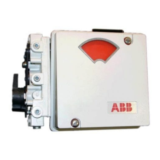
Summary of Contents for ABB AV3
- Page 1 INSTRUCTION MANUAL Characterizable Pneumatic Positioners Type AV3 and AV4 PN25058...
- Page 2 This document contains proprietary information of ABB Inc., and is issued in strict confidence. Its use, or repro- duction for use, for the reverse engineering, development or manufacture of hardware or software described herein is prohibited.
-
Page 3: Table Of Contents
SPAN ADJUSTMENT (AV3) .....................4-3 AV4 Calibration ........................4-3 ZERO ADJUSTMENT (AV4).....................4-4 SPAN ADJUSTMENT (AV4) .....................4-4 SERVO MOTOR SPEED ADJUSTMENT (AV4) ..............4-5 CALIBRATION FOR PARTICULAR APPLICATION (AV3 ONLY) ..........4-7 Zero Adjustment ........................4-7 Span Adjustment ........................4-7 GAIN AND SPEED ADJUSTMENTS ....................4-8 Gain Adjustment........................4-8 Speed Adjustment........................4-9... - Page 4 Table of Contents (continued) Page SECTION 5 - OPERATING PROCEDURES................5-1 INTRODUCTION ..........................5-1 EQUALIZING AND AIR SUPPLY SHUTOFF VALVE..............5-1 Transfer from Automatic to Manual Operation .................5-1 Transfer from Manual to Automatic Operation .................5-1 SECTION 6 - TROUBLESHOOTING...................6-1 INTRODUCTION ..........................6-1 SECTION 7 - MAINTENANCE.....................7-1 INTRODUCTION ..........................7-1 ROUTINE SERVICE........................7-1 SECTION 8 - REPAIR/REPLACEMENT PROCEDURES ............8-1...
- Page 5 CAM SELECTION .......................... C-3 CAM SHAPING METHOD......................C-5 List of Figures Title Page 1-1. Capacity Data of Type AV3/4 Positioners (Exhaust to Atmosphere) ........1-8 1-2. Air Consumption Data of Type AV3/4 Positioners ..............1-8 2-1. Type AV3/4 Positioner Operation Diagram................2-1 2-2.
- Page 6 Transferring Data from the Graph to the Cam ................. C-6 List of Tables Title Page 1-1. Reference Documents......................1-5 1-2. Type AV3/4 Nomenclature .......................1-5 1-3. Type AV 3/4 Positioner Specifications..................1-6 1-4. Optional Potentiometric Position Transmitter Specifications ............1-9 1-5. 4 to 20 mA Position Transmitter Specifications ...............1-9 1-6.
- Page 7 Cover Assembly Kit .........................9-3 9-12. Cam Follower Arm Kit ......................9-3 9-13. Type AV3 Positioner Parts List for Figures 9-1, 9-2 and 9-3............9-4 9-14. Type AV3 Reference for Cam and Manifold ................9-6 9-15. Type AV3 Reference for Output and Drive Shaft ..............9-7 9-16.
- Page 8 Read these instructions before starting installation; save these instructions for future reference. Contacting the Factory . . . Should assistance be required with any of the company’s products, contact the following: Telephone: 24-Hour Call Center 1-800-HELP-365 E-Mail: [email protected] Read First...
-
Page 9: Section 1 - Introduction
The Type AV3 positioner accepts a four to 20 milliamp current that is applied to an I/P (current to pneumatic) converter (located inside the housing) to generate an internal signal pressure. The Type AV4 positioner responds to a solid state (DDC) or contact closure input to generate a similar internal signal pressure. -
Page 10: Type Av3/4 Positioner Application
The Type AV3 positioner can be equipped with either an optional potentiometric or a four to 20 milliamp position transmitter. The Type AV4 positioner comes standard with a four to 20 milliamp position transmitter. -
Page 11: Instruction Content
Introduction Provides a description of this instruction book; its sections and uses, along with a brief description of the Type AV3 and Type AV4 positioners. This section also provides product nomenclature (Table 1-2), specifications (Tables 1-3, 1-4, 1-5), instructions on how to use this document, agency approvals (Table 1-6) and posi- tioner accessories (Table 1-7). -
Page 12: How To Use This Instruction Book
INTRODUCTION the available pressure gages. Table 1-11 lists pressure regulators and Table 1-12 lists supply air filters available from ABB. Description and Describes the functional operation of the positioners. Operation Installation Provides information about installing a Type AV positioner. Calibration Provides calibration and adjustment procedures. -
Page 13: Reference Documents
Number Document Title ANSI/NFPA 70 National Electrical Code Canadian Electrical Code C-P88-21 Characterizable Positioners, Type AV1, AV2, AV3, AV4 (Specification) CSA C22.1 Process Control Equipment PN25039 Characterizable Pneumatic Positioner, Type AV1 and AV2 (Instruction book) ISA S7.3 Quality Standards for Instrument Air (Instrument Society of America) ISA S75.13-1989... -
Page 14: Specifications
INTRODUCTION SPECIFICATIONS Table provides performance specifications of the Type AV3 and Type AV4 positioners. Tables provide perfor- mance specifications for the position transmitters. Table 1-3. Type AV 3/4 Positioner Specifications Property Characteristic/Value Input Range Type AV3 4 to 20 mA DC (30 VDC maximum) - Page 15 0.05%/1.0 psi for ±5 psi change Capacity (max. capacity, See Figure 1-1. exhausting to atmosphere) Air Consumption See Figure 1-2. Positioner Weight Type AV3 2.27 kg (5 lbs) Type AV4 2.35 kg (5 lbs 3 oz) Temperature Limits Operating -20° to 60°C (-4° to 140°F) Storage -20°...
-
Page 16: Capacity Data Of Type Av3/4 Positioners (Exhaust To Atmosphere)
1 3 0 1 4 0 1 5 0 S U PP LY P R ES S U R E (P S I) T 00 3 36 A Figure 1-2. Air Consumption Data of Type AV3/4 Positioners SPECIFICATIONS 1 - 8... -
Page 17: Optional Potentiometric Position Transmitter Specifications
Groups A, B, C, D, when used with an approved intrinsic safety barrier. NOTES: 1. Approvals and certifications pending. The position transmitters of Type AV3/4 posi- tioners are CSA certified and FM approved in the categories listed. 2. Hazardous location approvals for use in flammable atmospheres are for ambient conditions of -25°... -
Page 18: Accessories
5400277_1). Regulator Refer to Table 1-11. Air Filters ABB recommends installing an air filter in the supply air line to prevent particles from entering the positioner, which can lead to malfunction. Refer to Table 1-12 filter part numbers. NOTE: 1. - Page 19 INTRODUCTION Table 1-10. Pressure Gages Range Legend Part Number 0 - 200 0 - 30 Instrument 5326605_4 0 - 1000 0 - 160 Supply 5326605_5 0 - 1000 0 - 160 Output 5326605_6 NOTE: 1. The optional manifold provides gage ports, one for instrument (internal input signal) and two output gages.
-
Page 20: Section 2 - Description And Operation
SECTION 2 - DESCRIPTION AND OPERATION INTRODUCTION This section describes and explains the functional and physical operation of Type AV3 and AV4 positioners. Figure diagrams operating principles of the positioners. Figure shows the placement of a Type AV positioner in a typical system. -
Page 21: Functional Operation
The internal input signal pressure determines the diaphragm force. The Type AV3/4 positioner internally generates the input signal pressure; the AV3 uses a current to pneumatic converter, the AV4 uses a voltage pulse to pneumatic converter. The con- verter in both cases consists of a servo and EMI/electronics assembly. -
Page 22: Section 3 - Installation
The outlined steps are covered in sequence in this section. After installation is complete, refer to Section 4 for calibration informa- tion. NOTES: For application in a hazardous location, refer to ABB docu- ment P-P88-001, Installing a Type AV Positioner in a Hazard- ous Location. Appendix B provides a quick start guide for the Type AV positioner. -
Page 23: Enclosure Classification
ENCLOSURE CLASSIFICATION The Type AV3 and Type AV4 positioners conform to NEMA 3R when a ½-14 NPT street elbow (Fig. 3-1) is installed into the vent hole on the housing. The elbow prevents water or other liquid from entering the enclosure. -
Page 24: External And Mounting Dimensions For The Type Av Positioner
Use the following procedure to mount the positioner. 1. Set the actuator at the zero position. Connect the adjustable linkage to the drive arm. The drive arm holes correspond to stroke MOUNTING TYPE AV3 AND AV4 POSITIONERS 3 - 3... -
Page 25: Typical Positioner Mounting Using Linkage
C O U P L IN G AV O U T P U T S H A F T T 00 80 3 A Figure 3-3. Typical Positioner Mounting Using Direct Coupling MOUNTING TYPE AV3 AND AV4 POSITIONERS 3 - 4... -
Page 26: Drive Arm Connections
Appendix C for information about cam shaping. NOTE: If application is reverse-acting, the reverse-acting cam (red radial lines) must be installed and ports 01 and 02 connec- tions must be reversed. MOUNTING TYPE AV3 AND AV4 POSITIONERS 3 - 5... -
Page 27: Positioning Cam
3. Adjust the connecting linkage so that the zero radial line on the cam intersects the center of the cam roller (Fig. 3-6). 4. Lock all linkage components in place. MOUNTING TYPE AV3 AND AV4 POSITIONERS 3 - 6... -
Page 28: Connecting Tubing To Type Av Positioner
Filtering Supply Air An outside filter is recommended for Type AV positioners for pri- mary filtration of the supply air. ABB provides supply air filters as accessories, refer to Table 1-12 for part numbers. -
Page 29: Recommended Supply Air Quality
INSTALLATION Positioners equipped with manifolds have three secondary filters as part of the unit. If the filters become clogged, they can be cleaned (by removing and reverse flushing with air or liquid) or replaced by kit number 258487_1. Refer to Section 8 for manifold filter replacement procedures. -
Page 30: Wiring Type Av Positioner
INSTALLATION 2. Connect the output ports 01 and 02 as required to provide the desired direction of rotation. Figure shows single-acting tubing examples and Figure shows a double-acting tubing example. NOTE: The tubing arrangements shown in Figures 3-8 and 3-9 are general examples and may not reflect exactly the arrange- ment required for the application. -
Page 31: Tubing Examples Of Single-Acting Actuators
INSTALLATION H A N D JAC K H A N D JAC K A LT E R N AT E P IPIN G F O R D IA PH R AG M A C TUATO R W ITH H AN D JA C K N O T ES : 1 . -
Page 32: Tubing Example Of A Double-Acting Actuator
INSTALLATION D IR E C T AC T IN G R E VER SE AC T IN G (BLAC K ) C A M (R ED ) C A M M O T IO N W IT H M O T ION W IT H IN C R E AS IN G SIG N AL IN C R E AS IN G S IG N AL N O TE : IN A N Y IN S TA L L ATIO N , D IR E C T IO N O F P IS TO N T R AV E L C A N B E R E V E R S E D B Y... -
Page 33: Section 4 - Calibration
20 milliamps to set the span. These adjust- ments are made with the supply air applied to the positioner. The Type AV3 positioner has position transmitter options that are available for feedback purposes. Refer to Appendix A for more information about the position transmitter options. -
Page 34: Zero Adjustment (Av3)
CALIBRATION ZERO ADJUSTMENT (AV3) Setting the zero requires the alignment of the zero percent radial line of the cam with the center of the cam roller. Use the following steps to adjust the zero. 1. Apply a 4 mA input signal to the positioner. The actuator should be in the closed position. -
Page 35: Span Adjustment (Av3)
C A M F O LLO W E R AR M T 00 7 71 A Figure 4-2. Cam Roller Alignment SPAN ADJUSTMENT (AV3) Setting the span normally requires the alignment of the 100 per- cent radial line of the cam with the center of the cam roller. Use the following steps to adjust the span. -
Page 36: Zero Adjustment (Av4)
CALIBRATION not move until another pulse is provided to either the raise or lower terminals. Calibrating a Type AV4 positioner consists of the following adjust- ments: Zero. • Span. • Motor speed adjustment. • The Type AV4 positioner has a four to 20 milliamp position trans- mitter that provides feedback to the controller. -
Page 37: Servo Motor Speed Adjustment (Av4)
CALIBRATION 3. Slide the span adjustment assembly in the appropriate direc- tion in order to align the 100% radial line with the center of the cam roller (toward pilot valve increases span of actuator). 4. Tighten the span adjustment screw. SERVO MOTOR SPEED ADJUSTMENT (AV4) The speed of the pulse to pneumatic (P/P) converter can be adjusted with the coarse and fine speed adjustments located on... -
Page 38: Type Av4 Positioner Motor Speed Adjustments
CALIBRATION EM I/EL EC T R O N IC S H O U SIN G SE RVO M OTO R W IR E C O N N EC T IO N F IN E C O A R SE T 00 3 17 A Figure 4-3. -
Page 39: Calibration For Particular Application (Av3 Only)
7. Check the speed adjustment by repeating Steps 3 and 4. Adjust using Step 6 if necessary. CALIBRATION FOR PARTICULAR APPLICATION (AV3 ONLY) The following positioner adjustments may be used to tailor the operation of the actuator to meet application requirements. -
Page 40: Gain And Speed Adjustments
GAIN AND SPEED ADJUSTMENTS Gain and speed adjustment information applies to both the Type AV3 and Type AV4 positioners. This is the gain of the overall posi- tioner. The factory installed gain hinge spring (0.010 inch) suits most applications. This adjustment is not a mandatory part of cali- bration. -
Page 41: Speed Adjustment
If it is necessary to reduce the speed of operation, 1.02-millimeter (0.040-inch) speed control orifices (part number 5327327_1) are available as an option from ABB. These orifices are installed directly into the output ports (01 and 02) of the positioner and have ¼-NPT ports for connecting tubing from the actuator. -
Page 42: Pilot Valve Measurement For Maximum Speed
⁄ time (Fig. 4-7). ABB suggests -turn increments. Take note of the number of turns. In total, do not exceed one full turn (clockwise) from the factory setting (Fig. 4-6). This adjustment controls the amount of air going to port 01. -
Page 43: Troubleshooting Calibration Adjustments
T 00 77 8 A Figure 4-7. Speed Adjustment Screw Locations TROUBLESHOOTING CALIBRATION ADJUSTMENTS The servo assemblies of the Type AV3/4 positioners come from the factory completely calibrated. Use the following procedures only when operating difficulties occur. The corrective action... - Page 44 CALIBRATION 2. Connect a customer supplied 0 to 207 kPa (0 to 30 psig) instrument gage to the I port. The gage allows you to monitor the pneumatic signal output. 3. Make supply air connections (172 to 1,034 kPa (25 to 150 psig)) to the S port.
-
Page 45: Type Av3 Positioner Emi/Electronics Housing
PN EU M AT IC IN P U T T 00 3 18 A Figure 4-8. Type AV3 Positioner EMI/Electronics Housing 7. Adjust the servo gain as follows: a. Apply 20 mA and observe the pressure at port I. Increase the gain by adjusting the GAIN potentiometer (clockwise), until oscillation occurs (Fig. -
Page 46: Servo Adjustments (Type Av4 Positioner)
CALIBRATION Servo Adjustments (Type AV4 Positioner) The Type AV4 positioner servo comes from the factory completely calibrated. The adjustments shown in the following procedures should only be performed when required. Section 6 outlines the criterion for the adjustments. The purpose of this procedure is to adjust the servo so that it pro- duces a 20.7 to 103 kilopascals (three to 15 pounds per square inch gage) pneumatic signal when pulsing the input. -
Page 47: Servo Adjustments (Av4)
CALIBRATION Z ER O LO C KN U T SE RVO ZE RO SC R EW M IN IM U M S TO P SC R E W M A XIM U M S TO P M A XIM U M /M IN IM U M SC R E W LO C KN U TS C A M... -
Page 48: Section 5 - Operating Procedures
SECTION 5 - OPERATING PROCEDURES INTRODUCTION This section details the equalizing valve of the optional manifold. NOTE: The following procedure applies when the positioner is equipped with a manifold assembly. EQUALIZING AND AIR SUPPLY SHUTOFF VALVE The equalizing valve supplied with the manifold assembly, allows the actuator to be manually or automatically operated. - Page 49 OPERATING PROCEDURES 2. If manual operator does not lock the actuator is position: a. The actuator must be positioned from prior knowledge of the position versus signal or the actuator may jump when transferred to automatic. b. Push the valve handle in and turn to AUTO position. 3.
-
Page 50: Section 6 - Troubleshooting
SECTION 6 - TROUBLESHOOTING INTRODUCTION This section provides the operator with information about the Type AV positioner when operating difficulties are encountered. A table listing errors, probable causes, and corrective actions allows the operator to troubleshoot a problem pertaining to the positioner. Make certain the positioner is disconnected from the supply pressure source and the signal source or is removed from WARNING... - Page 51 TROUBLESHOOTING Table 6-1. Positioner Errors (continued) Error Probable Cause Corrective Action Actuator at one end of Pneumatic signal leak. Check signal at I port. If pressure is between stroke and does not 20 to 103 kPa (3 to 15 psig) and does respond respond to input change to input signal change then problem exists elsewhere.
-
Page 52: Section 7 - Maintenance
SECTION 7 - MAINTENANCE INTRODUCTION Procedures for maintenance are covered in this section. By follow- ing these procedures and time frames, reliable and troublefree operation is greatly increased. ROUTINE SERVICE Permit only qualified personnel to maintain the system. Maintenance personnel must secure the system prior to starting maintenance procedures. -
Page 53: Section 8 - Repair/Replacement Procedures
SECTION 8 - REPAIR/REPLACEMENT PROCEDURES INTRODUCTION This section provides the operator with procedures which detail removal and replacement of positioner components. Make certain the positioner is disconnected from the supply pressure source and the signal source or is removed from WARNING service before attempting any repair or replacement proce- dures. -
Page 54: Manifold
REPAIR/REPLACEMENT PROCEDURES 3. Clean or replace the filters. a. To clean the filters, soak them in a low residue solvent. After soaking, spray the filters thoroughly using compressed air until they are free of particles and solvent. b. Insert the clean or new filters (kit number 258487_1) into the filter wells. -
Page 55: Manifold (Rear View) Showing O-Rings
REPAIR/REPLACEMENT PROCEDURES 4. Lift the manifold off the positioner. 5. Before replacing the manifold, make sure there are no deposits on the bosses of the positioner or on the back of the manifold. If there is, remove the deposits. 6. Replace the O-rings or clean them if they are in good condition (Fig. -
Page 56: Gain Hinge Spring
REPAIR/REPLACEMENT PROCEDURES GAIN HINGE SPRING (Item numbers reference Figures through 9-6.) Tools required Flat-tip screwdriver ⁄ -inch Allen wrench 1. Transfer the positioner from automatic to manual operation (refer Section 2. Remove positioner cover by removing two cover screws. 3. Remove plug (item 29) from positioner housing. (Access to the hinge screws is provided through this opening.) 4. -
Page 57: Servo Assembly And Electronics Circuit Board
1. Transfer the positioner from automatic to manual operation (refer Section 2. Remove positioner cover by removing two cover screws. 3. Remove the two (AV3) or three (AV4) wires that connect the servo and EMI/electronics housing assembly to terminal block (item 59). -
Page 58: Servo And Emi/Electronics Assembly
REPAIR/REPLACEMENT PROCEDURES 6. Remove the tubing (coming from the regulator) from the bottom of the rear tee connector on the servo assembly (Fig. 8-4). M O U N T IN G SC R E W S SE RVO M O TO R L EAD R E AR T EE C O N N EC TO R (BE H IN D BE LLO W S,... -
Page 59: Cam
REPAIR/REPLACEMENT PROCEDURES 11. Carefully remove the circuit board from the housing. Determine which type of electronics circuit board you are replacing (AV3 or AV4) and perform the appropriate lettered step: a. AV3: Use a thin-bladed screwdriver to carefully pry the black wire connector from P1 and the red wire connector from P2 of the electronics circuit board. -
Page 60: Diaphragm Assembly
REPAIR/REPLACEMENT PROCEDURES DIAPHRAGM ASSEMBLY (Item numbers reference Figures through 9-6). Removing ⁄ Tools required -inch Allen wrench Adjustable wrench 1. Transfer the positioner from automatic to manual operation (refer Section 2. Using an Allen wrench, remove four diaphragm cover screws (item 45) and remove diaphragm cover. -
Page 61: Pilot Valve Stroke Adjustment
01 and 02. 2. Apply supply pressure. 3. Apply the maximum input signal to the positioner (20 mA for Type AV3 positioner or a voltage pulse to the raise terminal for Type AV4 positioner). PILOT VALVE STROKE ADJUSTMENT... -
Page 62: Stroke Adjustment Screw Locations
T 00 7 77 A Figure 8-6. Pilot Valve Measurement for Maximum Speed 5. Apply the minimum input span to the positioner (4 mA for Type AV3 positioner or a voltage pulse to the lower terminal for Type AV4 positioner). ⁄... -
Page 63: Section 9 - Support Services
Additional spare parts This is a list of parts that can be ordered for replacement. Positioner illustrations These illustrations point out all major components of the Type AV3 and Type AV4 positioners. A parts list is included along with part num- bers. -
Page 64: Additional Spare Parts Kits
SUPPORT SERVICES Table 9-3. Filter Replacements Kit No. 258484_1 (Positioners equipped with optional manifold) Part Number Quantity Description 5400057_1 Filters 5311428_1 O-rings 19984_1 O-ring lubricant Table 9-4. Shutoff Valve Kit No. 258270_1 (Positioners equipped with optional manifold) Part Number Quantity Description 5400060_1 Shutoff valve... -
Page 65: Servo Assemblies
SUPPORT SERVICES Table 9-8. Servo Assemblies Part Number Description Quantity Application 6639300_1 Servo assembly 6639300_2 Servo assembly Table 9-9. Electronics Board Assemblies Part Number Description Quantity Application 6639917_1 I/P receiver assembly 6639473_1 I/P converter assembly Table 9-10. Potentiometric Position Transmitter Part Number Quantity Description... - Page 66 SUPPORT SERVICES Table 9-13. Type AV3 Positioner Parts List for Figures 9-1, Item Part No. Description Item Part No. Description 5400253_2 Housing NIDHA13005 Indicator screw 5400258_1 Cover assembly NIDHA15012 Pilot valve screw (2 req.) 5400259_1 Valve stem NBMHA13006 Diaphragm support screw...
-
Page 67: Type Av3 Positioner (Interior, Wiring, And Tubing Details)
W IR IN G A N D T U BIN G D ETA IL 56 49 VIE W W ITH C OVE R R EM OV ED T 02 0 07 A Figure 9-1. Type AV3 Positioner (Interior, Wiring, and Tubing Details) ADDITIONAL SPARE PARTS KITS 9 - 5... -
Page 68: Type Av3 Positioner (Exploded View)
SUPPORT SERVICES T 02 0 08 A Figure 9-2. Type AV3 Positioner (Exploded View) Table 9-14. Type AV3 Reference Table for Cam and Manifold Item Type 64, 65 66, 67 AV331 5400289_1,2 11 req. 2 req. AV332 5400281_1,2 11 req. -
Page 69: Type Av3 Positioner (Front, Side And Inside Of Cover)
IN S ID E O F C OV ER S ID E V IE W T 02 0 06 A Figure 9-3. Type AV3 Positioner (Front, Side and Inside of Cover) Table 9-15. Type AV3 Reference Table for Output and Drive Shaft Item... - Page 70 SUPPORT SERVICES Table 9-16. Type AV4 Positioner Parts List for Figures 9-4, 9-5, and Item Part No. Description Item Part No. Description 5400253_2 Housing 1951041_1 Soc. head pipe plug 5400258_1 Cover assembly NIDHA13005 Indicator screw 5400259_1 Valve stem NIDHA15012 Pilot valve screw (2 req.) 5400260_1 Valve body NBMHA13006...
-
Page 71: Type Av4 Positioner (Interior, Wiring, And Tubing Details)
SUPPORT SERVICES T H IS SU P PO RT BR AC K ET O N SE RVO AS SE M BLY W IR IN G A N D T U B IN G D ETA IL 56 49 VIEW W ITH C OVE R R E M OV ED T 02 0 04 A Figure 9-4. -
Page 72: Type Av4 Positioner (Front, Side And Inside Of Cover)
SUPPORT SERVICES FR O N T V IE W IN S ID E O F C OV E R S ID E V IE W T 02 0 03 A Figure 9-5. Type AV4 Positioner (Front, Side and Inside of Cover) Table 9-17. -
Page 73: Type Av4 Positioner (Exploded View)
SUPPORT SERVICES T 02 0 05 A Figure 9-6. Type AV4 Positioner (Exploded View) ADDITIONAL SPARE PARTS KITS 9 - 11... -
Page 74: Positioner Mounting Kit
SUPPORT SERVICES Table 9-18. Positioner Mounting Kit Number 5327321_12 Valve Stem Diameter: 0.375 to 0.750 inches Part Part Part Item Description Item Description Number Number 5400266_1 Positioner mounting bracket 5311690_1 Adjustable stud, 2.69 in. .250-20x.750 Socket head screw (3 req.) 5311690_2 Adjustable stud, 3.43 in. -
Page 75: Positioner Mounting Kit
AV positioner UP30, UP40 258493_1 UP50, UP60 258494_1 AC0404 258527_1 AC0608 258528_1 AC0816 258529_1 AC1016 258530_2 ABB part number pilot AC0404 258527_1 valve positioners to AV AC0608 258528_1 positioners AC0816 258529_1 AC1016 258530_1 ADDITIONAL SPARE PARTS KITS 9 - 13... -
Page 76: Appendix A - Position Transmitters
2 ). • DESCRIPTION AND OPERATION Potentiometric Position Transmitter This is available as an option for the Type AV3 positioner (order through nomenclature). The potentiometric option is not available for the Type AV4 positioner. The potentiometric position transmitter option (AV33 1 ) uses a high durability plastic film potentiometer. -
Page 77: Calibration
POSITION TRANSMITTERS CALIBRATION The following text details the calibration procedures of the position transmitter options. There are two procedures for calibration; one for the potentiometric option (AV 1 ) and another for the four to 20 milliamp option (AV 2 ). Calibrating the Potentiometric Position Transmitter The following text provides a calibration example using the potentio- metric position transmitter. -
Page 78: Potentiometric Application Example
POSITION TRANSMITTERS Direct-acting cam rotation of 0 to 100 percent produces increasing resistance between terminal block TB1-1 and TB1-2. Reverse-acting cam rotation of 0 to 100 percent produces decreasing resistance between TB1-1 and TB1-2. The resistive change of the potentiometer is approximately 9.9 ohms (nominal) per degree of cam rotation, with a total resistance of 2000 ohms (nominal). -
Page 79: Calibrate The Potentiometric Application Example
POSITION TRANSMITTERS 6. Determine the dropping resistor value which reduces the supply voltage to 10.96 VDC: 24 VDC 10.96 VDC – 2380Ω -------------------------------------------------------- - 5.48 mA Connect a 2380 ohm variable resistor in series with the power supply. A variable resistor is required to account for the 20-percent tolerance of the potentiometer. -
Page 80: Potentiometric Position Transmitter Assembly (Exploded View
POSITION TRANSMITTERS a. Remove the cam by removing the screw, flag, nut, and washer (Fig. A-3). b. Loosen the set screw on the hub of the small gear using a ⁄ -inch Allen wrench (Fig. A-3). F LAG C A M LA R G E G EA R SM ALL G E AR SE T SC R E W... -
Page 81: Calibrating The Four To 20 Ma Position Transmitter
POSITION TRANSMITTERS Tighten the set screw on the small gear hub. NOTE: If the mesh between the large and small gears is not tight, adjust the position of the potentiometer mounting bracket (Fig. A-3) so that backlash is eliminated. e. Remove the ohmmeter from TB1-1 and TB1-2. Install the cam, screw, flag, nut, and washer (Fig. - Page 82 POSITION TRANSMITTERS 3. Insert ohmmeter leads into test jacks TP1 and TP2. If the resis- tance value is between 940 and 1060 ohms, remove the ohmmeter leads and proceed to Step 4. Otherwise continue with Step 3. The pneumatic supply pressure must be turned off before removing the positioning cam.
-
Page 83: To 20 Ma Position Transmitter Assembly (Exploded View
POSITION TRANSMITTERS F LAG C A M LA R G E G EA R SM ALL G EAR SE T SC R EW M O U N T IN G BR AC K ET PO T EN T IO M E T ER ) Ω... -
Page 84: Appendix B - Quick Start
Manifold with equalizing valve Manifold without equalizing valve Position Transmitter None (Type AV3 and Type AV4) Potentiometric resistive output (Type AV3 only) 4 to 20 mA Output (Type AV3 only) Drive Shaft Standard with drive arm ½ -inch square end NOTE: 1. -
Page 85: Mounting The Positioner
QUICK START MOUNTING THE POSITIONER Install the positioner as required on the actuator. Figures show typical mounting arrangements. M O U N TIN G B R A C K E T TYP E AV P O S ITIO N E R PAN H E A D M A C H IN E S C R E W A D JU S TA B LE E L A S TIC... -
Page 86: Typical Positioner Mounting Using Driect Coupling
QUICK START RO TA RY AC TUATO R A C TUATO R SH AF T SE T SC R E W S AV ??? ??1? PO S IT IO N E R C O U PL IN G AV O U T PU T SH AF T T 00 80 3 A Figure B-2. -
Page 87: External Tubing Connections
QUICK START 4. Lock all linkage components in place. C A M C A M RO LL E R C A M F O LLO W E R AR M T 00 7 71 A Figure B-4. Cam Roller Alignmment EXTERNAL TUBING CONNECTIONS 1. -
Page 88: Calibration
A cable clip (Fig. B-9) is provided inside the positioner so entanglement can be avoided. CALIBRATION Table presents calibration procedures for Type AV3 and Type AV4 positioners in table format. Table pertains to Type AV4 and is a required part of calibration. -
Page 89: Tubing Examples Of Single-Acting Actuators
QUICK START H A N D JAC K H A N D JAC K A LT E R N AT E P IP IN G F O R D IA P H R A G M A C TUATO R W ITH H A N D JA C K N O T ES : 1 . -
Page 90: Tubing Example Of A Double-Acting Actuator
QUICK START D IR E C T AC T IN G R E VER SE AC T IN G (BLAC K ) C A M (R ED ) C A M M O T IO N W IT H M O T IO N W IT H IN C R E AS IN G SIG N AL IN C R E AS IN G SIG N AL N O TE: IN A N Y IN S TA L L ATIO N , D IR E C TIO N O F P IS TO N TR AV E L C AN B E R EV E R S ED B Y... -
Page 91: Type Av Calibration Adjustment Locations
QUICK START TB1 CONNECTIONS NOMENCLATURE – AV23 – Av33 – AV44 – T00807A Figure B-8. Type AV Wiring Connections PILOT VALV E O PT IO N AL M A N IF O L D SE RVO AS SE M B LY C O N D U IT H O LE SPA N A D JU S T M EN T A SS EM B LY... -
Page 92: Calibration Procedures
QUICK START Table B-2. Calibration Procedures Calibration Procedure Calibration Procedure Adjustment Adjustment Zero 1. Turn on supply air. Apply a 4 mA Zero 1. Turn on supply air. Pulse the posi- input signal to the positioner. The tioner in order to arrive at the mini- actuator should be in the closed posi- mum (closed) position. -
Page 93: Type Av4 Positioner Motor Speed Adjustment
QUICK START EM I/EL EC T R O N IC S H O U SIN G SE RVO M OTO R W IR E C O N N EC T IO N F IN E C O A R SE T 00 3 17 A Figure B-10. -
Page 94: Appendix C - Cam Characterization
Table lists control signal pressures of specific Type AV3 positioners which corresponds to the signal span percent values in Figures C-1, and C-3. Table... -
Page 95: Cam Characterization
CAM CHARACTERIZATION 1 0 0 L IM IT E D T R AV E L S C A LE = % O F S IG N A L R A N G E L IM IT E D S IG N A L 1 0 0 S O L ID L IN E IN D IC AT ES F O RWA R D T R AV E L (D IR E C T AC T IN G ) -
Page 96: Cam Selection
CAM CHARACTERIZATION Table C-1. Relationship of Input to Output for I/P Converter (AV3) I/P Converter I/P Converter % of Control % of Control Signal Signal Input (mA) Output (psig) Input (mA) Output (psig) 13.6 10.2 15.2 11.4 16.8 12.6 18.4 13.8... -
Page 97: Desired Control
CAM CHARACTERIZATION 2. Plot the exact control medium versus control signal characteristic given or desired for the application. This is usually a linear function (Fig. C-5). 10 0 % O F SIG N A L 1 0 0 % O F C O N TR O LLE D M ED IU M T 00 7 94 A Figure C-5. -
Page 98: Cam Shaping Method
CAM CHARACTERIZATION 10 0 % O F S IG N A L 10 0 % O F P IS TO N O R VALV E T R AV E L T 00 7 96 A Figure C-6. Cam Characteristics If the required characteristic cannot be obtained using the above procedure, or if more exact characteristics are required, alter the shape of a standard A, B, or C cam or cut a new cam from a blank cam as outlined under... -
Page 99: Transferring Data From The Graph To The Cam
Optional blank cam (part number 5400277_1) is available from ABB if alteration of the stan- dard cam is not desired. CAM SHAPING METHOD... - Page 100 Errors ................6-1 Potentiometric position transmitter ....... 9-3 Exploded view Servo assembly ............ 9-3 Type AV3 ..............9-6 Air supply quality ............3-8 Type AV4 ............9-11 AV3 calibration ............4-1 External dimensions............3-3 AV3/4 Application ............1-2 Description............1-1 Specifications............1-6 Fail in place..............1-1 AV4 calibration ............
- Page 101 Replacement procedures Kits ..............1-10 Servo assembly and electronics circuit board ..8-5 Retro-fit kits ............1-10 Replacing Type AV3 and AV4 positioners ......3-2 Diaphragm assembly ..........8-8 Gain hinge spring..........8-3 Motor control circuit board ........8-5 Pilot valve body............. 8-4 NEMA 250..............1-7...
- Page 102 Index (continued) Type AV3 ............4-11 Type AV4 ............4-14 Tubing connections ............ 3-8 Tubing example Double-acting............3-11 Single-acting ............3-10 Unpacking and inspection .......... 3-1 Vibration effect ............1-7 Voltage supply ............1-6 Weight ................ 1-7 Wiring Connections............3-9 Diagram ..............
- Page 103 The Company’s policy is one of continuous product improvement and the right is reserved to modify the information contained herein without notice. © 2002 ABB Automation Inc. Printed in USA ABB Inc. ABB Instrumentation Ltd ABB Instrumentation S.p.A ABB Automation Products GmbH Instrumentation Division Howard Road, St.