Hitachi PSC-A32MN Operation Manual
Hide thumbs
Also See for PSC-A32MN:
- Installation and operation manual (93 pages) ,
- Instruction manual (5 pages) ,
- Installation and operation manual (870 pages)

Related Manuals for Hitachi PSC-A32MN


Summary of Contents for Hitachi PSC-A32MN
- Page 1 Operation Manual - PSC-A32MN - IMPORTANT: READ AND UNDERSTAND THIS MANUAL BEFORE USING THIS CENTRAL STATION. KEEP THIS MANUAL FOR FUTURE REFERENCE. P5415644...
- Page 3 IMPORTANT NOTICE ● HITACHI pursues a policy of continuing improvement in design and performance of products. The right is therefore reserved to vary specifications without notice. ● HITACHI cannot anticipate every possible circumstance that might involve a potential hazard. ● This heat pump air conditioner is designed for standard air conditioning only. Do not use this heat pump air conditioner for other purpose such as drying clothes, refrigerating foods or for any other cooling or heating process. ● Do not install the unit in the following places. It may cause a fire, deformation, corrosion or failure. * where oil vapor or oil is dispersed (including machinery oil). * where a lot of sulfide gas drifts such as at hot spring. * where inflammable gas may be generated or flowed. * where strong salty wind blows such as coast regions. * with an atmosphere of acidity or alkalinity. ● Do not install the unit in the place where silicon gas drifts. If the silicon gas attaches to the surface of heat exchanger, the fin surface repels water. Drain water splashes outside of the drain pan and splashed water runs inside of electrical box. It may cause water leakage or electrical devices failure. ● Pay attention to the following points when the unit is installed in a hospital or other facilities where electromagnetic wave is generated by a medical equipment. * Do not install the unit in the place where the electromagnetic wave is directly radiated to the electrical box, remote control cable or remote control switch. * Install the unit at least 3 meters away from electromagnetic wave radiators such as a radio. ● Do not install the unit in the place where animals and plants are exposed to the direct blowing air from the unit. It could adversely affect the animals and plants. ● The installer and system specialist shall comply with local regulations or standards for the safety. The following standards may be applicable, if local regulations are not available. International Organization for Standardization, ISO5149 or European Standard, EN378 or Japan Standard, KHKS0010. ● No part of this manual may be reproduced without written permission. ● It is assumed that this heat pump air conditioner will be operated and serviced by English speaking people.
- Page 4 SAFETY SUMMARY < Signal Words > ● Signal words are used to identify levels of hazard seriousness. Definitions for identifying hazard levels are provided below with their respective signal words. : DANGER indicates a hazardous situation which, if not avoided, DANGER will result in death or serious injury. : WARNING indicates a hazardous situation which, if not avoided, WARNING could result in death or serious injury. : CAUTION indicates hazards or unsafe practices which could result CAUTION in minor personal injury or product or property damage. NOTICE : NOTICE is used to address practices not related to personal injury. NOTE : NOTE is useful information for operation and/or maintenance. P5415644...
-
Page 5: Table Of Contents
TABLE OF CONTENTS 1. Safety Summary ..............................1 2. System Configuration ............................2 3. Features ................................2 4. Part Names and Functions ..........................3 4.1 Part Names .............................3 4.2 Screen Display ............................4 5. Quick Reference ..............................5 5.1 Screen Structure .............................5 5.2 Functions ..............................6 6. Initial Power Activation Setting .........................7 7. Operation Procedure ............................8 7.1 Display of All Groups ..........................8 7.2 Display of Specified Block ........................9 7.3 Simultaneous Run/Stop for All Groups ....................10 7.4 Simultaneous Run/Stop for Each Block .................... - Page 6 P5415644...
-
Page 7: Safety Summary
● Do not perform installation work and electrical wiring connection by yourself. Contact your distributor or dealer of HITACHI and ask them for installation work and electrical wiring by service person. ● Do not modify the electrical wiring. It may cause serious accident. -
Page 8: System Configuration
2. System Configuration This central station (PSC-A32MN) is connected to H-LINK and used for the central control and monitoring of the air conditioners. < Example > Max. 64 Refrigerant Cycles and Max. 160 Indoor Units are available. (For H-LINK II Only) Max. 8 Units in the same H-LINK are available. H-LINK Transmission Wiring Central Station (PSC-A32MN) Wiring for Group Group Group... -
Page 9: Part Names And Functions
4. Part Names and Functions 4.1 Part Names Touch Pen To operate the touchscreen of the central station. Color LCD Display with Touchscreen Power Indicator To operate and monitor the units by the touchscreen To indicate the power condition of display. It is operated by using touch pen (accessory). the central station. The touchscreen display will automatically sleep when the OFF (lamp): Power is turned OFF touchscreen is not operated for the given length of time. ON (lamp): Power is turned ON Gesture control is not supported such as : - Tap 2 places simultaneously - Flick Operation Operation Indicator To indicate the Run/Stop condition of the units. OFF: All the units are stopped. ON (Green): One or more units are in operation. Flashing (Red): In abnormal condition NOTE: Remove the protection sheet on LCD (liquid crystal display) before using this product. P5415644... -
Page 10: Screen Display
4.2 Screen Display Block Button To change the screen display “Monitor (All Groups)” into “Block”Present Indication Unit Condition Icon indication by tapping this button. To display the present To indicate the unit condition such Group Button indication (all groups) as filter sign, demand, etc. To indicate the operating condition of each group as follows. Green: Run Gray: Stop Red: Abnormal If the target group button is tapped, “Settings” of the target group screen will be indicated. * (Refer to the item 7.5.) “Alarm Inform.” Button To indicate the abnormality Tap the button for details. “Stop all gr.” Button To stop all the units simultaneously which are controlled by the central station. “Run all gr.” Button “Menu” Button “Icon Guide” Button To run all the units simultaneously which are controlled by the central To indicate the menu items Tap this button to display an station. -
Page 11: Quick Reference
5. Quick Reference 5.1 Screen Structure The table below shows the display on the screen and its function. Screen Display Function Page To display the name of all groups Monitor (All Groups) and operating conditions To display the name of groups in the Monitor (Block) block and operating conditions To display the list of menu items Menu To reset the filter sign Filter Sign Reset To set or change the weekly schedule To copy the schedule setting Schedule Settings Schedule Timer Setting To delete the schedule timer setting To specify days of suspended Holiday Setting schedule setting Schedule Timer To set schedule operation ON/OFF ON/OFF Setting To adjust the setting temperature Setting temp. range of range of remote control the remote control To adjust the date and time Date and time Settings Display of screen for To lock the touchscreen for cleaning cleaning To calibrate the touch position on Touchscreen Calibration the touchscreen... -
Page 12: Functions
5.2 Functions The table below shows the main functions. < Operation Procedure > Display All Groups in a List (All of Air Conditioner Registered to Central Station) Display of Specified Block Simultaneous Run/Stop for All Groups Simultaneous Run/Stop for Block Run/Stop for Each Group Operation Mode Change Fan Speed Setting Swing Louvre Direction Setting Temperature Permitting/Prohibiting Operation from Remote Control Switch < Menu Function > Menu (Menu Items and Details) Menu Filter Sign Reset Schedule Operation Adjusting Setting Temperature Range of Remote Control Date and Time Settings Display of Screen for Cleaning Touchscreen Calibration Registering Groups/Blocks Name Screen Display Setting Accumulated Operation Time of Unit Contact Information Summer Time Operation P5415644... -
Page 13: Initial Power Activation Setting
6. Initial Power Activation Setting < Preparation 1 > Turn on the power supply of the air conditioners. To protect the compressor, the power supply should be turned on 12 hours before the operation is started. Do not turn off the power supply during the air conditioning seasons. < Preparation 2 > After the preparation 1 is completed, turn on the power supply of the central station. “Start-up” will be displayed for a while and the screen changes to “Monitor (All Groups)”. NOTE: Setting the date and time may be required after long-term power failure. In that case, “Set Date/Time” will be displayed on the screen. If “Set” is tapped, “Date and time settings” will be displayed. Refer to the item 8.6 for setting the date and time. P5415644... -
Page 14: Operation Procedure
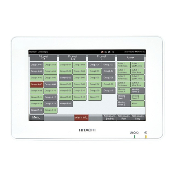
7. Operation Procedure 7.1 Display of All Groups (1)* (1) Tap “All Groups” on the touchscreen display. * The tab of marked with (1), “All Groups” will not be displayed if only 1 (one) block has been registered. (2) All groups are displayed on the touchscreen. Each operation status is indicated by color of the group button as follows: Green: Run Gray: Stop Red: Abnormal * “All Groups” screen may be different depending on the Control Pattern. The screen on the left indicates the Pattern A (4 Blocks × 8 Groups) set by the Control Pattern. NOTE: The touchscreen display will automatically sleep when the touchscreen is not operated for the given length of time. (To wake up, tap the screen.) P5415644... -
Page 15: Display Of Specified Block
7.2 Display of Specified Block(1) Select the target block from the screen of “Monitor (All Groups)” or “Monitor (Block)”. (2) The groups in the selected block will be displayed on the touchscreen. Each operation status is indicated by color of the group button as follows: Green: Run Gray: Stop Red: Abnormal * “Block” screen may be different depending on the Control Pattern. The screen on the left indicates the Pattern A (4 Blocks × 8 Groups) set by the Control Pattern. (3) Tap “Air Temp Display” to display the outside air temperature and the inlet temperature. (4) Tap “Display Condit.” to display the condition of the operation. NOTE: • The touchscreen display will automatically sleep when the touchscreen is not operated for the given length of time.(To wake up, tap the screen.) • It may take time to display the temperature. • The inlet temperature is displayed only while operating. P5415644... -
Page 16: Simultaneous Run/Stop For All Groups
7.3 Simultaneous Run/Stop for All Groups (1) Tap “All Groups” on the touchscreen display. (2) Tap “Run all gr.” when all groups run simultaneously. Tap “Stop all gr.” when all groups stop simultaneously. (3) The confirmation screen will be displayed. Tap “Yes”. (All indoor units connected to the central station will be simultaneously operated.) Tap “No” to cancel this command. NOTES: • “Run/Stop all gr.” command will not be effected to the groups specified in “Exception Setting of Run/Stop Operation”. • In case that the Ice Storage Series is connected, the Air Conditioner Unit cannot operate while the Heat Storage Unit is operating. P5415644... -
Page 17: Simultaneous Run/Stop For Each Block
7.4 Simultaneous Run/Stop for Each Block (1) Select the target block from the touchscreen display to set simultaneous Run/Stop operation. (2) Tap “Run by Block” when the selected Block runs simultaneously. Tap “Stop by Block” when the selected Block stops simultaneously. (3) The confirmation screen will be indicated. Tap “Yes”. All groups (all indoor units) in the selected block connected to the central station will be simultaneously operated. Tap “No” to cancel this command. NOTES: • “Run/Stop by Block” command will not be effected to the blocks specified in “Exception Setting of Run/Stop Operation”. • In case that the Ice Storage Series is connected, the Air Conditioner Unit cannot operate while the Heat Storage Unit is operating. P5415644... -
Page 18: Run/Stop For Each Group
7.5 Run/Stop for Each Group The mode is different depending on the setting of the Control Mode (Run/Stop Only). Control Restricted (Run/Stop Only) : Control Method when set as “Disable” Refer to the item 7.5.1. Control Restricted (Run/Stop Only) : Control Method when set as “Enable” Refer to the item 7.5.2. 7.5.1 Run/Stop for Each Group (Control Restricted (Run/Stop Only) : “Disable”) (1) Select the screen of “Monitor (AllGroups)” or “Monitor (Block)”. Select the group to set by tapping the group button. (2) Selected group setting will be indicated on the touchscreen display. Tap “ON” or “OFF”. (3) Tap “Monitor screen” to return to Monitor screen. P5415644... -
Page 19: Run/Stop Operation For Each Group (Control Mode (Run/Stop Only): "Enable")
7.5.2 Run/Stop for Each Group (Control Restricted (Run/Stop Only) : “Enable”)(1) Select the target group at screen of “Monitor (All Groups)” in “Run/Stop Only” mode. (2) The selected group operation is alternately changed by tapping as follows. “Stop” “Run” In this mode, simultaneous Run/ Stop operations for all groups is available by “Run all gr.” and “Stop all gr.” buttons. Refer to the item 7.3 for details. (1) Select the target group at screen of “Monitor (Block)” in “Run/Stop Only” mode. (2) The selected group operation is alternately changed by tapping as follows. “Stop” “Run” In this mode, simultaneous Run/Stop operations for block is available by “Run by Block” and “Stop by Block” buttons. Refer to the item 7.4 for details. NOTE: In case that the Ice Storage Series is connected, the Air Conditioner Unit cannot operate while the Heat Storage Unit is operating. P5415644... -
Page 20: Operation Mode Change
7.6 Operation Mode Change(1) Select the target group at screen of “Monitor (All Groups)” or “Monitor (Block)” to change the operation mode setting. The pop-up of “Setting” for the selected group is displayed on the touchscreen. (2) By tapping “ ” or “ ” at the Operation Mode, it will switch in order to “COOL”, “HEAT”, “DRY”, “AUTO” and “FAN”. COOL HEAT AUTO * The “AUTO” (Heating/Cooling Automatic Operation) will be included as option if applicable. (3) Tap “Monitor screen” to return to Monitor screen. NOTES: • By tapping “<” or “>” at the detailed setting screen, the operation mode will be switched to another group in the same block. Restricted (Run/Stop Only) : In case of “Enable”, each Setting Change is for all Groups or Blocks. • Control Setting Change is not possible for each Group. • Some operation mode cannot be set depending on the type of Air Conditioner Unit. Contact your dealer or go to the inquiry counter of a designated maker for detailed information. • If the settings are mixed when multiple groups are selected, the display will remain blank. -
Page 21: Fan Speed Setting
7.7 Fan Speed Setting(1) Select the target group at screen of “Monitor (All Groups)” or “Monitor (Block)” to change the fan speed setting. The pop-up of “Setting” for the selected group is displayed on the touchscreen. (2) By tapping “ ” or “ ” at the Fan Speed, it will switch in this order: “LOW”, “MEDIUM”, “HIGH”, “HIGH2”, “AUTO”. MEDIUM HIGH HIGH2 AUTO * “HIGH2” or “AUTO” may not be indicated depending on the type of the Air Conditioner. (3) Tap “Monitor screen” to return to Monitor screen. NOTES: • By tapping “<” or “>” at the detailed setting screen, the Fan Speed will be switched to another group in the same block. • Control Restricted (Run/Stop Only) : In case of “Enable”, each Setting Change is for all Groups or Blocks. Setting Change is not possible for each Group. • Actual fan speed during the dry operation will be “LOW” regardless of the fan speed setting. • The figure above shows an example of a connected Air Conditioner Unit. The Fan Speed may not be indicated in certain case. -
Page 22: Swing Louvre Direction
7.8 Swing Louvre Direction(1) Select the target group at screen of “Monitor (All Groups)” or “Monitor (Block)” to change the swing louvre direction. The pop-up of “Setting” for the selected group is displayed on the touchscreen. (2) By tapping “ “ or “ ” of the “LOUVRE”, the swing louvre direction will be changed alternately as follows. Indication AUTO COOL Auto Angle Range Swing Auto Angle Range HEAT Swing : Auto swing operation will be started. AUTO (3) Tap “Monitor screen” to return to Monitor screen. NOTES: • By tapping “<” or “>” at the detailed setting screen, the Swing Louvre Direction will be switched to another group in the same block. -
Page 23: Setting Temperature
7.9 Setting Temperature(1) Select the target group at screen of “Monitor (All Groups)” or “Monitor (Block)” to change the setting temperature. The pop-up of “Setting” for the selected group is displayed on the touchscreen. (2) By tapping “ ”, the temperature is increased by 1 C. (Max. 30 By tapping “ ”, the temperature is decreased by 1 * At Cooling, Dry, Fan and Auto operation: Min. 19 * At Heating operation: Min. 17 (3) Tap “Monitor screen” to return to Monitor screen. NOTES: • By tapping “<” or “>” at the detailed setting screen, the Setting Temperature will be switched to another group in the same block. • Control Restricted (Run/Stop Only) : In case of “Enable”, each Setting Change is for all Groups or Blocks. Setting Change is not possible for each Group. • The figure above shows an example of the setting temperature for a connected Air Conditioner Unit. The setting temperature range may not be indicated in certain case. • If the settings are mixed when multiple groups are selected, the display will remain blank. -
Page 24: Permitting/Prohibiting Operation From Remote Control Switch
7.10 Permitting/Prohibiting Operation from Remote Control Switch This function is used for prohibiting the operation from the remote control switch. When the remote control switch is set as prohibited (by Item/ All Items), the control of the selected item will not be available. The items that can be selected are : Run/Stop, Operation Mode, Fan Speed, Swing Louvre and Temperature. NOTE: Pay attention to the following when the group support prohibition by Item. • When setting “Remote control operation,” do not use the function control lock of the remote control switch. *When using at the same time, “Remote control operation” and control lock functions, “Remote control operation” is prior and the control lock function cannot be set. *When changing setting from “All prohib.” to “All permitt.” at “Remote control operation”, all the setting for the control lock of the remote control switch will be cancelled.(1) Select the target group at the screen of “Monitor (All Groups)” or “Monitor (Block)” to set the function of “RCS Operation Prohibited” setting. The pop-up of “Setting” for the selected group is displayed on the touchscreen. (2) Select “Remote control operation” by tapping. (3) Tap “Monitor screen” to return to Monitor screen. P5415644... - Page 25 NOTES: • By tapping “<” or “>” at the detailed setting screen, the remote control switch Permitted/ Prohibited will be switched to another group in the same block. • Control Prohibited (Run/Stop Only) : In case of “Enable”, each Setting Change is for all Groups or Blocks. Setting Change is not possible for each Group. • Even if remote control switch is set as “Prohibit.”, it is possible to stop operation with the remote control switch while running. It is also possible to restart operation using the remote control switch. However, the Stop operation will be only used in the case of an emergency. Do not use it in normal operation. • If “Power Supply ON/OFF” (d1, d3) is set, do not set the remote control switch as “Prohibit.”. If the remote control switch is restricted when using “Power Supply ON/OFF”, the function “Control lock” for the remote control switch shall be used. • If a communication error occurs, the remote control switch “STOP” (by item) may be cancelled. In this case, do the setting again. • Do not set the prohibiting operation if multiple centralized controllers are used in the same H-LINK. Additionally, do not set this by other centralized controller or it may cause malfunction. P5415644...
-
Page 26: Menu
8. Menu The table below shows menu item and its function. Item Function Page This function is used for turning off the filter sign of the connected indoor units. Filter Sign Reset Regardless the occurrence or not of the Filter Sign, it is possible to reset the Filter Sign time display of the Air Conditioner Unit. This function is used to Run/Stop the operation of the Air Conditioner at a Schedule Setting desired time. This function is used for setting the time (by the minute), “Run/Stop” and Schedule Timer temperature (19~30 Setting For weekly schedule setting, up to 10 schedule items can be set per day. It is also available to copy the setting contents. This function is used for suspending the schedule operation temporarily. Holiday Setting The schedule operation will be suspended when the day is set as Holiday. This function is used for setting irregular holidays such as national holidays. “Schedule Timer OFF Setting” is used for suspending the schedule operation for the target group. Schedule Timer The schedule operation will not be available when Schedule Timer is OFF. ON/OFF Setting This function is used for a long holiday, sudden holidays, national holidays, etc. Adjusting Setting This function is used for adjusting the setting temperature range. It is possible Temperature Range of to set Cooling minimum temperature or Heating maximum temperature. Remote Control Date and Time Settings This function is used for adjusting date and time. Display of Screen for This function is used for cleaning LCD (liquid crystal display) of central station. Cleaning The screen will return to “Menu” after 10 seconds of not being tapped. -
Page 27: Display Menu Screen
8.1 Display Menu Screen The setting items for the indoor unit and central station are laid out in the menu.(1) Tap “Menu” on the screen for “All Groups” or “Block”. (2) The screen of “Menu” will be displayed. (3) Select the item from the screen of “Menu”. 8.2 Exit Menu Screen Tap “Monitor screen” on the screen to return to Monitor screen. P5415644... -
Page 28: Filter Sign Reset
8.3 Filter Sign Reset 8.3.1 Reset Filter Sign (1) Select “Filter Sign Reset” from the screen of “Menu”. (This is available only when the filter sign is indicated.) (2) Select the target to reset the Filter Sign. • Tap “Display with Sign” to indicate only the group with Filter Sign. • The target Groups are indicated in Yellow. • When selected, the group button will be indicated with a “ ” sign. (3) Tap “Execute reset”. (4) Tap “Yes” on the confirmation screen. • Filter Sign and operating time will be reset. • Tap “No” to return to Filter Sign Reset screen. (5) After reset Filter Sign, the button will change to Inactive. (6) Tap “Menu” to return to Menu screen. NOTES: • This screen may be different depending on the Control pattern. The screen above displays the pattern A (4 blocks × 8 groups) set by the Control pattern. • Filter Sign will be indicated if the operating time of the Filter reaches the time set. P5415644... -
Page 29: Reset The Filter Operation Time
8.3.2 Reset Filter Operating Time (1) Select “Filter Sign Reset” from the screen of “Menu”. (This is available only when the filter sign is indicated.) (2) Select the target to reset the Filter operating time. • Tap “Display All Groups” to target all groups. • The target Groups are indicated in Yellow. • When selected, the group button will be indicated with a “ ” sign. (3) Tap “Execute reset”. (4) Tap “Yes” on the confirmation screen. • The group that indicated Filter Sign will reset Filter Sign and Filter operating time. • The group that did not indicate Filter Sign will reset Filter operating time. • Tap “No” to return to Filter Sign Reset screen. (5) Tap “Menu” to return to Menu screen. NOTES: • This screen may be different depending on the Control pattern. The screen above displays the pattern A (4 blocks × 8 groups) set by the Control pattern. • Filter Sign will be indicated if the operating time of the Filter reaches the time set. P5415644... -
Page 30: Schedule Operation
Schedule Operation 8.4.1 Schedule Setting < Timer Setting for Weekly Schedule > (1) Select “Schedule Settings” from the screen of “Menu”. (2) Select “Schedule Timer Setting” from the screen of “Schedule Settings”. (3) Block (3) Select the target (all groups, block or group). - Page 31 (6) Set the schedule time, run/stop operation and temperature. * Select the schedule item No. (1~10) and set the time. * Select “ON”, “OFF” or “Unspe.”. * Set the temperature by tapping “ ” or “ ”. * “- -” will be indicated when the time and temperature are not set.
- Page 32 < Copying Schedule Setting by Days of Week > (1) Select “Schedule Settings” from the screen of “Menu”. (2) Select “Schedule Timer Setting” from the schedule setting. (3) Select the target (all groups, block or group). (4) Tap “Copy Day of Week”. (5) Select the day of the week to copy.
- Page 33 < Copying Schedule Setting by Each Group > (1) Select “Schedule Settings” from the screen of “Menu”. (2) Select “Schedule Timer Setting” from the screen of “Schedule Settings”. (3) Tap “Copy Settings”. (4) Select the group to copy. (Block cannot be selected to copy.) * Selected group button is rimmed with orange line.
- Page 34 < Deleting Schedule Setting by Operation No. > (1) Select “Schedule Settings” from the screen of “Menu”. (2) Select “Schedule Timer Setting” from the screen of “Schedule Settings”. (3) Select the target (all groups, block or group). (4) Tap “Delete Setting”. (5) Select the schedule item No.
- Page 35 < Deleting Schedule Setting by Each Group > (1) Select “Schedule Settings” from the screen of “Menu”. (2) Select “Schedule Timer Setting” from the screen of “Schedule Settings”. (3) Tap “Delete Settings”. (4) Select the groups or blocks to delete the setting. * If the groups or blocks are selected, the mark of “...
- Page 36 (7) Tap “Return to Group sel.” to return to Setting Group Selection. P5415644...
-
Page 37: Holiday Setting For Operation Suspended
8.4.2 Holiday Setting for Operation Suspended (1) Select “Schedule Settings” from the screen of “Menu”. (Refer to the item 8.4.1 on page 24.) (2) Select “Holiday Setting” from the screen of “Schedule Settings”. (3) Select the target (all groups, block or group). -
Page 38: Schedule Timer On/Off Setting
8.4.3 Schedule Timer ON/OFF Setting (1) Select “Schedule Settings” from the screen of “Menu”. (Refer to the item 8.4.1 on page 24.) (2) Select “Schedule Timer ON/OFF Setting” from the schedule setting. The screen will be changed to the “Schedule Timer ON/OFF Setting”. At first, the setting is “ON” with the mark of “... -
Page 39: Adjusting Setting Temperature Range Of Remote Control
Adjust Setting Temperature Range of Remote Control (1) Select “Setting temp. range of the remote control” from the Menu screen.* *In case that the air conditioner does not support this function, the control target cannot be selected. (2) Select target to set temperature range. -
Page 40: Date And Time Settings
Date and Time Settings (1) Select “Date and time Settings” from the screen of “Menu”. (2) Set the display in order of “Year” “Month” and “Day”. (3) Tap or press-and-hold “ ” or “ ” to adjust the date and time. (4) Tap “Setting completed”... -
Page 41: Touchscreen Calibration
Touchscreen Calibration (1) Select “Touchscreen Calibration” from the screen of “Menu”. (2)Tap every intersections of white lines sequentially indicated on the screen. After that, the screen will be changed to (3). If the intersections of white lines are not recognized normally, “Calibration is cancelled”... -
Page 42: Registering Groups/Blocks Name
Registering Groups/Blocks Name 8.9.1 Registering Name of Group (Block) (1) Select “Group Name Register” from the screen of “Menu”. (2) Select the target (block or group) to register the name. (3) The character Input screen will be displayed. * Select the letter type from “ABC”, “abc”, “Symbols 1”, “Symbols 2”... -
Page 43: Copying Name Of Group (Block)
8.9.2 Copying Name of Group (Block) (1) Select “Group Name Register” from the screen of “Menu”. (Refer to the item 8.9.1 on page 36.) (2) Select the source group (block) to copy. * Selected group (block) button is rimmed with orange line. * Press the selected group (block) again to cancel the selection. -
Page 44: Screen Display Setting
8.10 Screen Display Setting 8.10.1 Adjusting Backlight Brightness of Touchscreen Display (1) Select “Screen Display Setting” from the screen of “Menu”. (2) Select “Brightness” from the screen of “Screen Display Setting”. (3) Tap “ < ” or “ > ” and adjust the brightness of the backlight. -
Page 45: Language Setting
8.10.2 Language Setting (1) Select “Screen Display Setting” from the screen of “Menu”. (2) Select “Language” from the screen of “Screen Display Setting”. (3) The confirmation screen is displayed when selecting the language button. (4) Tap “Setting completed” to return to the screen of “Screen Display Setting”. -
Page 46: Temperature Unit Setting
8.10.3 Temperature Unit Setting (1) Select “Screen Display Setting” from the screen of “Menu”. (2) Select “Temperature Unit” from the screen of “Screen Display Setting”. (3) Select “°C” or “°F” for the operating button indication. The selected button color is changed. (4) Tap “Setting completed”... -
Page 47: Accumulated Operation Time Of Unit
8.11 Accumulated Operation Time of Unit 8.11.1 Display by Month (1) Select “Accumulated Operation Time” from the screen of “Menu”. (2) Tap “Display by Month”. (3) Tap “<” or “>” to select the target block. (4) Tap “<” or “>” to select the target Year Month (5) Tap “Menu”... -
Page 48: Display By Group
NOTES: • Accumulated operation time of this central station is for only reference. HITACHI does not warrant about above reference accumulated operation time. • “Thermo-ON Time” can be displayed via the option for function selection setting. Contact your distributor or dealer of HITACHI for detailed information. -
Page 49: Contact Information
8.12 Contact Information (1) Select “Contact Information” from the screen of “Menu”. The following information will be displayed. • Contact address • Block/group name of the latest alarm • Latest alarm code (2) Tap “Menu” to return to Menu screen. NOTES: •... -
Page 50: Other Indications On Lcd
9. Other Indications on LCD In Normal Condition Schedule Displays when schedule is set. Displays when the filter or the dust box for automatic cleaning filter needs Filter Sign cleaning. After cleaning, clear the display via filter sign reset menu. Filter Automatic Cleaning Displays when abnormal stop of the unit with autocleaning. Error Please contact the shop where the product was purchased. Displays when demand input is set by optional external input function. -
Page 51: In Abnormal Condition
In Abnormal Condition Abnormality • The operation indicator (Red) will be flashing when an abnormal condition of the air conditioner occurs. • The red button is indicated on the screen when there is a group in abnormal condition. • “Alarm Inform.” is indicated on the lower screen. If “Alarm Inform.” is tapped, the following items are indicated. -
Page 52: Troubleshooting
10. Troubleshooting Check the following table before contacting a dealer for maintenance. Condition Cause • Check that the wiring for the power supply is connected to Indications on the touchscreen are not displayed. the plug. • Check that the power supply is turned ON. •... -
Page 53: Reference
12. Reference Model PSC-A32MN Outer Dimension 140 × 120 × 22 + (52.7 for wall embedding) mm - Page 54 Block/Group Registration Table for Central Station Remarks Remarks Block Group Block Group (Name of Block/Group, etc.) (Name of Block/Group, etc.) P5415644...
- Page 56 © 2015 Johnson Controls-Hitachi Air Conditioning Technology (Hong Kong) Ltd. P5415644(P), 2015...