
Related Manuals for Hitachi CU-HD1500


Summary of Contents for Hitachi CU-HD1500
-
Page 1: Camera Control Unit
CAMERA CONTROL UNIT CU-HD1500 OPERATING INSTRUCTIONS Please read these operating instructions carefully for proper operation, and keep them for future reference. - Page 2 Note: The model and serial numbers of your product are important for you to keep for your convenience and protection. These numbers appear on the nameplate located on he bottom of the product. Please record these numbers in the spaces provided below, and retain this manual for future reference. Model No.
-
Page 3: Safety Instructions
SAFETY INSTRUCTIONS Carefully read all safety messages in this manual and safety Instructions on your equipment. Follow recommended precautions and safe operating practices. SAFETY ALERT SYMBOL This is the “Safety Alert Symbol.” This symbol is used to call your attention to items or operations that could be dangerous to you or other persons using this equipment. -
Page 4: Important Safety Instructions
IMPORTANT SAFETY INSTRUCTIONS 1. Read Instructions All the safety and operating instructions should be read before the product is operated. 2. Retain Instructions The safety and operating instructions should be retained for future reference. 3. Heed Warnings All warnings on the product and the operating instructions should be adhered to. 4. - Page 5 14. Lightning For added protection for this product during a lightning storm, or when it is left unattended and unused for long periods of time, unplug it from the wall outlet. This will prevent damage to the product due to lightning and power-line surges.
- Page 6 WICHTIGE SICHERHEITSANWEISUNGEN 1. Alle Anweisungen lesen. Vor Betrieb des Erzeugnisses sollten alle Sicherheits-und Bedienungsanleitungen gelesen werden. 2. Die Anweisungen aufbewahren. Die Sicherheits-und Bedienungsanleitungen sollten fünftigen Bezug aufbewahrt werden. 3. Warnungen beachten. Die Warnungen auf dem Erzeugnis und in den Bedienungsanleitungen solten beachtet werden. 4.
- Page 7 12. Erdung oder Polarisierung Dieses Erzeugnis ist mit einem Schutzkontaktstecker mit drei Leitern ausgerüstet, mit einem Erdungskontakt. Dieser Stecker paßt nur in ein schuko-Steckdose. Dies ist eine Sicherheitsmaßnahme. Wenn Sie den Stecker nicht in die Steckdose stecken können, so wenden Sie sich bitte an ihren Elektriker, damit er die veraltete Schuts des Schutzkontaktsteckers unwirksam.
- Page 8 21. Ersatzteile Wenn Ersatzteile erforderlich sind, darauf achten, daß der Wartungstechniker nur die vom Hersteller festgelegten Ersatzteile oder Teile mit den gleichen Charakteristiken wie die ursprünglichen Teile verwendet. Unautorisierte Ersatzteile können Feuer, elektrischen Schlag oder sonstige Gefährdungen verursachen. 22. Sicherheitsprüfung Bitten Sie den Wartungstechniker nach der Vollendung von Wartung oder Reparaturarbeiten an diesem Erzeugnis um die Durchführung von Sicherheitsprüfungen, um zu bestimmen, daß...
- Page 9 MISES EN GARDE IMPORTANTES 1. Lire les instructions Lire toutes les instructions de sécurité et de fonctionnement avant de faire fonctionner l’appareil. 2. Conserver ces instructions Conserver les instructions de sécurité et de fonctionnement á des fins de référence ultérieure. 3.
- Page 10 objet placé dessus ou contre eux. Faire particuliérement attention aux fiches des cordons, á la proximité des prises, et á l’endroit oú ils ressortent de l’appareil. 14. Foudre Pour renforcer la protection de l’appareil pendant un orage, ou si l’on s’en éloigne ou qu’on reste longtemps sans l’utiliser, le débrancher de la source d’alimentation.
- Page 11 WARNING Changes or modifications not expressly approved by Hitachi Kokusai Electric responsible for compliance could void the user’s authority to operate the equipment. For Canada This product does not exceed the class A/class B limits for radio noise emissions from digital apparatus as set out in the radio interference regulations.
-
Page 13: Table Of Contents
Contents Outline and features..........................1 Warnings and cautions when using....................2 Facility names and functions......................4 System Configuration........................... 7 Function menu........................... 10 Cable check , Warning indication..................... 17 Backup battery replacement......................18 Service information ........................... 19 External View ............................. 30 Specifications ............................. -
Page 15: Outline And Features
Outline and features The CU-HD1500 is a camera control unit (CCU) designed for the newly developed three times high speed camera SK-HD1500. The CU-HD1500 has significantly reduced power consumption and sophisticated function. The CU-HD1500 simultaneously provides both three times speed outputs (1080i/720p)and normal speed outputs (1080i/720p/SD) to offer a flexible system operation. -
Page 16: Warnings And Cautions When Using
Disconnect from power and contact the nearest Extremely hot or cold locations (exceeding 0 Hitachi Kokusai Electric service agency. to 40°C), such as in enclosed vehicles. Subject to strong vibration. Humid or dusty locations. - Page 17 Warnings and cautions when using Hybrid Fiber Optical Camera Cable & Connector Handling CU-HD1500 camera is using the optical fiber cable & connector which is required special technique for handling. 1. Cable Connector & Receptacle FCF (Fiber Cable Female) (2) FCM (Fiber Cable Male)
-
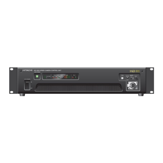
Page 18: Facility Names And Functions
Facility names and functions (Front) 1 CCU POWER switch CCU power on/off switch. 6 R TALLY LED 2 CCU POWER LED Lights at red tally input or when CALL signal is Lights when power is on. sent from camera. 3 CABLE CHECK LED 7 G TALLY LED Lights at green tally input. - Page 19 Facility names and functions (Rear) 13 HIGH SPEED OUTPUT connectors (BNC) 17 PROMPT connectors (BNC) Input analog video signal for the prompter. The Outputs 2 sets of three times high speed signal is sent to PROMPT out connector on signals as LINK A, LINK B and LINK C. CA-HF1500.
- Page 20 Facility names and functions (Rear & Front) 26 COMMUNICATION connector 31 Receiver Level LED (Front) The strength of the arriving light signal via fiber Intercom and tally signals are input from cable is indicated by position of lighting LED. external system. 27 WFM CONTROL connector This connector is used to select the display mode of the waveform monitor.
-
Page 21: System Configuration
CU-HD1500. 1. AC power supply operation When the CU-HD1500 CCU POWER switch is set to ON, the optical fiber cable connection is checked automatically (it takes about 5 seconds), and then power can be supplied to the camera by pressing the CAMERA POWER button to enable a video output signal. - Page 22 By carrying out the external input of the camera side power supply, long-distance cable transmission becomes possible. Directions for operation are as follows. 1) Between CU-HD1500 (camera control unit) is connected with CA-HF1500 (camera adaptor) by a single mode fiber cable. 2) The power supply of CU-HD1500 is switched on.
- Page 23 Viewfinder adaptor Viewfinder adaptor AT-90 AT-500 2-inch Viewfinder VF-402 Camera head SK-HD1500 Camera adaptor CA-HF1500 Camera control unit CU-HD1500 Fiber cable Portable Zoom Lens 9-inch Viewfinder Large Box Lens VF-L9HD / VF-L90HD Tripod adaptor Lens Mounter Setup control unit LM-B1000...
-
Page 24: Function Menu
Connect the camera control panel (RU-1500) or the setup control unit (SU-1000) to the CU-HD1500 to display the function menus on PIX video output. The function menus include the CCU menu to adjust the CU-HD1500 and the camera menu to adjust a camera. - Page 25 Function menu To display CCU menu, turn on color bars and then press FUNC button of the camera control panel. ■CU-FUNCTION ■OUTPUT SELECT ■RETURN SELECT ■MIC GAIN BUZZER :ENABLE HIGH SPEED : 1080i RET.CH SELECT MIC1 :-60dB SDI AUDIO :OFF HD1[1/2] : 1080i :RET.A1...
- Page 26 Function menu CU-FUNCTION menu ■CU-FUNCTION Item Setting Factory setting Description BUZZER ENABLE, ENABLE Sets buzzer operation during call input. BUZZER :ENABLE SDI AUDIO :OFF DISABLE ENABLE : Buzzer sounds. CCU ID *CABLE MODE: HYBRID DISABLE : Buzzer does not sound. SYS FORMAT 1080i 59.94Hz...
- Page 27 Function menu OUTPUT SELECT menu Item Setting Factory setting Description ■OUTPUT SELECT HIGH SPEED 1080i,720p 1080i Assigns output signal of HIGH SPEED OUTPUT connector HIGH SPEED : 1080i HD1[1/2] : 1080i HD/SD1[1/2] : 1080i HD1[1/2] 1080i,720p, 1080i Assigns output signal of HD1[1/2] connector. HD/SD2[1/2]...
- Page 28 Function menu MIC GAIN menu Item Setting Factory setting Description ■MIC GAIN MIC1 GAIN -10dB, -20dB, -30dB, -60dB Sets the sensitivity of the MIC1 line. MIC1 :-60dB -40dB,-50dB,-60dB, MIC2 :-60dB -70dB MIC2 GAIN -10dB, -20dB, -30dB, -60dB Sets the sensitivity of the MIC2 line. -40dB,-50dB,-60dB, -70dB MIC GAIN of camera can be controlled remotely when camera.is conncected.
- Page 29 Function menu SD DTL menu Item Setting Factory setting Description ■SD DTL SD DTL OFF,ON Enable the detail effect specialized for SD DTL :ON SDTV. H GAIN : 0 V GAIN : 0 H GAIN -128 to +127 Adjusts the horizontal detail level. H...
- Page 30 Function menu ECC filter indication When the FILTER setting is ON, the ECC filter is displayed at the lower center of the screen. The display depends on the optical filter position. ECC_FILTER A.3200K Displays ECC filter information B.4300K with optical filter 1. C.5600K D.6300K E.8000K...
-
Page 31: Cable Check , Warning Indication
Cable check, Warning indication Cable check CU-HD1500 automatically checks the condition of optical cable, and shows the results on both PIX OUT screen and LED indicators on front panel at start-up. If any troubles are detected, the camera power might be forced to shut down for safety. -
Page 32: Backup Battery Replacement
Backup battery replacement Backup battery replacement The backup battery is already mounted at the factory. If the time/date can not maintain accurate information, the alarm message “BACKUP BATT EMPTY” is shown on PIX OUT for about 6 seconds at start-up. In this case, the battery should be replaced, and the date and time should be adjusted at the TIME/DATE menu. -
Page 33: Service Information
Service information Connector pin diagrams INTERCOM (5 pin XLR female:HA16PRH-5S) MIC OUT 1,2 (3 pin XLR female:HA16RM-3SE) Combined connector:5pin XLR male Combined connector:5pin XLR male PUSH PUSH Signal Signal TALK (C) MIC GND TALK (H) MIC(H) IN RECEIVE (C) MIC(C) IN RECEIVE L (H) RECEIVE R(H) Remote 1,2 (4 pin female:HR10A-7R-4S(73)) - Page 34 Service information COMMUNICATION (25pin D-sub male:RDBD-25P-LNA(4-40)(55)) Combined connector: 25pin D-sub female Plug CCU mainframe Signal SYS2 SYS1 SYS0 PD OUT (C) 2W : OUT/IN(C) PD OUT (H) 2W : OUT/IN(H) PD SHIELD PD IN (C) 2W : NC PD IN (H) 2W : NC ENG OUT (C) 2W : OUT/IN(C)
- Page 35 Service information MIC REMOTE (15pin D-sub female: RDAD-15S-LNA(4-40)(55)) Combined connector: 15pin D-sub male Plug CCU mainframe SW ON :Lo Signal +5V OUT (200mA max) SW OFF:Hi TALLY GND 100kΩ G TALLY OUT R TALLY OUT MIC1 GAIN CTL2 MIC1 GAIN CTL1 MIC1 GAIN CTL0 MIC SEL1 MIC2 GAIN CTL2...
- Page 36 Service information TRUNK(9pin D-sub male:RDED-9P-LNA(4-40)(55)) Combined connector: 9pin D-sub female Plug CCU mainframe Signal → RX_RS-422+ or (RS-232C) (IN) ← TX_RS-422+ or (RS-232C)(OUT) → RX_RS422-(RTS (RS-232C)) *RS-232C(OPTION) ← TX_RS422-(CTS (RS-232C)) *RTS:Request To Send *CTS:Clear To Send WFM CONTROL (15pin female:YKF42-8043N) Combined connector: 15pin D-sub male Plug CCU mainframe...
- Page 37 Service information Switch setting for AC power supply J (Japan) :AC 100V 50/60Hz U (U.S.A.) :AC 117V 60Hz E (Europe ):AC 230V 50Hz Procedure 1. Loose two screws and lift the front panel slightly, and then pull it open. 2. Set two switches to supplied AC power voltage according to the diagram. Screw Screw Front panel...
- Page 38 Service information Intercom system setting CUH1200-MAIN SW3 –No.6 Clear SW18,19 SW20,21 2wire 4wire 2wire 4wire...
- Page 39 Service information Video frame rate setting The CU-HD1500 is switchable for video frame rate between 59.94 Hz and 50 Hz. The setting method is offered by the dip switch SW3–No.1 on CUH1200-MAIN board. When the dip switch SW6–No.1 is turned ON, the video frame rate can be switched by the dip switch SW3–No.2.
- Page 40 Insert the downloaded software that file name “Di32DL_4.2.0.3_Web.exe” The PC does not have to be connected to the CU-HD1500 at this time. c. Double click to install and follow the instructions on the screen to install the program on the PC.
- Page 41 If the CCU has set IP address, the PC has to be set “Use the following IP address” then input the IP address, Subnet mask, and Default gateway. 2.) Connect the CU-HD1500 to the PC as shown in the above figure. Execute the Lantronix DeviceInstaller application by START > ALL PROGRAMS > LANTRONIX > DeviceInstaller 4.2 >...
- Page 42 Service information If the IP Address of the CU-HD1500 is highlighted, and the "Home" button on the screen is clicked, the Network Settings are displayed on the right pane of the DeviceInstaller program. Note that only the IP Address can be changed on the Network Settings pane. When it is necessary to change the port number of the CCU, click on the “Serial Settings”...
- Page 43 Service information When CU-HD1500 is changed to arbitrary [IP Address], [Subnet Mask], and [Default Gateway], and the address is retrieved, it is necessary to match IP Address of PC, Subnet Mask, and Default Gateway. (Enough operational administrative to IP Address etc.)...
-
Page 44: External View
External View CU-HD1500 External View (Unit: mm) -
Page 45: Specifications
10kg approx. Maximum cable distance 1km (Full operation) 4km (Without utility power) ■Input output signals (CU-HD1500) Input signals Camera Control Unit CU-HD1500 (INPUT) GEN LOCK IN B-BST 0.45Vp-p/75Ω(loop through) BNC x1 or HDTV tri-level sync 0.60Vp-p/75Ω (loop through) DIGITAL RET IN(A) 1/2/3/4... - Page 46 Specifications Output signals Camera Control Unit CU-HD1500 (OUTPUT) HIGH SPEED OUTPUT HD-SDI BNC x6(x2+x2+x2) LINK A, LINK B, LINK C (1/2) (Embedded 2-Chnl audio available) ・1080i : SMPTE292M ・720p : SMPTE292M DIGITAL OUT HD-SDI BNC x2 HD1 (1/2) (Embedded 2-Chnl audio available) ・1080i : SMPTE292M...
- Page 47 Specifications ■Accessories ・Remote control unit ・Setup control unit ■Standard Composition ・Camera Control Unit : CU-HD1500 ・Code Set(U/J) : WC0051(0234-0089A 2.5M) (8488057) ・Code Set(E) : VM0306B;VM0303B 2.5M (BBZ0399) ・Operation Manual : CU-HD1500 O/M : HDBB-25S(05) (8AAE000522) ・Connector ・Plug Case : HDB-CTH(4-40)(10) (JYHS003) : HDEB-9S(05) (2PBB018260) ・Connector...