
Related Manuals for ABB Sentry BSR23


Summary of Contents for ABB Sentry BSR23
- Page 1 SAFETY PRODUCTS Safety relays Sentry BSR23 Product Manual 2TLC010062M0201 Rev.F ORIGINAL INSTRUCTIONS...
- Page 2 NEVER USE THE PRODUCTS FOR AN APPLICATION INVOLVING SERIOUS RISK TO LIFE OR PROPERTY WITHOUT ENSURING THAT THE SYSTEM AS A WHOLE HAS BEEN DESIGNED TO ADDRESS THE RISKS, AND THAT THE ABB PRODUCT IS PROPERLY RATED AND INSTALLED FOR THE INTENDED USE WITHIN THE OVERALL EQUIPMENT OR SYSTEM.
-
Page 3: Table Of Contents
Table of Contents 1 Introduction................................Purpose of document ............................Intended audience..............................Reading prerequisites ............................Special notes ................................. 2 Safety ..................................Intended use ................................Safety precautions ............................... 3 Product description............................... Sentry safety relays .............................. Sentry product range............................Safety relay overview ............................4 Installation ................................ - Page 4 LED operation indication and error status...................... 18 10 Model overview ..............................20 10.1 Sentry models................................ 20 10.2 Accessories and spare parts ..........................21 11 Dimensions ................................22 11.1 Sentry ..................................22 12 Technical data ................................ 23 12.1 Technical data ............................... 23 13 Declaration of conformity ............................
-
Page 5: Introduction
Intended audience This document is intended for authorized personnel. Reading prerequisites It is assumed that the reader of this document has: • Basic knowledge of ABB safety products. • Knowledge of machine safety. • Knowledge of safety devices. Special notes... -
Page 6: Safety
Safety Intended use The intended use of the Sentry safety relay is to monitor the state of a safety device and depending on the state, activate or inactivate the outputs within the system response time. The protective function of the safety device is only safe if the safety relay is correctly connected and configured. -
Page 7: Product Description
Product description Sentry safety relays Sentry safety relays provide safe stop and start of monitored devices to prevent errors. The following safety device types are applicable for the Sentry safety relays: • 1 channel safety device. • 2 channel safety device with equivalent contacts. •... -
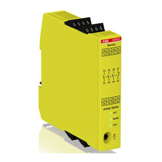
Page 8: Safety Relay Overview
Safety relay overview Connection block, top side back. Connection block, top side front. Product name. Print for connection block, top side back. Print for connection block, bottom side front. Relay output configuration. Print for connection block, top side front. Print for connection block, bottom side back. LEDs for status indication. -
Page 9: Installation
Installation Installing precautions Follow the instructions carefully to avoid personal injury or damage to the device. The safety relay shall be attached on a 35 mm DIN rail in a lockable enclosure that has at least protection class IP54. Sentry safety relays shall be installed in an upright position. Make sure there is at least 10 mm distance between the safety relay and other non-Sentry units to prevent uncontrolled heating. -
Page 10: Removing The Safety Relay From The Din Rail
Removing the safety relay from the DIN rail Use a screwdriver to unlock the DIN relay latching device from the DIN rail. 2. Pull the bottom rear side of the safety relay away from the DIN rail until a click is heard. 3. -
Page 11: Connecting Precautions
Connecting precautions Disconnect the power supply before attaching or removing the Warning! connection blocks. Make sure that connection blocks and wires are clearly marked for correct connections. Use applicable requirements in IEC 60204‑1 for wire connections. Make sure that the wires are fitted with crimp terminals or ferrules before connection, unless solid copper conductors are used. -
Page 12: Connecting To A Screw Compression Type Terminal
Connecting to a screw compression type terminal Use a screwdriver with slot size 3,5 mm. Open the terminal before inserting a wire. 2. Insert the wire in the correct terminal. 3. Close the terminal and secure the wire with torque 0,7 Nm ±0,1. Connecting to a push-in type terminal Press the actuating lever. -
Page 13: Functions
Functions Function overview Power supply, 24 VDC via safety device Relay output • 4 NO + 1 NC • One channel • Two channels with equivalent contacts (no 2 channel monitoring) • Expansion of PLC outputs Test, start and reset interface •... -
Page 14: Test, Start And Reset Interface
Arc suppression for inductive loads is recommended to get a longer Note! lifetime for the relay contacts. Test, start and reset interface The safety relay has an interface for test, start and reset functions. The safety relay enters inactive mode when at least one input is not accepted. The safety relay enters active mode when the inputs are accepted, and a reset is performed. -
Page 15: Connections
Connections Connection groups The connections are divided into groups. Power supply Signal from safety device Test/reset/start/indication 13, 23, 33, 43 Safety output, NO 14, 24, 34, 44 Safety output, NO Output, NC Output, NC 2TLC010062M0201 Rev.F... -
Page 16: Application Connections
Application connections Connection examples SENTRY BSR23 SENTRY BSR23 Always use transient suppressors when inductive loads are connected Note! to the relay outputs. 2TLC010062M0201 Rev.F... -
Page 17: Maintenance
In case of breakdown or damage to the safety relay, contact nearest ABB Electrification service office or reseller. ABB will not accept responsibility for failure of the functions if the installation and maintenance requirements shown in this document are not implemented. These requirements form part of the product warranty. -
Page 18: Troubleshooting
Troubleshooting Front LEDs The three LEDs in the safety relay front indicates operation status and errors in the system. A. CH1 24 V on A1/R1 B. OUT Output status C. CH2 24 V on R2/A2 LED operation indication and error status Status Action No channel is... - Page 19 Status Action green green Channel 2 is stuck Exchange the safety relay 2TLC010062M0201 Rev.F...
-
Page 20: Model Overview
Model overview 10.1 Sentry models The connection blocks are delivered without coding. The coding kit is an optional accessory and is ordered separately. Model Order code Description BSR10 2TLA010040R0000 Screw compression connection blocks. 24VDC Push-in connection blocks. BSR10P 2TLA010040R0001 24VDC BSR11 2TLA010040R0200 Screw compression... -
Page 21: Accessories And Spare Parts
Model Order code Description TSR20 2TLA010061R0000 Screw compression connection blocks. 24VDC Push-in connection blocks. TSR20P 2TLA010061R0001 24VDC TSR20M 2TLA010061R0100 Screw compression connection blocks. 85-265VAC/120-375VDC Push-in connection blocks. TSR20MP 2TLA010061R0101 85-265VAC/120-375VDC USR10 2TLA010070R0000 Screw compression connection blocks. 24VDC Push-in connection blocks. USR10P 2TLA010070R0001 24VDC... -
Page 22: Dimensions
Dimensions All dimensions are in mm. 11.1 Sentry Measure Connection block type Screw connection type Push-in type 22,5 22.5 2TLC010062M0201 Rev.F... -
Page 23: Technical Data
It may represent the result of ABB’s test conditions, and the users must correlate it to actual application requirements. Actual performance is subject to the ABB Warranty and Limitations of Liability. - Page 24 BSR23 is supplied with power through its signal input port R. Note! Relay output specification Relay output configuration 4 NO + 1 NC Note Maximum operating switching voltage 250 VAC Overvoltage category Rated impulse withstand voltage 4 kV Rated operational voltage 250 VAC Minimum operating contact load 5 VDC / 10 mA (15 VDC / 3 mA)
- Page 25 Test/start/reset interface specification Applied voltage rating Minimum 5 VDC Maximum 300 VDC Response time Delay at power on ≤ 40 ms Response time at inactivation ≤ 20 ms Electrical operations lifetime Load Σ lth ≤ 64 AC1, AC15 160 000 operations DC1, DC13 100 000 operations Measurement conditions:...
- Page 26 Environmental data Altitude Suitable for use at ≤ 2000 meters above sea level Vibration 10-55 Hz sine, 0.35 mm (1 oct/ min 20 sweep cycles, all directions) Shock 5g, 11 ms Half sine +/- 100 Shocks EU Directive Compliance Directives European Machinery Directive 2006/42/EC EMC Directive 2014/30/EU RoHS Directive 2011/65/EU...
- Page 27 Approvals UKCA Standard IEC 61508 4.1E-9 and PFD 6.8E-6 EN ISO 13849-1, EN 62061 4.1E-9 Mission time 20 years Information for use in USA/Canada Intended use Applications according to NFPA 79 Power source A suitable isolating source in conjunction with a fuse in accordance with UL248.
-
Page 28: Declaration Of Conformity
Declaration of conformity 2TLC010062M0201 Rev.F... - Page 29 EC Declaration of conformity (according to 2006/42/EC, Annex 2A) ABB AB declare that the safety components of ABB AB manufacture with JOKAB Safety type designations and safety functions as listed below, is in Varlabergsvägen 11 conformity with the Directives SE-434 39 Kungsbacka...
- Page 30 Declaration of conformity (according to 2008 No 1597) ABB Electrification declare that the safety components of ABB AB manufacture with type Sweden AB designations and safety functions as listed below, is in conformity SE-721 61 Västerås with UK Statutory Instruments (and their amendments) Sweden 2008 No 1597 –...
- Page 31 2TLC010062M0201 Rev.F...
- Page 32 ABB Electrification Sweden AB SE-721 61 Västerås Sweden...